INTRODUCTION
The exposed cables and connectors used in PV source circuits are some of the most critical components of a PV system in terms of maintaining system durability and safety. These components are exposed to the extremes of weather for the life of the system and may be required to be durable and safe longer than the system will actually produce power. PV modules have a warranted life span for power output of 25 years, but they may produce dangerous amounts of voltage and current for as long as 40 or 50 years. And, in many cases there will be a functioning or more likely nonfunctioning inverter attached to that PV array output for that length of time. The quality of the components used and the care taken in complying with the code determine the durability and ultimate safety of these cables and connectors.
CONNECTORS
Recognized Components
PV modules come with connectors attached to the ends of the cables that have been permanently attached to the PV module. See photo 1. There are multiple connector manufacturers supplying connectors to the module manufacturers, and modules with a wide variety of connectors are being used. These connectors can only be recognized components (RC) because they cannot meet the more stringent requirements of a listed connector which would require that the connector be capable of being opened under load or opened at full current and full rated voltage. An example of a listed, load break rated connector would be the AC plug used on appliances and the 120-V ac receptacle in our houses. The PV connectors, if they were to be listed, would have to be able to safely open a circuit at 600 V or even 1000 V dc at the rated current of the module, which could be in some cases as high as 10 or 12 A. Interrupting direct currents (dc) is considerably more difficult than interrupting alternating currents (ac) and at this time, none of these PV connectors are rated for load break operation at full voltage.
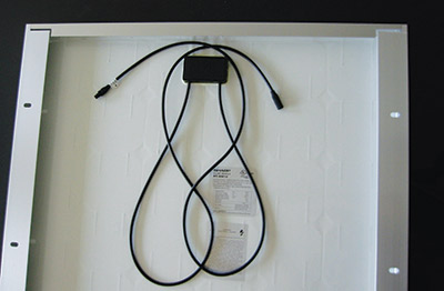
Photo 1. PV module with attached cables and connectors.
The exception to this Recognized Component rating relates to the connectors on some microinverters that have been listed with the inverter as a disconnecting means when used at the lower voltages and less strenuous operating conditions of these devices. These connectors meet the requirements of 690.15(A)/2014, 690.14(D)/2011. See photo 2.
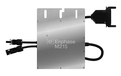
Photo 2. Mircoinverter with ac and dc connectors listed with the microinverter as disconnecting means.Courtesy Enphase Energy
Compatibility Issues
Some connector manufacturers are advertising that some of their connectors are interchangeable with the connectors of other manufacturers in terms of an electrical and mechanical compatibility. And, upon casual inspection by the AHJ and the PV installer, this mechanical and electrical compatibility appears to be true. Unfortunately, Underwriters Laboratories and the members of the Standards Technical Panel for UL Standard 6703 for connectors are discussing the fact that none of these mixed pairs of connectors have been evaluated for compatibility by an independent third party Nationally Recognized Testing Laboratory like UL, CSA, TUV and ETL—the four OSHA-recognized NRTLs authorized to certify PV equipment. Each connector manufacturer modifies the materials and procedures used to manufacture their connectors in a proprietary manner. Even though there may be an electrical and mechanical compatibility at one point in time, there is no continued evaluation to ensure that changes in the production process of one manufacturer will result in their connectors remaining compatible with the connectors from another manufacturer.
It is fairly easy to understand how a slight modification of the metals used in one connector while being compatible with the metals in the mating connector by the same manufacturer, would not be compatible over long periods of time with the metals used in a connector by another manufacturer. In a similar manner, a modification of the plastics used in one connector, while meeting the requirements to perform effectively with the plastics from the same manufacturer in the mating connector, may not be compatible over the long term with the plastics used by another manufacturer. Even minute differences in the thermal expansion rating of different plastics could pose problems.
These connector assemblies must remain electrically and mechanically secure for the very long power production life of the PV module. They must be watertight and not allow water to reach the electrical connection. They must be mechanically strong and not separate under the high wind loadings, ice loadings, and possibly thermal stress to which they may be subjected. There can be no deterioration of the electrical contact due to a mismatch, however slight, of the metals used in each half of the mating connectors. When viewing the connector as a splice in the cable, the code requires that the splice be at least as robust as the un-spliced cable before the connector was inserted at that point [110.14(B)].
When connectors are mixed and matched, the listing and certification of the PV module as a complete assembly including the connectors comes into question. If a mixed pair of connectors should fail either electrically or mechanically and cause damage at some time in the future, the listing of the module, and compliance with NEC requirements including sections 690.4(D) and section 110.3(B) could be a significant issue.
At this time, connectors should only be mated in pairs from the same manufacturer. If equipment must be connected that uses connectors from different manufacturers, then some sort of cable connector adapter must be field manufactured or purchased that will allow the connectors to be mated in pairs from the same manufacturer. It is probably not a good idea to cut connectors off of a given product and change those connectors to a connector set from a manufacturer that will mate with the connector set on the other product. Although engineers at Underwriters Laboratories have said this procedure does not violate the listing on the product, several PV module manufacturers have stated that cutting the connectors off of their listed product will invalidate the warranty on that product. Therefore, it might be more appropriate to make a short length of cable with different connectors on each end to keep the mating pairs from the same manufacturer together even though this will double the number of connectors in the circuit.
Factory Training and Factory Tools Required
When it comes to installing connectors on cables in the field, caution is advised. In general, Recognized Components may not be installed by themselves in the field, but are supposed to be installed only in the factory under factory-controlled conditions. This is a gray area in the UL Standards and in the Code. It is generally acknowledged, but not in writing anywhere, that a Recognized Component PV connector must be installed by a person having manufacturer’s training on the installation of the connector and using manufacturer’s approved tools to assemble the connector to the cable (photo 3). And since there are a significant number of different cables being used, the compatibility of connector with a particular cable must be determined.
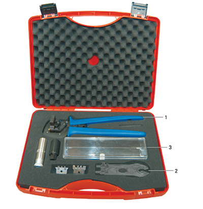
Photo 3. Connector assembly tools. Courtesy MultiContact
CABLES
Construction
Nearly all PV module manufacturers are using “PV cable/PV wire” fastened to their modules. See 690.35 and 690.31. PV cable or PV wire is that cable meeting UL Standard 4703 for the use on modules and in exposed PV source circuits on ungrounded PV arrays which, in turn, can be connected to the transformerless (non-isolated) PV inverters. These inverters are becoming more common in PV installations in the United States (690.35). And, of course the old standby USE-2 conductors can be used for exposed, source circuit wiring on grounded PV arrays. See “Perspectives on PV” in the March-April 2014 issue of the IAEI News for more details on grounded versus ungrounded PV systems.
UL Standard 4703 allows a wide variety of materials and construction configurations to be used for the manufacture of PV cables so that they may be used both in the United States and in Europe. In Europe, the requirement for PV cables generally means that the cables must be fine-stranded, flexible cables and have tinned conductors. PV systems integrators and PV installers should exercise caution when purchasing bulk spools of PV cable/wire in the US that may have the fine stranding. It is difficult to find terminals on equipment such as dc combiners and inverters that can accept fine stranded cables here in the US. Note the warnings on this problem in 110.14(A), 690.31(F), and 690.74(A).
Although all PV cable/wire is marked sunlight resistant and has been tested for UV resistance with 720 hours of acceleration UV testing, some care must be exercised in selecting conductors that will withstand decades of use and exposure in PV environments. It is generally acknowledged that conductors with black insulation will last significantly longer than cables with colored installation and this applies both to PV cable/wire and USE-2. Also, conductors with synthetic rubber insulation (thermoset) may last longer than conductors with PVC insulation (thermoplastic), although both can be used in the construction of PV cable/wire.
Ampacity – More than memorizing a few numbers from a Code Table
It should be noted that the ampacity requirements in Sections 210.19 (A) (branch circuits) and 215.2(A)(1) (feeders) of the 2014 NEC are now worded in a similar manner to the PV ampacity calculations in 690.8. The feeder and branch circuit ampacity calculations are based on continuous and non-continuous loads. The PV ampacity calculations are based on maximum currents, which are similar to continuous loads with the knowledge that there are no non-continuous currents in PV systems and all maximum currents are based on worst-case continuous currents.
The conductors attached to the PV module have been sized by the manufacturer based on the rated short-circuit current of the module and the anticipated worst-case conditions of use which, for these exposed single conductors, would be the environmental temperature.
However, when these conductors are attached to the source circuit conductors running to the DC combiner or the inverter, the source circuit conductors may be in a different environment. This environment could include single conductors in free air or multiple conductors in conduit, and the conduits could be subjected to additional heating from sunlight. The installer and the inspector should be aware that the source circuit conductors due to these additional “conditions of use” adjustment factors may have to be a larger gauge than the conductors attached directly to the PV module.
Several factors should be considered when evaluating the ampacity requirements for these conductors. The ampacity values in table 310.15(B)(17) are to be applied only to single conductors in free air. If the exposed single conductors are grouped or fastened together in bundles of two or more, this table no longer applies and table 310.15(B)(16) should be used for ampacity calculations. The Code is somewhat gray when 12 source circuit conductors are bundled together in free air or possibly in a cable tray. Should a “conduit fill” adjustmemt factor be applied?
Considering all of the conditions of use adjustment factors in section 310.15, it would appear that the worst-case adjustment factors would be found when the greatest number of conductors are in a conduit and that conduit is in the sunlight and is closer to the roof than other conduits. As the number of conductors in a conduit decreases, the conduit is not in sunlight, and if in sunlight, is further from the roof than other conduits in sunlight, the adjustment factor becomes less severe.
After identifying, this worst-case environment for adjustment factors, and before making the ampacity calculations, The Exception to Section 310.15 (A) (2) should be examined. In most cases, the PV source circuits from the modules to the dc combiner or the inverter will be subjected to several different conditions of use in a single circuit. The 10-foot or 10% allowance should be applied and may result in a smaller conductor size. This allowance is made because copper and aluminum conductors are fairly good thermal conductors and can transfer and dissipate heat from a short length of conductor in a high temperature environment to an adjacent conductor in a lower temperature environment under certain conditions. The Exception to 310.15(A)(2) allows the ampacity associated with the less stringent conditions of use to be applied.
Mechanical Attachment
Even the highest quality cables and properly mated connectors will not survive decades of outdoor abuse unless they are properly secured to the module and racking structure. Unfortunately, nylon cable ties, even the black ones marked UV resistant are not withstanding the test of time in the PV environment. Again, these cable ties generally have not been tested with more than 720 hours of accelerated UV tests, which is equivalent to about 2 1/2 years of outdoor exposure. In actual PV applications, particularly in the hotter Southwest regions of the country, some of these are failing in just a few years. Several manufacturers have brought to the market stainless-steel metal cable clips that are suitable for this application and will withstand the test of time. These clips or something similar like the rubber insulated stainless-steel clamp shown in photo 4 should be used.
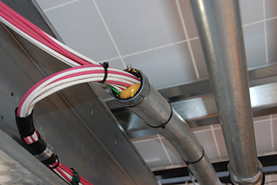
In a related area, the entry of all of these exposed conductors into conduits or DC combiners should be made with an appropriate conduit or opening termination fitting. Open conduits or conduits closed with non-electrical foam products should not be used. See photos 5, 6, and 7.
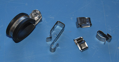
Photo 4. Durable stainless-steel cable clamps and fasteners. Clips courtesy Nine fasteners.
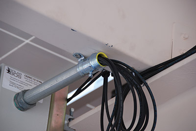
Photo 5. Open conduit entry to DC combiner should not be used.

Photo 6. Many potential issues: EMT clamp and tape used to secure bundle of cables, plastic wire ties, foam sealant, and colored (non black) PV wire insulation.
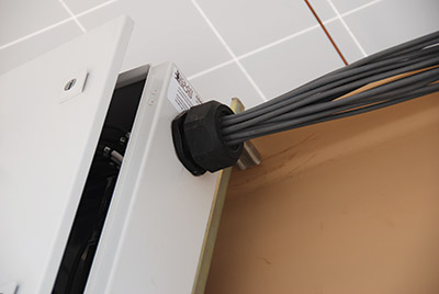
Photo 7. Proper termination fitting for exposed conductors entering a dc combiner.
Summary
Inspectors and plan reviewers as well as PV systems integrators and PV installers should be aware of the specific requirements for the specialized conductors and connectors used in the exposed PV source circuits in the PV array. The ampacity of these conductors may vary significantly depending on the environment to which they are subjected. To ensure durability, and more importantly safety, for the 40- to 50-year electrical life of the PV module, these connectors and conductors must be installed correctly and with careful attention to all Code requirements and to even a few factors not now contained in the Code.
The author has retired from the Southwest Technology Development Institute at New Mexico State University, but is devoting about 25% of his time to PV activities in order to keep involved in writing these Perspectives on PV articles in the IAEI News and to stay active in the NEC and UL Standards development. He can be reached, sometimes, at: e-mail: jwiles@nmsu.edu, Phone: 575-646-6105
The Southwest Technology Development Institute web site maintains a PV Systems Inspector/Installer Checklist and all copies of the previous “Perspectives on PV” articles for easy downloading. A color copy of the latest version (1.93) of the 150-page, Photovoltaic Power Systems and the 2005 National Electrical Code: Suggested Practices, written by the author, may be downloaded from this web site: http://www.nmsu.edu/•tdi/Photovoltaics/Codes-Stds/Codes-Stds.html