Introduction
Let’s assume that the direct current (DC) source circuits have been combined in a DC combiner or are being run individually to a combiner internal to the inverter. Assuming that any alternating current (AC) circuits from microinverters or AC PV modules have been combined in an AC combiner. The detailed National Electrical Code (NEC) requirements of running these combined or individual circuits to the utilization equipment need to be examined. Also, there are a number of disconnects throughout the PV system and associated power systems that need to be properly marked and identified.
The Basics
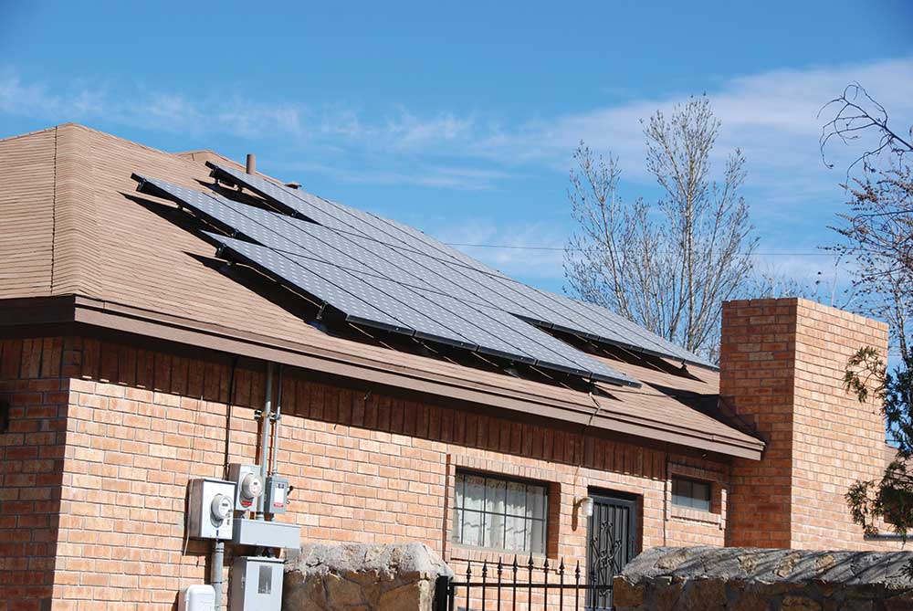
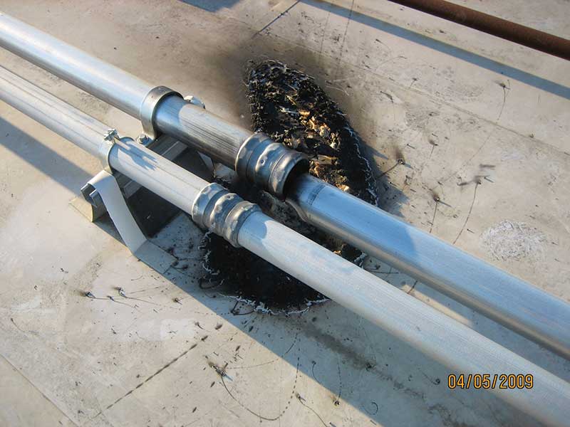
Several different wiring methods may be used to route the power from the PV array to the utilization equipment. Photo 1 is not one of them. Where raceways, typically EMT or other conduits are routed in the sunlight across the roofs and down the sides of buildings, consideration must be given to temperature-induced expansion and contraction. From cold winter nights to hot summer days with raceways exposed directly to sunlight, the expansion in the raceway between the cold temperatures and the hot temperatures can be significant. Almost every section of the NEC dealing with raceways requires that expansion due to temperature changes be addressed where the potential for expansion exceeds one-quarter of an inch (.25 in-6 mm).
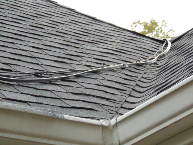
PVC conduit (not recommended for outdoor exposed PV systems due to potential longevity issues) and other plastic raceways will exceed this 0.25 expansion limit even with modest temperature changes and short lengths. See Table 352.44 for the information. While the expansion of metallic raceways like the commonly used EMT is significantly less (0.2 times the PVC expansion), the installation of these raceways may still need to consider thermal expansion when 10–20 feet or more of conduit is subjected to temperature ranges from a cold winter night at -10°C (14°F ) to a hot summer day with a raceway temperature at 60+°C (140+ °F). See photo 2.
These high conduit temperatures in sunlight will also affect the ampacity of the conductors in that conduit, and the conductor sizes based on the maximum currents will generally have to be adjusted. This, in turn, may require an increase in raceway size.
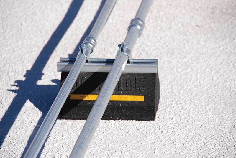
Ampacity Calculations. In most circuits, the conductor size calculation will start with the maximum current, which is 125% of the module short-circuit current or 125% of the parallel-connected module short-circuit currents at the output of the DC combiner [690.8(A)(1)]. The output of microinverters or AC PV modules (photo 3) will have the maximum current equal to the microinverter rated output current [690.8(A)(1)]. This maximum current is subjected to further modification by an additional multiplying factor of 125% or an adjustment for the conditions of use [690.8(B)]. When dealing with circuits and raceways exposed to sunlight, the conditions of use adjustment will be the one that usually will result in the largest conductor size requirement.

Disconnects, Plaques, and Directories. The output of the PV system — either dc from the modules, dc-to-dc converters, ac from microinverters, or AC PV modules — is one source of power/energy that will require one or more disconnects (photo 4). The requirements for dc disconnects and equipment isolation devices are found in Article 690, Part III, Sections 690.13 and 690.15. To fully understand the requirements for disconnects and understanding where the PV system ends and where other power sources begin, the diagrams in the Informational Notes of Figure 690.1 provide some visibility into this as do the definitions found in 690.2. Specific types of disconnects and the various requirements for them will be addressed more thoroughly in subsequent articles.

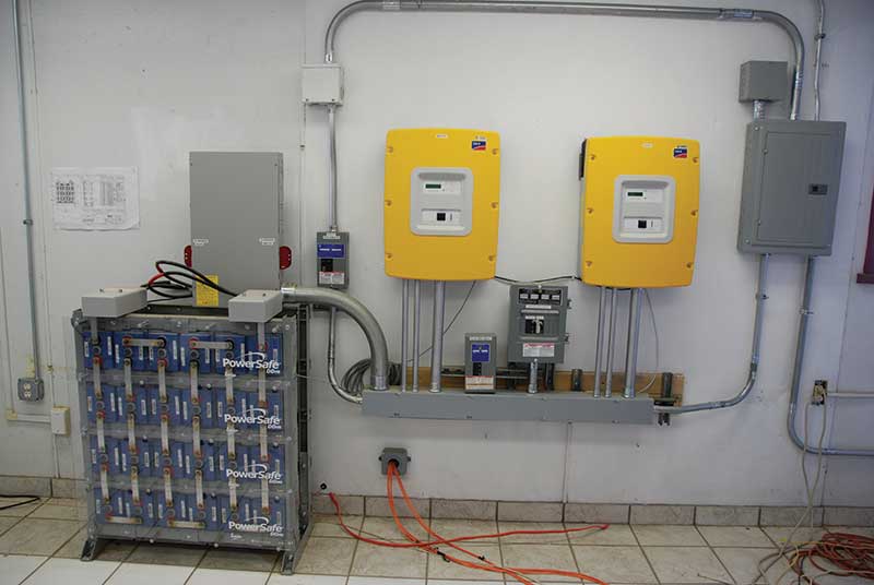
The utility service is, of course, another source of power in the electrical system, and the PV system may be interactively connected to that utility source. Also, with increasing frequency, energy storage systems (ESS) [aka battery systems] are being installed in residential, commercial and utility sized PV systems. ESS represent yet another source of energy for the facility and will require a source disconnect (photo 5). And there are numerous completely standalone PV systems that are not connected to any electrical utility power source. The most recent power source that may be found in buildings is the dc microgrid, which may operate in a standalone manner or be interconnected with other sources of power.
Sections 690.54 and 690.56 (PV Systems), 705.10 (Interconnected Power Systems), 706.21 (ESS), 710.10 (Stand-alone Systems), and 712.10 (DC Microgrids) all deal with the directory and placarding requirements for all of the various power sources. These requirements are critical because they allow easy and rapid identification of these various power sources and how they can be disconnected by Fire Service personnel and other first responders. This is a life safety function.
Each of these power sources, including the utility, any energy storage system, any standalone system, any dc microgrid system, and any combination of these power sources have specific Code-required plaques and directories. A summary of these requirements indicates that a permanent directory or plaque should be located at the disconnect for each source, showing the location of all other power source disconnects in the building or structure. A bold warning should be on each plaque or directory: “CAUTION: MULTIPLE SOURCES OF POWER,” and the markings should comply with 110.21(B) and 110.22(A). Any diagrams showing the locations of the other disconnects must be correctly oriented with respect to the diagram’s location (705.10). See photo 6.

Looking Deeper
Conduit Expansion. The actual conduit temperature in exposed (to sunlight) locations will vary greatly. In many places in the US, the nighttime, winter temperatures can be -10°C (14°F) or lower. On a hot summer day, the ambient temperatures could be 40°C (104°F), but the rooftop temperatures on flat roofs (low slope roofs) with parapets blocking wind flow (or no wind conditions) may experience a heat bubble of an additional 10 to 15°C on the roof plus the solar heating of the conduit. So, before the sun hits the conduit, the temperature of the conduit could be 50°C (122°F), and then the distance of the conduit from the roof will have to be determined.
Section 310.15(B)(2) requires that raceways or cables exposed to direct sunlight on roofs where the bottom of the raceway is less than seven-eights of an inch from the roof have a 33°C (60°F) temperature added to the outdoor ambient temperature in the conduit location. Using the temperatures above, the actual conduit could be as hot as 83°C (182°F). A more conservative approach, particularly in the hot sunny Southwest areas of the country, would be to use the temperature adders in Table 310.15(B)(3)(c) in the 2014 NEC, even for systems being installed under the 2017 and later editions of the Code. This approach is suggested due to the very long life of a PV system installation (40–50+ years) and the fact that annual average temperatures are increasing.
The change in temperature that a conduit in this location would be exposed to from winter to summer is -10°C to +83°C (14°F to 182°F) which gives a change in temperature of 93°C (168°F). If the conduit were PVC (again not recommended for PV outdoor installations), Table 352.44 would indicate an expansion of about 6.8 inches per 100 feet of conduit. For a 10-foot length of conduit, the expansion would be 0.68 inches, which certainly exceeds the 0.25-inch expansion limit for an installation without expansion fittings. If we look at steel EMT conduit, the Informational Note in Section 300.7(B) says that the PVC expansion distances can be multiplied by a factor of 0.20 to get the steel expansion. With a PVC expansion from the above temperatures of 0.68 inches, under a similar temperature range, a 10-foot section of steel EMT would expand 0.136 inches. A 20-foot section of steel EMT would expand 0.272 inches and, according to the Code limitation of 0.25 inches, require an expansion fitting.
The requirement for expansion fittings applies to straight sections of conduit or the raceway when each end is properly terminated by a fixed, nonmoving device such as a junction box. A related issue is that any type of raceway must be supported at varying distances depending on the type of raceway being used. These support devices must be firmly attached to the roof yet, at the same time, allow the conduit to move freely as it expands and contracts. This requirement to allow expansion generally indicates that special support devices will be required (photo 7). The roof attachment methods for the support devices should be fully waterproofed since they may penetrate the roofing membrane.
Another issue related to the use of conduits in exterior locations is that rainproof fittings/raintight fittings must be used to couple sections of EMT and also to connect EMT to various boxes and other equipment. The use of expansion joints keeps these fittings from being pulled loose from the EMT (photo 7).
Ampacity Calculations. The conductors in conduit exposed to sunlight are subjected to the same high temperatures as the conduit itself. The ampacity of those conductors must be corrected for those high temperatures. Here is an example.
One of the newer 400 W PV modules has a short-circuit current of 10.3 A. To determine the maximum current, the short-circuit current is multiplied by 1.25, yielding a 12.9 A maximum current (690.8). This current is now adjusted for the high temperature that we expect in the sunlight heated conduit on the hot roof where the ambient temperatures in the surrounding area are 40°C (104°F). The adjustment factor found in Table 310.15(B)(1) for an expected raceway temperature of 83°C is 0.29. Correcting the 12.9 A maximum current by this 0.29 factor yields a current of 44.5 A, which is used to select a conductor size. Table 310.16 shows that an 8 AWG conductor would be needed because the normally used 10 AWG conductor is limited to 40 A.
This is an area where caution should be exercised. Many installers seeing even a large module with a short circuit current of 10.3 A, would normally use a 10 AWG conductor for the source circuit. However, as shown above, that 10 AWG conductor would be too small after the various heating considerations are considered and, with PV systems lasting 40 to 50 years with little maintenance, conductor longevity is extremely important.
The Saving Grace Section. The Exception in 310.15(A)(2) allows the higher ampacity of a circuit to be used for the entire run where the hotter section does not exceed 3.0m (10 feet) or 10 percent of the total circuit. In the case of multiple different temperature segments on a single circuit, it appears that the design must start with the highest temperature segment and apply this exception to it and the adjacent lower temperature segments on either side for the total length. In this case, it being the sum of the lengths of the hot segment and the lengths of the two adjacent cooler segments. The concept is that the cooler segments may be able to reduce the temperature of the hotter segment if it is short enough.
It should be noted that recent editions of the NEC have exempted XHHW-2 insulated conductors from the sunlight heating of conduit factor. Still, it should be kept in mind that this conductor is listed as a 90°C conductor and the listing restrictions may not be violated [110.3(B) and 310.14(A)(3)] and will override other NEC allowances.
Another situation might occur when rooftop temperatures and sunlight exposure preclude the installation of a dc or ac combiner on the roof. In these cases, the output of multiple strings (source circuits) of PV modules or the outputs of several ac trunk cables from microinverters or AC PV modules may be installed in the same raceway, which is then routed to an indoor location where the combiners are mounted. In addition to the temperature adjustments shown above, an additional factor for conduit fill will be required, and this factor is given in Table 310.15(B)(3)(a). Each of these circuits will have a least two current-carrying conductors, and with two to three circuits, 4-6 conductors will be in the raceway. This situation will require an additional derating factor of 80%. This may require a larger conductor to handle the current after both the temperature and conduit fill conditions of use have been applied. And, in some cases, after the conductor size is increased to meet ampacity requirements, the conduit size will have to be increased.
For example, 12 strings (source circuits) are being routed directly from the PV array through a large EMT mounted ½ inch from the roof (on short support devices) to the dc combiner built into the 60 kW inverter which is located inside the building. Assuming that the same 400 W module is used with a 10.3 amp short-circuit current, that will be the short-circuit current for each string, and each string will have two current-carrying conductors in the EMT. With 24 current-carrying conductors in the conduit, the ampacity calculations for this high-temperature environment would be as follows:
10.3 (Isc) x 1.25 = 12.9 amperes maximum current
Isc x 1.25 = 12.9 amps maximum current.
12.9 amps adjusted for the 83°C EMT temperature by a factor of 0.29: 12.9/0.29 = 44.5 amps
Table 310.15(C)(1) indicates that a 45% factor will be required to address the 24 current-carrying conductors. 44.5/0.45 = 98.9 A and Table 310.16 shows that 3 AWG conductors would be required.
Continuing the example to include the EMT size, there will be 25 conductors in the EMT when a single equipment grounding conductor is included. Table C.1 in Annex C indicates that a 3.5-inch EMT would be required if RHW-2 conductors were used. If XHHW-2 conductors were selected (recommended for durability), Table C.1 shows that only a 3-inch EMT would be required.
Working all of the Code Allowances. If the Exception on 310.15(B)(2) is used for the XHHW-2 or the EMT is raised more than 7/8 inch above the roof, then the conduit temperature could be reduced by 33°C to 50°C, and the ampacity equations would be revised as follows:
First, the maximum current is again calculated.
10.3 x 1.25 = 12.9
Temperature adjustment factor for 50°C is 0.82
12.9/0.82 = 15.7 amps
Conduit fill factor remains at 45%
15.7/0.45 = 34.9 amps
And the conductor size requirement is now 10 AWG of XHHW-2 conductor.
Table C.1 shows that a 1.5-inch EMT would be required, a considerable savings. As mentioned previously, the conservative PV designer may want to revert to the conduit in sunlight temperature adders in the 2014 NEC, which could result in a larger conductor size and raceway size
Another available option is to route the conductors from each of the twelve source circuits in individual ½-inch EMT from the array to the inverter. An equipment-grounding conductor would have to be included in each raceway, and the calculations repeated coupled with cost data to make the full comparison.
Disconnects, Plaques, and Directories. The requirements associated with power source disconnects, plaques, and directories should be merged with the requirements for the PV Rapid Shutdown System initiator requirements (690.12) and the requirement for emergency utility disconnects for one- and two-family dwellings (230.85). The emergency disconnect for the utility service conductors may be one of three different devices and must be located in a readily accessible outdoor location.
This outdoor location, presumably on the outside of the building or structure near where the service entrance conductors enter the building (not a code requirement at this time) would also be a suitable location for the required PV Rapid Shutdown System initiator or a marking indicating that this emergency disconnect is also the PV Rapid Shutdown initiator if that were the case. Furthermore, this outside location would also be suitable for the plaque or directory, showing the location of the disconnects for all other power sources in the building or structure. A similar location would also be suitable for non-dwelling units that do not have the requirement for an outside emergency utility disconnect.
These now well-marked and diagrammed disconnect locations for all sources of power plus the PV Rapid Shutdown System initiator at the same location provide Fire Service personnel and other first responders with the means to quickly locate and turn off the various power sources. At the present time, there is no requirement for these disconnects or remote controls to be located at the same location on the outside of the building. Future editions of the Code may address this deficiency.
Summary
Getting the power from the array, either ac or dc involves consideration of numerous Code requirements. The routing of this power will determine the type of raceway that can be used. The current from the source circuits or the combiner outputs will determine the size of the conductors required. That initial determination must be modified by the conditions of use for each segment of the raceway, including locations on the roof in shade and sunlight, outside, down the side of the building, or inside the building.
To provide the required degree of safety for first responders, including the Fire Service, disconnecting means for every power source in or coming to the building or structure must be provided. Furthermore, the location of those disconnects must be made clear and evident with placards and directories at each disconnect location and on the outside of the building in a highly visible location.