In the November-December 2021 article in this series, an overview of the PV system from the modules to the batteries to the inverters was covered in general. It was shown that the output of PV systems and equipment is significantly affected by the environment at the installation location and the design of the system. Starting in this article, we’ll enter the forest and start looking at the individual trees (PV equipment and NEC requirements) in some detail.
THE BASICS
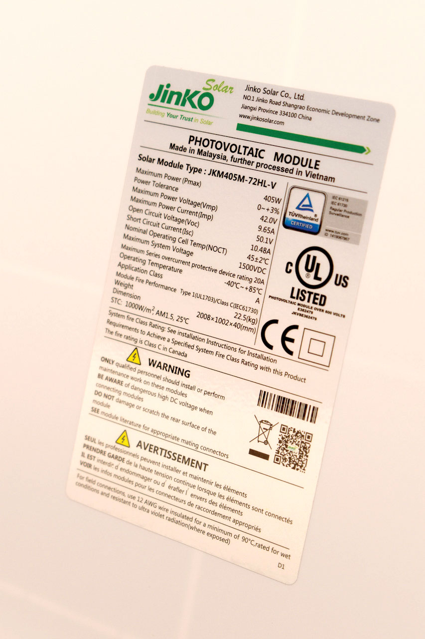
Starting with the photovoltaic (PV) module, it was shown that the output of the PV module is affected by not only the connected load but also the local environment, including the intensity of the sunlight (irradiance) and the temperature of the cells in the PV module. The first look at the PV module should start with the label on the back of the module (photo 1). This label should indicate the certification or listing organization such as UL, CSA, ETL, or TUV. The CE Mark is associated with European requirements and has no bearing on the National Electrical Code (NEC) required certification/listing by one of the OSHA-recognized Nationally Recognized Testing Laboratories (NRTL) listed above (690.4).
The label also indicates that the supplied numerical information has been derived from tests conducted at standard test conditions (STC). These conditions will include an irradiance of 1000 watts per square meter (W/m2) and a cell temperature of 25°C. An air mass (AM) number will also be given but is not generally used in the design and installation of these modules in typical systems. These numbers will be adjusted as shown below to deal with the specific system design and environmental conditions at the installation site.
The Maximum System Voltage (1500 VDC for this module) is one factor that determines how many modules can be connected in series (forming a source circuit or string) and is based on the module Open Circuit Voltage (Voc) at the expected coldest temperature at the installation site. This number is usually 600, 1000, or 1500 V DC and is further modified by any maximum voltage restrictions on the conductors, any electrical equipment such as DC to DC converters, microinverters, inverters, or charge controllers.
The Maximum Series Overcurrent Protective Device Rating (for this module, 20 A) provides a starting point in the selection of conductor ampacities and overcurrent device ratings for the direct current (DC) parts of the system. It should be noted by NEC and UL 1703 Standard requirements that this value must be at least 1.56 times the rated Short Circuit Current (Isc) of the module (in this case, 10.48 A). Note that the condition is met (1.56 x 10.48 = 16.35A, which is less than 20A). Modules not meeting this requirement should not be installed, and the manufacturer and the certification/listing agency should be queried as to discrepancies. As we look deeper, the derivation of the 1.56 factor will be clarified, and the location and additional requirements for this overcurrent protective device will be covered. When properly located in the system, this overcurrent device will protect not only the conductors between the individual series-connected modules in a string or source circuit and the output of those strings to the combiner or other equipment but also the conductors within the module. The overcurrent device, when properly sized, will provide some degree of protection against line-to-line (positive to negative) and, in some cases, line-to-ground faults.
The Maximum Power (Pmax), the Power Tolerance, the Maximum Power Voltage (Vmp), and the Maximum Power Current (Imp) are used in sizing the PV array to meet the overall system requirements. The Module Fire Performance information is used to determine if the module will meet local building and fire code requirements. The Nominal Operating Cell Temperature (NOCT) is used to determine module performance using calculations related to average module operating conditions.
LOOKING DEEPER
DC Conductor Sizing. NEC Section 690.8 establishes the calculations for determining the maximum circuit current for the string of modules or multiple strings of modules connected in parallel. The maximum circuit current (a.k.a. maximum current) is determined by multiplying the short-circuit current from the PV module, strings of PV modules or modules, or strings connected in parallel by 125%. This 125% provides a safety factor because, in some locations, solar irradiance may be as high as 1250 W/m2 (125% of the STC value) for a period of three hours or more (known as continuous duty). This maximum current is used to determine the DC circuit conductor sizes (ampacity) in Section 690.8(B).
Conductor ampacity is determined by one of two methods [690.8(B)]. The larger result from these two calculations shall be used. First, without any adjustment and correction factors, the maximum current shall be multiplied by 125%, and that current is used to determine the conductor size. Note: this 125% is a second 125% and should not be confused with the 125% required in section 690.8(A). This second factor ensures that the conductor does not operate on a continuous basis at more than 80% of rating (0.8 is the reciprocal of 1.25). This is like the 125% of continuous load requirements found in NEC Articles 210 and 215.
The second method applies any adjustment and correction factors for temperature and conduit fill to the maximum current without the second 125% to determine a current value used to calculate the required conductor ampacity or size. The larger conductor size (ampacity) resulting from these two methods shall be used.
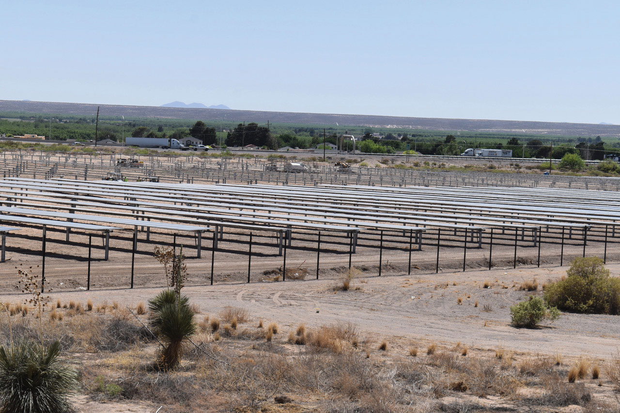
An Example of Conductor Sizing. Here is an example of installing this PV module (photo 1) in a large utility-interactive PV system on a plateau in a Southern California desert. Daytime ambient temperatures can be at 50°C (122°F) for four or five hours at a time on many days of the year. Nighttime temperatures in the winter months can drop to -18°C (0° F), and high winds will keep the modules in the early hours of the morning at that temperature.
The positive and negative output conductors from a source circuit in this PV array will be grouped together with the output conductors from another source circuit, yielding a bundle of four current-carrying conductors in a group. These conductors will be routed along and touching the metal structure of the mounting rack to the DC combiner and, at times, will be in bright sunlight for 10-20 feet.
Section 690.8(B) requires the application of two calculations to determine the ampacity of the conductor.
Applying 690.8(B)(1) to the maximum current of 13.1 A (10.48 x 1.25) yields a value of 16.4 A (13.1×1.25) and using Table 310.17, and the required conductor would be 16 AWG.
Applying 690.8(B)(2) to the maximum current of 13.1 A using the adjustment factors for four conductors in a bundle in free air and an ambient temperature of 50° C and considering a possible temperature addition due to the proximity of the conductor bundle to the metal rack in sunlight yields the following information. With 90°C PV wire/cable and an ambient temperature of 50°C, the temperature correction factor for the conductor is 0.82. Let’s consider the temperature adder of 33°C due to the proximity of the conductor bundle to the metal racking structure (less than 7/8″). The temperature correction factor for this 83°C temperature now becomes 0.29. Table 310.15(C)(1) says that four conductors in a bundle shall have a 0.8 (80%) correction factor. If we take the maximum current of 13.1 A and divide it by the .82 and 0.8 correction factors, we find a required current that the conductor must handle at 30°C is 20 A (13.1/0.82/0.8). With a 90°C conductor from table 310.17, we find that a 16-gauge conductor would be adequate. Note, if such a small conductor were to be found and used (not a common size for PV/Wire cable or USE-2), providing mechanical protection and support for the exposed array conductors would require additional considerations.
It should also be noted that the module operating temperatures and any conductors touching the back surface or any part of the module’s metal frame will be subjected to temperatures that may reach 75°C. If the module cable bundle is subjected to these temperatures, the temperature correction factor from Table 310.15(B)(1) would be 0.50. The resulting ampacity calculation as these conditions of use are applied would be 13.1/0.5/0.8 = 32.75. And by Table 310.17, a 14 AWG conductor would be required.
If we use the more stringent temperature correction factor of 0.29 (for 50°C + 33°C = 83°C) then the calculation is 13.1/0.29/0.8 equals 56.5 A. Table 310.17 would indicate that an 8 AWG cable be required, which has an ampacity of 80A. If we assume that the metal rack will not provide quite the same high heating influence as a rooftop installation, then consideration might be given to installing a 10 AWG conductor, which has an ampacity of 55 A. Also, if the PV cable is also marked XHHW-2, the Exception on 310.15(B)(2) says that this additional temperature correction factor is not needed for such cables. Many PV cables/wires are made with crosslinked polyethylene insulation but may not be marked with the required XHHW-2 designation.
From these two calculations, we must choose the larger conductor [690.8(B)], and more than likely, a 10 AWG conductor will be used. To ensure durability and trouble-free life for the system, a PV cable/wire also marked XHHW-2 would be preferred.
DC Overcurrent Protective Devices
Where and when. On smaller and medium-size systems, the number of strings of modules that can be put in parallel without fuses is of interest. If we assume that there is no source of currents that can back feed from another source like an inverter or charge controller, then typically, one string of modules would require no overcurrent protective device because there is no source of overcurrents that could damage the module or the conductors. From the above, we have seen that the ampacity would probably be at least 1.56 times the short-circuit current, and a conductor this size would easily handle peak currents of 125% of Isc plus a safety factor. Also, two strings could be connected in parallel without an overcurrent device in either string because there’s no place where fault to exist that would allow the currents in the conductor on the module to exceed 125% of the short-circuit current of one string. Currents from the non-faulted string would flow in opposition to the currents in the faulted string and not add together at any location in the conductors.
However, when more than two strings are connected in parallel, it is likely, depending on the exact value of the short-circuit currents and the required maximum protective overcurrent device, that overcurrent devices (typically fuses) will be required in each string. This is because a fault in one string could see the combined short-circuit currents from the other two or more strings which could very well exceed the ampacity of the conductors in the faulted string, or the rating of the maximum overcurrent protective device marked on the back of the PV module. See Section 690.9(A)(1).
When back feed currents are likely from utility-interactive inverters or charge controllers and where a single fuse is protecting two or possibly three strings of modules, the ampacity of the source circuit conductors must be the sum of the single overcurrent device rating plus the sum of all maximum potential currents (1.25 Isc) from the strings protected [690.8(D)]. Even with one string of modules, the potential presence of any back feed currents more than the rating of the module maximum protective overcurrent device or the conductor ampacity will necessitate overcurrent protection for that circuit.
New (for the 2020 NEC) Section 690.9(A)(3) establishes requirements and allowances for overcurrent protection in special circumstances. These requirements are somewhat complex and should be reviewed carefully before applying.
Device Ratings. Section 690.9(B) establishes that overcurrent devices be not less than 125% of the maximum currents in the circuits unless the unlikely situation exists that the overcurrent device in its enclosure as an assembly is listed for continuous operation at 100% of its rating. Rating roundup is allowed. Some electronic devices are listed to prevent back-feeding into the DC array conductors, and those listed devices may reduce the requirements for overcurrent protection in some situations. This 125% is a second 125% and is used to keep the overcurrent device from operating at more than 80% of rating. The combination of the two 125% factors is frequently expressed at 156% (1.25 x 1.25 = 1.56).
A Single Fuse Per Circuit? Although Section 690.9(C) allows a single fuse to be placed in one conductor of each source or output circuit (these circuits are normally ungrounded on the newer systems), consideration should be given to the fact that utility currents under a ground fault in either conductor may back feed through non-isolated inverters. Such backfeed currents may flow in any unprotected conductor. With the proliferation of transformerless (non-isolated) inverters, the author believes that this Code requirement should be reexamined to reflect this hazard. It should be noted that some inverters check only for ground faults at startup and do not detect ground faults during normal daytime operation. The fine print in the inverter warranty should be examined. Also, the AC fuses on the inverter output will typically have a higher rating than those protecting the higher voltage DC conductors in the system and are less likely to blow under an array ground fault situation. Until this situation is more fully examined, a conservative approach is to put overcurrent protective devices in both conductors in each source and output circuit where such overcurrent protection is required. However, this is not currently an NEC requirement.
An Example of an Overcurrent Device Rating. The short-circuit current for the PV module discussed above is 10.48 A. This would also be short-circuit current for a source circuit of these modules connected in series. Applying the 125% factor would yield a minimum overcurrent device rating of 13.1 A, and typically a 15-amp fuse would be used. After the conductor has been selected and the overcurrent protective device selected, it should be ascertained that the overprotected device will protect the conductor under the conditions of use. This is required because the overcurrent protective device may not provide proper protection for the conductor in some unusual situations.
Note that any overcurrent protective device used in the PV DC circuits must be certified/listed as a solar or PV overcurrent device. This certification indicates that the overcurrent protective device has been evaluated for operation up to 50°C, among other conditions, and will be suitable for the outdoor, potentially high-temperature environment of the PV system. Most commonly used overcurrent protective devices are certified/listed for operation only up to 40°C.
Mate-ability of Connectors. In a PV system of any size, there will be multiple modules that are required to be connected in series for each source circuit. Normally these modules will be from the same manufacturer and the same production batch and will have identical, fully matching connectors on the positive and negative output conductors. With fully compatible connectors in the source circuit, compliance with UL standards and NEC requirements for such mate-ability is met. However, when the source circuit input and output conductors need to be extended, careful attention should be made to selecting connectors for the extension conductors that mate with the connectors on the existing source circuit. Just using an MC-4 type connector from one manufacturer with an MC-4 type connector from another manufacturer is insufficient to meet these requirements, even though the two connectors may appear to be mechanically and electrically compatible.
This mating requirement ensures that the electrical and mechanical parameters of all paired connectors are identical and compatible and have been certified/listed as such. At this time (early 2022), the best way to meet this is to use connectors to extend the source circuit cables that are identical in manufacturer and product number to the connectors that are used on the modules. This information should be found in the module installation instructions.
A NEMA (National Electrical Manufacturers Association) standard is being developed, which will be a production standard for a uniform PV connector. When available and used by all manufacturers, it will result in much easier and safer connections in the DC circuits associated with the PV modules and the source circuits. Current safety standards used to certify/list connectors do not evaluate the compatibility between different brands and production lines of connectors for full mechanical and electrical compatibility over the life of the product. A NEMA production standard will establish the requirements so that connectors made and certified to the production standard will be compatible from brand to brand.
Summary
This PV Forest has trees that are fairly close together at this point in our move into the forest. Understanding the basis for the NEC requirements to deal with the somewhat unique characteristics of PV modules and systems and how to apply these requirements will take some time. And as we will see in the next article, the forest will be getting denser.
In the next article in this series, the cold weather open-circuit voltage of this module will be calculated for the environment specified, and the number of modules to be connected in series for each source circuit will be calculated based on the inverter specifications. The DC combiner will also be examined.