Somewhat like Juliette looking for Romeo, PV installers and a few inspectors have trouble looking for, finding, and interpreting the numerous disconnect requirements in the National Electrical Code that apply to PV systems. The application of these requirements, even when located, is somewhat complicated by the fact that some PV equipment includes some of the required disconnects and some does not. Also, the placement of the equipment containing those disconnects is a determining factor in whether or not, the internal disconnect meets Code requirements. As in all other things related to the NEC, the local utility, the local jurisdictional code, and/or the AHJ may impose other or differing requirements. The following information will attempt to shed some light on the various disconnect requirements; however, don’t expect anything approaching the prose of the Bard of Avon.
The Basic and General Disconnect Requirements
There are several sections of Code that deal with the PV system disconnect requirements. In some cases, they refer to dc disconnects; in other instances, they refer to PV system disconnects; and it is sometimes difficult to determine whether they apply to ac circuits, dc circuits, or both. There are continuing efforts in the development of the NEC requirements for PV systems to more narrowly define a PV system as only the PV modules, the dc circuits, and the utility-interactive inverter. Batteries and ac output circuits, in the future, may be considered as separate parts of the power system. Stand by for the 2017 NEC, but for now:
690.13 Building or Other Structure Supplied by a Photovoltaic System. Means shall be provided to disconnect all ungrounded dc conductors of a PV system from all other conductors in a building or other structure.
(A) Location. The PV disconnecting means shall be installed at a readily accessible location either on the outside of a building or structure or inside nearest the point of entrance of the system conductors.
Exception: Installations that comply with 690.31(G) shall be permitted to have the disconnecting means located remote from the point of entry of the system conductors.
Note the similarity of these sections relating to dc PV disconnects to the service-entrance disconnect requirements in Article 230.
230.70 General. Means shall be provided to disconnect all conductors in a building or other structure from the service-entrance conductors.
230.70(A)(1) Readily Accessible Location. The service disconnecting means shall be installed at a readily accessible location either outside of a building or structure or inside nearest the point of entrance of the service conductors.
The allowance for these disconnects to be outside or inside the building at the point of first penetration does create some options in our choice of disconnect location, and various jurisdictional requirements may influence that location. For example in some states, the ac service disconnect on new dwelling units must be outside the building.
And as noted below, various other requirements and exceptions for PV disconnects allow for a wide variation in the location of those disconnects.
In the case of PV systems, we have several different types of equipment such as inverters and charge controllers that are supplied by multiple sources of energy, and the disconnect requirements have to address that situation.
690.15 Disconnection of Photovoltaic Equipment. Means shall be provided to disconnect equipment, such as inverters, batteries, and charge controllers, from all ungrounded conductors of all sources. If the equipment is energized from more than one source, the disconnecting means shall be grouped and identified.
Working Backward from the AC Utility Point of Connection
With the exception of standalone PV systems, the utility interactive PV systems will eventually connect to the utility power source (the grid). We have two methods of connecting the output of the utility interactive inverter to the utility grid. They are as allowed in NEC 705.12(A) for supply-side connected PV systems and in 705.12 (D) for load-side connected PV systems.
Supply-Side Connected PV Systems
If we consider a single utility interactive inverter connected to the utility, it will be connected through a PV ac disconnect and from that disconnect to a connection point on the supply side of the main service entrance disconnect for the building or structure.
In many ac circuits, a disconnect is frequently combined with an overcurrent device in the form of a circuit breaker. Also, a bladed disconnect (safety switch) is frequently used as an ac PV disconnect to meet utility requirements that will be discussed below.
The National Fire Protection Association (NFPA) has defined the circuits from the PV inverter to the supply side point of connection as feeders, and they have re-enforced this definition by requiring, in the new (for the 2014 NEC) Section 705.31, that an overcurrent protective device (OCPD) be installed within 10 feet of the connection point to the existing service-entrance conductors or that there be an overcurrent protection of that connection point. The existing service-entrance conductors, their type, their location, and their accessibility will determine whether or not the ac PV disconnect/overcurrent protection can be installed within the 10 feet requirement, or that it must be installed at a further distance with the overcurrent devices listed in the Exception (cable limiter or current-limiting circuit breaker) be installed at the connection point. The PV installer will have to determine the best combination of equipment to meet the requirement for any particular installation.
Since the available fault currents on the service-entrance conductors and the currents on the PV supply-side connection circuit can be high and are not protected by an overcurrent device (except on the primary of the distribution transformer), it is common sense that either the cable limiters or the current-limiting circuit breaker be installed at the tap point or that the ac PV disconnect/overcurrent device be installed as close to that connection as possible to minimize potential damage to these unprotected circuit conductors.
Where is the source?
In circuits where there are two sources of power, for example, a utility connection on one end of the circuit and a utility interactive inverter on the other end of the circuit, it is sometimes difficult to determine where the overcurrent devices should be to protect that circuit. On ac circuits, since the overcurrent device is frequently combined with the disconnect function in a circuit breaker, this discussion is appropriate at this time.
Section 690.9 (A) was revised for the 2014 NEC as shown with the underlined material below in an attempt to clarify this situation. The intent of the revision, unfortunately, didn’t quite come out the way it was proposed (by me). It was to require that if a circuit has two sources—with one at either end—the overcurrent device protecting the circuit should be placed near the end (source) that has the highest available fault current. In the case of the current-limited, utility-interactive inverter on one end of a circuit and a utility source with very much higher available fault currents on the other end, the overcurrent device protecting that circuit should be located at the utility source end. Oh well, sometimes the true intent of the proposal gets lost in the code-making process.
690.9 (A) Circuits and Equipment. PV source circuit, PV output circuit, inverter output circuit, and storage battery circuit conductors and equipment shall be protected in accordance with the requirements of Article 240. Protection devices for PV source circuits and PV output circuits shall be in accordance with the requirements of 690.9(B) through (E). Circuits, either ac or dc, connected to current-limited supplies (e.g., PV modules, ac output of utility-interactive inverters), and also connected to sources having significantly higher current availability (e.g., parallel strings of modules, utility power), shall be protected at the source from overcurrent.
It should be noted that this location of the overcurrent protection for a circuit may not alleviate the need for a disconnect at the opposite end of the circuit. An example would be a dc circuit between the batteries and an inverter where these devices are in separate rooms. A disconnect would be required, generally, at each end of the circuit; but an overcurrent device would be required only at the battery end.
Load-Side Connected PV Systems
Utility-interactive PV systems connected to the load side of the main disconnect are usually connected through a backfed breaker in the main panel or through one or more backfed breakers in a subpanel (sometimes an inverter ac combing subpanel) which is then, in turn, connected to a backfed breaker in the main panel.
Where the PV inverter is located in close proximity (as determined by the AHJ) to the backfed breaker in the panel, that backfed breaker could serve as both the ac PV disconnect as well as the maintenance disconnect required by 690.15 (above). Where the PV inverter is not within sight or in close proximity to the backfed breaker, an ac disconnect may be required at the inverter location to provide the maintenance disconnect from the ac source. This is particularly true when the inverter is inside the building and the load center housing the backfed breaker is on the outside of the building or vice versa.
While many inverters have an internal dc disconnect for the PV circuits, frequently they do not have an internal ac disconnect, and an external ac disconnect typically in the form of the circuit breaker may be required.
Don’t Forget Those Non-Code UtilityRequirements
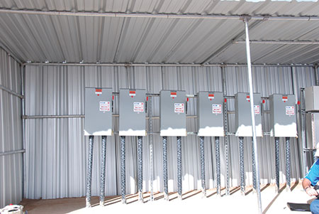
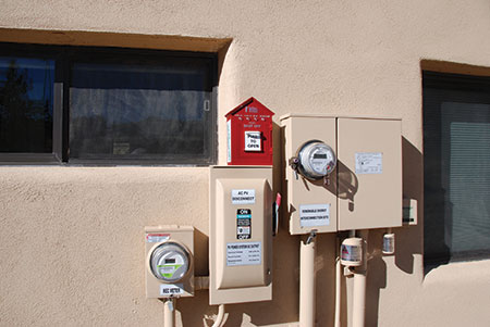
Most utility companies require an exterior, readily accessible, visible-blade, lockable-open safety switch in the output of the PV system between the inverter and the point of connection to the service. See photo 1. This utility requirement applies to both supply-side connected PV systems and load-side connected PV systems, and this requirement is not in the NEC. The utility requirements will generally specify the location of this disconnect and in many cases it is required to be within some specified distance of the existing revenue meter or from the main service disconnect.
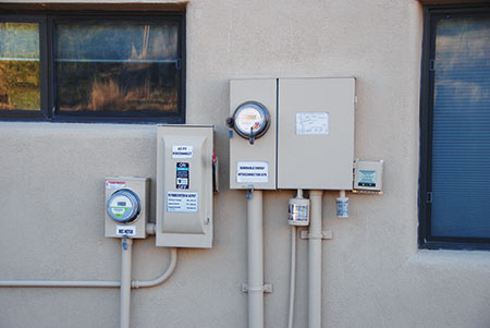
The utility company may also require a PV production meter [aka, a renewable energy credit (REC) meter] in this same circuit, and again, the meter is not a Code requirement. The utility will determine in which order these two devices are to be connected. In some cases, the safety switch is on the inverter output and the meter is nearer the utility point of connection; and in other jurisdictions, the connections are reversed with the meter closer to the inverter output and the safety switch closer to the point of utility connection.
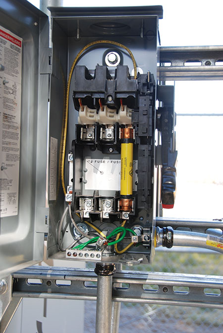
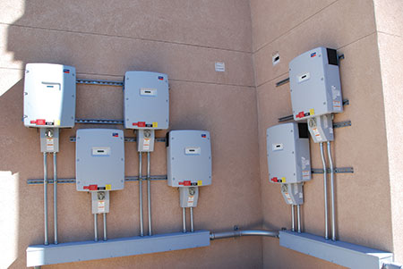
If the safety switch is not locked by the utility, it can usually be used as either the inverter maintenance switch or the ac PV disconnect switch or both, again depending on the relative position of the inverter, the safety switch, and the backfed breaker in the main panel. See photo 2.
Utility-Interactive Inverters on the Roof
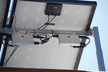
In installations using microinverters on the roof or commercial installations where the “string” inverters are located on the roof of the building, the Code, in 690.15(A), has specific disconnecting requirements related to those types of installations where the inverters are located in not readily accessible areas. While this section is self-explanatory, some additional information is needed when it comes to microinverters. To meet the disconnect requirements at the inverter location, most microinverter companies have had their ac and dc connectors listed as load break rated disconnects when used in this application. This information should appear in the instruction manual for the particular product and is covered in the Code by 690.33(E). See photo 3.
AC PV Modules and Microinverters
At the present time, ac PV modules and microinverters are the only types of inverters that are paralleled at their outputs on a common circuit (called the trunk cable) without a dedicated overcurrent protection device for each inverter. As the power rating of these devices increases, some more precise definition of these inverters will be needed in the Code because the power levels of these smaller microinverters are approaching the “string” inverter power levels.
Because the ac connectors are listed as load break connectors at each microinverter, there is no requirement for an additional ac disconnect for the trunk cable on the roof. In many cases, several trunk cables (or their extensions using an appropriate wiring method) from sets of microinverters or ac PV modules are run from the roof to an ac inverter combining subpanel in a readily accessible area where each of the backfed breakers for each of the sets of microinverter outputs serves as the second ac disconnect required by 690.15(A).
Stand-Alone PV Systems
In the larger stand-alone systems that are used to power dwellings or other structures, the ac output of the inverter is normally fed to a power distribution panel. This power distribution panel should have a main breaker, and that breaker is equivalent to the main ac service disconnect on utility connected electrical systems. NEC 690.10 provides limited guidance on the requirements for disconnects and their location. If the inverter is in the interior of the house, there appears to be no specific location for the main ac disconnect. However, AHJs who inspect such systems, sometimes give consideration to requiring an external ac disconnect on the dwelling or at least a directory on the outside of the building indicating the location of the ac disconnect inside the building. When the inverter is located in a separate structure or is exterior to the dwelling, then the normal code rules for installing an ac disconnect for the conductors entering the building or structure would apply. In some jurisdictions, the Fire Service may have established requirements for disconnects on stand-alone PV systems.
The DC PV Disconnect
The PV array for both utility-interactive and stand-alone PV systems will be outside the building or structure and, in most cases, the dc circuits from that PV array will have to enter the building. Section 690.13, 690.13(A) and the Exception govern the location of the PV dc disconnect. Using a metallic raceway or a metallic cable assembly through the building will essentially allow the PV dc disconnect to be located at an accessible location anywhere inside the building except in a bathroom. Section 690.13(E) establishes that a disconnect is not required on the roof or at the PV location. However, Section 690.15(D) requires that the output of any dc combiner located on the roof have a disconnect at its output.
Evidently, through the use of master keys and fire axes, the Fire Service considers the interior of a locked home to meet the readily accessible requirement, since about half of the homes in the United States have the main ac service disconnect located inside the structure. In the future, some consideration should be given to the differences between an ac service and a dc PV circuit entering a building with respect to disconnect requirements.
The currently evolving changes in the Code and in the UL standards for NEC 690.12 Rapid Shutdown System for PV Systems may have some impact on how the PV system can be controlled from a single point in an emergency situation. See photo 4.
Many utility-interactive inverters have an internal dc disconnect or one attached to an enclosure that is attached to the inverter. If the inverter has the dc disconnect in a separate enclosure from the inverter proper and is located in an area that meets the PV dc disconnect requirements, then the AHJ may allow the inverter/disconnect combination to be used as the PV dc disconnect and the dc maintenance disconnect for the inverter. See photo 5.
Summary
Disconnect requirements with respect to location vary significantly with each particular PV installation. Those requirements are being modified for clarity and addressing new equipment in each new edition of the NEC. To paraphrase the Bard again: We know what disconnects are, but know not what or where they may be.
For More Information
The author has retired from the Southwest Technology Development Institute at New Mexico State University, but is devoting about 25% of his time to PV activities in order to keep involved in writing these “Perspectives on PV’ articles in the IAEI News and to stay active in the NEC and UL Standards development process. Seven to eight-hour presentations are still available on PV and the Code; and they cover 2008–2014 NEC requirements. He can be reached at e-mail: jwiles@nmsu.edu, phone: 575-646-6105