Photovoltaic power systems, like other electrical power systems, require overcurrent protection for conductors, bus bars, and some equipment. However, some of the electrical sources in PV systems are unique when compared with the typical utility source provided by the utility grid. Also, some of the equipment in a PV system operates in a different manner than normal ac load electrical equipment. These differences between PV systems and the normal ac electrical system in a residence or commercial building should be examined before we get into a detailed discussion of the overcurrent protection for the PV circuits.
Sources of Energy
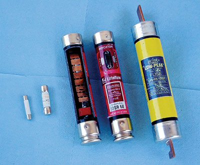
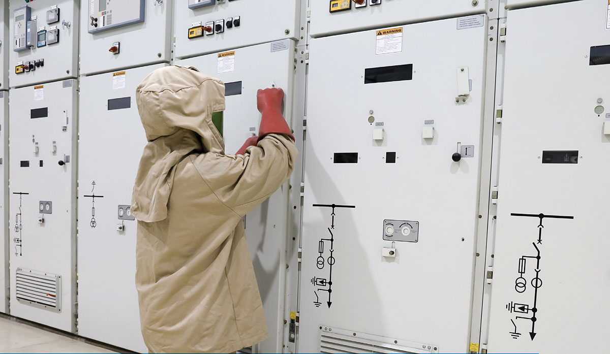
AC Utility. In the typical ac circuit in a residence or commercial building, the utility provides high levels of energy from the local distribution system. The available fault currents from a utility service are substantial compared to the typical fault currents that are available in a PV system. Molded case circuit breakers used in ac load centers both at the branch circuit level and the main breaker level have interrupt capabilities of 10,000-A; 22,000-A; 65,000-A and higher. Fuses used on these circuits have interrupt capabilities even higher to deal with the very high available fault currents from large distribution transformers. See the lead-in photos.
These available ac fault currents may be calculated using parameters provided by the utility company for the distribution transformer and knowledge of the circuit impedance from that transformer to the point where the fault currents are to be interrupted. See “Calculating Fault Current” in the May-June 2015 IAEI News. A nominal ac line voltage is used in most code calculations. The National Electrical Code (NEC) requires in Section 110.9 that the interrupt rating of overcurrent protection devices be at least equal to the available fault current at the terminals of those overcurrent devices.
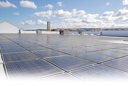
DC PV. In a PV system, the source of energy is usually considered to be the PV module, and PV modules have operating currents (Imp for maximum power current) in the 2 to 12 amp range depending on the size of the cell in the module and the configuration of the internal PV module wiring. Note that these currents are increasing as module size increases and cell technology improves. Modules are typically connected in series strings where the operating current of the string remains the same as that of an individual module, but the string voltage increases to maximums as high as 600, 1000, and in some newer utility-scale systems 1500 V. The strings of modules are connected in parallel to increase the operating current and on larger utility-scale systems, these combined string and subarray currents may reach 1000 A or higher. See photo 1.
The operating current is not the worst-case current that a PV module can generate. The worst-case current is known as the short-circuit current (Isc) of the module. PV modules, PV strings, PV subarrays and PV arrays (unlike the typical ac circuit) can be short-circuited (using appropriate equipment and with due caution) without damage to the modules or the connecting electrical circuits when those circuits have been properly designed. The short-circuit current of a module may only be 10 to 15% greater than the operating current of the module. With a module having an operating current of 12 A, for example, the available short-circuit current may be only 15 A.
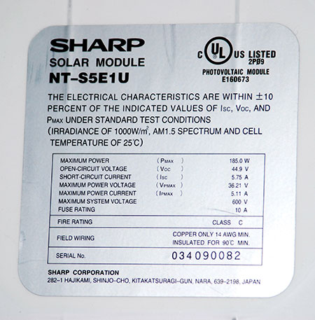
Both the operating current and the short-circuit current of a module are not fixed, but vary with the available sunlight and to a lesser extent with the temperature of the module. Ratings for both of these currents are marked on the back of the PV module and these are stated at a set of internationally accepted Standard Test Conditions (STC) that are a sunlight intensity (irradiance) of 1000 W per square meter (W/m2 ) and a cell temperature of 25° C (77° F). See photo 2.
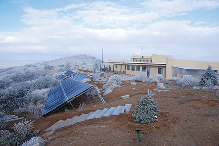
Additionally, the module string and array operating voltages (Vmp) and the open-circuit voltages (Voc) vary with irradiance and temperature (Photo 3).
These variations in voltage and current on the output of a photovoltaic power system result in more complex code calculations for fault current protection and overcurrent protection than is normally found in the typical ac circuit calculations for the same parameters.
Sources of Fault Current
In most ac power circuits, the utility source of energy becomes the source of the overload or fault currents, and the current in a circuit usually flows from the utility source to the load. The requirements in NEC Section 240.21 can be followed where circuits are protected from overcurrents where they receive their supply—the utility end of the circuit.
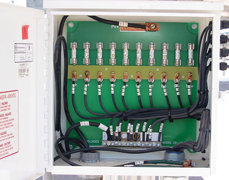
However, in dc PV circuits the PV modules have limited current even when short-circuited under fault conditions. This limited current also applies to the strings of series-connected modules and to some extent the subarray output circuits where several strings of modules are connected in parallel. As we move from the modules to the strings to the output of parallel-connected strings forming subarrays to the output of parallel connected subarrays into the output of the entire array, the available currents that could contribute to faults and overloads increase. As these currents increase, the circuit conductors are increased in size appropriately, and the ratings of overcurrent devices are also increased. See photo 4.
The source of potentially high overload currents and fault currents is not the PV module or the string of PV modules; it is the combined output of those strings in parallel and the combined output of subarrays connected in parallel that pose the source of overload and fault currents.
The change shown below was added to the 2014 NEC in Section 690.9(A) to address this peculiarity of current-limited sources; however, the intent of the submission was not fully implemented.
Protection devices for PV source circuits and PV output circuits shall be in accordance with the requirements of 690.9(B) through (E). Circuits, either ac or dc, connected to current-limited supplies (e.g., PV modules, ac output of utility-interactive inverters), and also connected to sources having significantly higher current availability (e.g., parallel strings of modules, utility power), shall be protected at the source from overcurrent.
The change should have included the final words “shall be protected at the source of the highest fault currents that can damage the circuit.” A revision for the 2017 NEC has been proposed to rectify this omission.
With current-limited sources such as PV modules and the ac output of utility interactive inverters, the location of the overcurrent device for the circuits is going to be located at the source that has the highest available fault current.
Overcurrent Device Ratings
Current. To address the varying operating currents and short-circuit currents of a PV system, the overcurrent device ratings and conductor sizes are subjected to additional calculations based on the worst-case values of current and voltage that can be generated by the modules. The available short-circuit currents (Isc) from PV modules represent the worst-case currents that the circuits can be expected to sustain for long periods of time (three hours or more). These short-circuit currents vary with irradiance and to a lesser extent the temperature of the PV cell/module. As the irradiance gets stronger, the available short-circuit current increases. Increasing temperatures affect short-circuit current slightly and are usually ignored. The Standard Test Condition value of irradiance at 1000 W/m2 is an average irradiance at sea level on the surface of the earth. Because the STC value of irradiance can be exceeded for extended periods of time in very clear weather and at higher altitudes, the PV industry has established a 125% safety factor on calculations involving the short-circuit current of a module rated at those conditions. The 125% safety factor represents a potential irradiance of 1250 W/m2 , and there have been few, if any, measurements of irradiance for three hours or more that have exceeded this value.
Overcurrent device current ratings in dc circuits involving the output of the PV module, the PV string, or the PV array are based on the short-circuit current at a particular point in those circuits. The short-circuit current is multiplied by a factor of 125% to address the varying irradiance possibilities as required by NEC Section 690.8 and then the requirements of NEC Section 690.9(B) are applied where an additional 125% is applied to the calculation. This second 125% is this same 125% required in feeder calculations by NEC Section 215.2(A)(1) for continuous loads and by 210.19(A)(1) for branch circuits. DC PV currents from the modules are considered continuous, and there are no non-continuous currents. Recent changes in the NEC require that the conditions of use factors be applied where they are more severe than the second 125% factor, but that is a discussion for another article.
Voltage. The voltage rating of overcurrent devices in PV dc source and output circuits (defined in 690.2) is based on the requirements of NEC Section 690.7. That section requires that the maximum system voltage be calculated and used in determining the voltage rating of all equipment including overcurrent devices. That maximum system voltage is a function of the ambient temperature in which the circuit will be operating. As the temperature decreases below the Standard Test Condition value of 25° C (77° F), the open-circuit voltage increases, and this maximum, cold-temperature voltage is used for the voltage rating of overcurrent devices.
Location, Location, Location
Direct-current combiners are used to combine strings of PV modules into a single output or combine those outputs with an additional combiner into a subarray output and then, in the larger systems, a third combiner(s) is used to combine the several subarrays into the array output. At each point where multiple outputs are combined, the operating currents and the available fault current will increase at these locations. In these combiners, each input circuit has an overcurrent device to protect the individual input, which will have lower current (and smaller conductors) than the combined output circuit. These input circuits are thereby protected from those higher combined output currents should there be a fault in one of the input circuits. See photo 5.
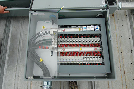
DC combiners that are combining the output of several strings of modules will have the overcurrent devices, usually a fuse, mounted in a “finger safe” fuse holder that allows the fuse to be serviced when not under load in a safe manner (690.16). On some low voltage (12-48 volts) systems, molded case circuit breakers are used in the combiners instead of fuses. NEC Section 690.15(C)(2014) requires that the dc combiner have a disconnect at or near its output and that disconnect will facilitate the servicing of overcurrent devices in the combiner by creating an open circuit, no-load condition, and isolating the combiner from other “downstream” energized circuits such as the outputs of other combiners or inverter dc inputs. NEC Sections 690.16 and 690.18 establish other criteria for safe maintenance of overcurrent devices.
Unusual situations are found in PV systems
No fuse required. A single string of modules may be connected to a utility-interactive inverter without overcurrent device if the available backfeed fault current from the inverter is less than the maximum series overcurrent device marked on the module label [690.9(A) EX].
Possible cost savings. Two strings of PV modules may be connected to a single utility-interactive inverter input without an overcurrent device if the inverter cannot backfeed currents into the dc array wiring. The amount of inverter backfeed current, or lack thereof, is (or should be) included in the inverter specifications.
The output of two strings of PV modules may be paralleled and connected to a single overcurrent device under a limited number of conditions [690.8(D)]. The module and string conductor ampacity and the maximum series overcurrent device marked on the module label must be greater than the rating of the single fuse plus 1.25 Isc. That fuse will have a minimum rating of 2 x 1.25 x 1.25 x Isc = 3.125 Isc.
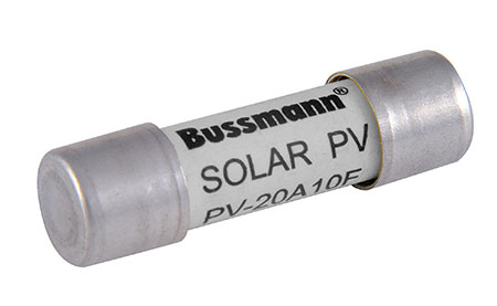
Heat is a no-no. The temperatures inside dc combiners that are mounted where exposed sunlight on the roofs of buildings will frequently exceed the 50°C maximum operating temperature of listed PV fuses [690.9(D)]. See photo 6. Fuses that are not listed for PV (found in installations installed before the 2014 NEC came into effect) usually have a temperature limit of only 40°C, and that temperature may be exceeded on rooftops even in shaded locations. In both situations, it may be necessary to mount these dc combiners in conditioned spaces or, at the very least, in areas not subject to the heat bubble found on roofs and not with direct exposure to sunlight.
This limitation also applies to fuses that are mounted in in-line fuse holders that are intended to be installed in the exposed module interconnecting cables. Sunlight may increase the temperature of the fuse beyond the listed limit of 50°C.
Equipment Protection. Harry, the electrician, is installing a PV system with a 2500-watt, 240-volt inverter that has a rated output current of 10.4 amps. Multiplying by the required 125%, he gets a required OCPD of 13 amps and knows that he can round that up to 15 amps and use a 14 AWG conductor. However, the run to the backfed breaker in the main panel is long, and Harry upgrades the circuit to a 12 AWG conductor to keep the voltage drop low. He has only a position with a 20-amp breaker available in the panel and decides to use that. Unfortunately, Harry did not read all of the instructions in the inverter installation manual, one of which specifies that the maximum external overcurrent device on the ac output is limited to 15 amps.
This restriction is in the inverter manual because UL Standard 1741 allows the manufacturer to use an external overcurrent device to protect internal inverter conductors and components. Unfortunately, this is a code violation [110.3(B)].
Equivalent Protection. Fuses and circuit breakers, with the same ratings, are equivalent in terms of providing overcurrent protection and may be used interchangeably unless the Code or the device instruction manual specifies otherwise. PV module labeling is changing from “Maximum Series Fuse is XX” to “Maximum Overcurrent Device, If Required, is XX”. But, note that the overcurrent device used in dc PV source and dc PV output circuits must be listed for use in PV systems [690.9(D)]. See photo 6.
Summary
PV systems have some unique features that make the application of overcurrent devices somewhat different than their application in conventional ac circuits. The modules and the utility-interactive inverters are current-limited. These current limits generally indicate that the overcurrent protection for the circuits connected to the outputs of these devices be protected from overcurrents and fault currents at the external, usually significantly larger, source of these overcurrents and fault currents. With PV modules, both the voltage and current outputs, while rated at a set of standard test conditions, vary significantly with solar irradiance and temperature. Additional calculations on the ratings of overcurrent devices are required to meet NEC requirements.
For More Information
The author has retired from the Southwest Technology Development Institute at New Mexico State University but is devoting about 25% of his time to PV activities in order to keep involved in writing these “Perspectives on PV’ articles in the IAEI News and to stay active in the NEC and UL Standards development process. Seven- to eight-hour presentations are still available for PV and the Code, and they cover 2008–2014 NEC requirements. He can be reached at e-mail: jwiles@nmsu.edu, phone: 575-646-6105
The Southwest Technology Development Institute web site maintains a PV Systems Inspector/Installer Checklist and all copies of the previous “Perspectives on PV” articles for easy downloading. A color copy of the latest version (1.93) of the 150-page, Photovoltaic Power Systems and the 2005 National Electrical Code: Suggested Practices, written by the author, may be downloaded from this website: http://www.nmsu.edu/~tdi/Photovoltaics/Codes-Stds/Codes-Stds.html



Find Us on Socials