Introduction
As photovoltaic power (PV) systems become increasingly common due to an increasing awareness of climate change issues, including severe storms and very large forest fires, both new and seasoned code enforcement people sometimes get buried in a forest of trees dealing with code minutia and issues. Periodically, it is beneficial for all involved to backup and look at the PV electrical system from a larger perspective. In this article, that perspective will include the various types of PV systems and the equipment and components that comprise them.
The Basics
There are several different configurations of PV systems that the inspector will face during their career. They include off-grid (not connected to a utility) systems in small residential versions as well as larger commercial versions. They also include utility-interactive systems from the small residential system to the very large utility-scale systems. They include systems that have both utility interaction and energy storage, again from small systems to very large systems.
A Brief Historical Summary. In the early 1970s, PV module prices became somewhat affordable to the average individual ($10-$20 per watt). One of the first major US PV module manufacturing plants was in Southern California and was owned and operated by a petroleum company [Atlantic Richfield Company (ARCO)]. A web search will reveal the interesting history of the beginning of PV module production in the United States. The modules were initially made with a nominal 12-volt direct current (V DC) output that was intended to charge 12-volt (V) automotive batteries in off-grid applications. These early PV modules were very popular in Northern California, where many citizens wanted power in remote areas to power water pumps and operate grow lamps.
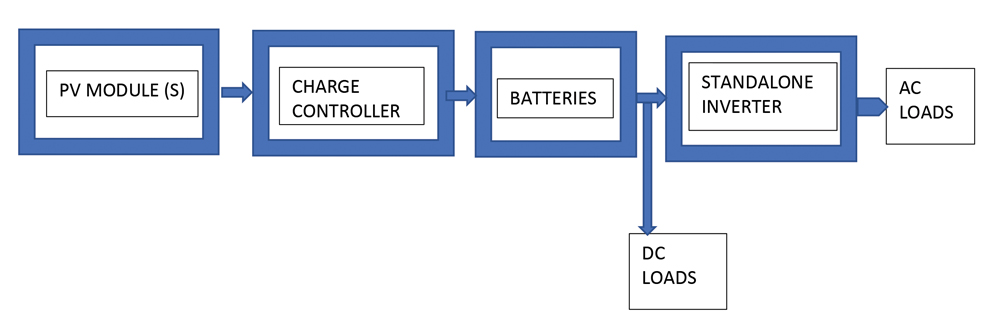
Other companies such as SOLAREX were also early producers of PV modules in the US. Figure 1 illustrates a one-line block diagram, with no detailed NEC requirements shown, of an off-grid PV system (aka stand-alone PV system). The main components include the PV modules, a charge controller, an energy storage system (batteries), and direct-current loads. In a few years, innovative companies begin to produce inverters capable of taking the 12 V DC and later the 24 to 48 V DC battery output and converting it to 120 V, 60 Hz (cycle) alternating current (AC). These off-grid PV systems are still common for remote homes, instrumentation sites at hydrocarbon production wells, national parks in remote areas, power for remote villages for lighting and water pumping, and even radar speed traps.
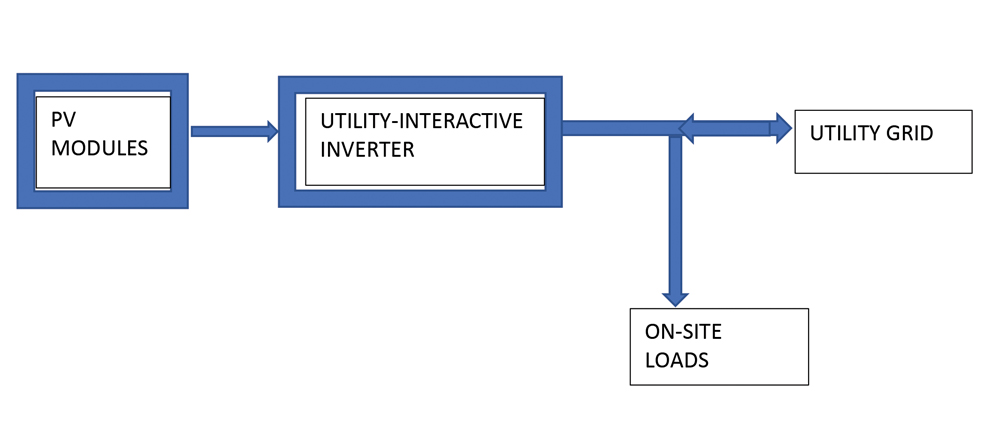
In the early 1980s, the US Department of Energy (DOE) made a pronouncement that photovoltaic electrical power was going to be “too cheap to meter.” DOE established research facilities at universities here in New Mexico (Southwest Region Experiment Station – now the Southwest Technology Development Institute), in New England, and in Florida. Photovoltaic research programs were also established at the national labs, including Sandia National Laboratories and the Solar Energy Research Institute (now the National Renewable Energy Laboratory). The focus of these organizations was primarily utility-interactive photovoltaic power systems using the newly developed utility-interactive inverter that could change the DC output of the PV array into 120/240 V and higher alternating current. See figure 2 showing a one-line block diagram of a basic utility-interactive PV system, again with no code requirements. Most PV systems (in terms of kilowatts and megawatts) being installed nationally and internationally are utility-interactive systems.
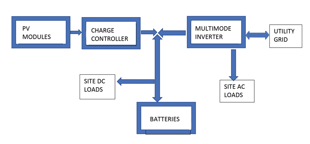
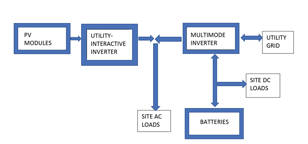
As the reliability of the equipment improved and the costs came down, more complex systems were developed. These systems are becoming quite common and in demand where utility power is interrupted frequently due to utility power curtailments to avoid starting forest fires or utility transmission line damages due to severe storms, including forest fires. The system is a utility-interactive system that includes energy storage (aka battery backup) for periods when the utility power is unavailable. Figure 3 shows one of these types of systems using direct–current coupling of the various components. Figure 4 shows another version of these battery-backed-up systems using alternating-current coupling of the various components. Both systems have advantages and disadvantages, and both are in use today in sizes ranging from small residential applications to large utility-scale applications.
Looking Deeper
The PV module: FIGURES 1, 2, 3, and 4.
The voltage and current output of a PV module are dependent on several factors. Knowledge of these factors and how they change is critical in designing a PV system and inspecting that PV system for compliance with the National Electrical Code (NEC). The intensity of sunlight, known as the irradiance, falling on the cells in a PV module is the primary driver on the electrical output. The greater the intensity of the sunlight, the more power the PV module can produce. The output is determined by several factors, including irradiance. PV modules are evaluated and tested during the listing process (for safety by a Nationally Recognized Testing Laboratory) at a set of standard test conditions (STC). The standard test condition for irradiance is 1000 watts per square meter. The standard for cell temperature is 25°C.
Power and Irradiance. At the standard test conditions, if the module is properly loaded, it will deliver its rated peak power to that load. Variations in these two parameters (irradiance and load) will affect the output of the PV module. Decreases in the irradiance from the standard test condition will lower the peak output of the PV module. Both voltage and current will be affected. In all cases, the output of the PV module will be significantly affected by the load placed on the PV module.
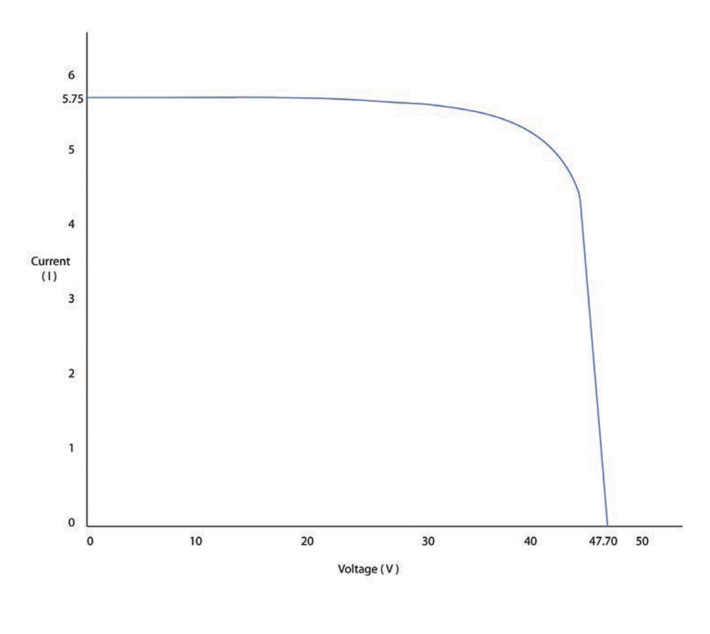
Output vs. Load. If the load were reduced to zero (effectively an open circuit on the output), the voltage measured would be the open-circuit voltage (Voc). The current measured would obviously be zero at an open-circuit condition. Conversely, a short-circuit applied to the output of the PV module would result in the short-circuit current (Isc) being measured with zero output voltage. In either of these test conditions, the values measured will depend on the intensity of the sunlight (irradiance). As the load is changed from an open-circuit condition to a short-circuit condition, the voltage and current values will vary accordingly. Figure 5 shows a module performance characteristic curve known as the IV curve and is typically measured at standard test conditions with the connected load changing from a short circuit (current but zero voltage) to an open circuit (voltage but zero current). The short-circuit current is at the left end of the curve, and the open-circuit voltage is at the right end.
Temperature Effects. In addition to the module output varying with irradiance and load, the voltage and current outputs also vary with temperature. For any particular point on the IV curve (determined by the load on the module), the voltage measured will increase with decreasing temperatures. Conversely, increasing temperatures will result in a lower measured voltage. Knowledge of this characteristic is critical in determining the maximum number of modules that will be connected in series to form a source circuit (aka a string) that will not damage switchgear, inverters, or other equipment during very cold weather. Section 690.7 of the NEC establishes the requirements.
Table 690.7 in the NEC may be used as an approximation of the voltage variation with respect to temperature for crystalline and polycrystalline PV modules. The multiplication factor in Table 690.7 for any particular low temperature is applied to the rated open-circuit voltage at standard test conditions to determine the open-circuit voltage for the module or source circuit at that selected low temperature (usually the expected lowest temperature at the installation location).
The current from a PV module is also affected by temperature but to a much lesser degree than voltage. Current increases very slightly with increasing temperature and decrease very slightly with decreasing temperature. In many small and medium-sized PV system designs, this current variation with temperature is not considered critical. However, the module short-circuit current at STC is used to size conductors, overcurrent protection, and switchgear (690.8, 690.9). For other types of module cell construction such as Cadmium Telluride (CdTe), Copper Indium Selenium (CIS), or amorphous silicon, factors or coefficients of temperature for voltage, current, and power should be used to calculate these parameters at various temperatures. These coefficients will be found in the PV module datasheet.
It should be noted that the combined effects of voltage and current on the output of the PV module as a function of temperature result in the module maximum power output decreasing as the module temperature increases. At typical module operating temperatures of 65 to 75°C, with an ambient temperature of around 40°C (104°F), a module may have its maximum power reduced by 25% from the rated power at standard test conditions.
The Charge Controller: Figures 1 and 3. A state-of-the-art charge controller will automatically load the PV array in a manner that extracts the maximum power from that PV array under a wide variety of irradiance and temperature conditions. This loading is varied automatically and is known as peak power tracking. Internally, the charge controller will convert the widely varying DC voltage from the PV array to a voltage that can be used to charge the connected battery system. Independent of the peak power tracking, the charge controller will also provide optimum charge regulation for the battery, including a bulk charge stage at maximum available current, a full charge mode at constant voltage with decreasing current as the battery reaches full charge, and a float charge mode where the battery is maintained at full charge at a constant voltage. For flooded lead-acid batteries, the charge controller will also provide a periodic equalization charge at a voltage higher than the float voltage to keep the electrolyte well mixed to prevent stratification.
In the older 12 V PV off-grid systems, the 12 V PV module normally had a peak-power voltage of about 17 V. This voltage was converted by the charge controller to the appropriate voltages required to charge a 12 V nominal lead-acid battery. There are currently off-grid PV systems that operate with 24 V, 48 V, and higher battery voltages. An appropriate charge controller must be used that converts the PV input voltage to the voltage required by the battery bank. There are now charge controllers that accept PV outputs up to 600 V and convert those voltages down to the requirements to charge a 48 V battery bank. These types of charge controllers are sometimes useful in converting a utility-interactive PV system that has voltages in the hundreds of volts to a system that can use batteries for storage at a much lower voltage.
The very large utility-scale PV systems that have energy storage systems typically use lithium-ion battery systems operating at hundreds of volts.
The Standalone Inverter: Figure 1. The standalone inverter in an off-grid PV system is connected to the battery for a relatively stable source of energy. The inverter takes the 12, 24, or 48 V battery voltage and converts it to 120 V AC or in more modern standalone inverters 120/240 V AC. These inverters typically range in power from a thousand watts or so to 10 kW and sometimes larger. They may have an alternating current input that can accept the output of an engine-driven generator to charge the batteries when the AC loads exceed the output of the PV system or when bad weather (clouds, fog, or snow) reduces the output of the PV system. When the generator is running and connected to the inverter, it will normally charge the batteries and support the AC loads that are connected to the inverter output. The inverter has an internal charge controller and, when being fed AC power from an external source, will manage an optimal charge profile for the batteries. Also, the inverter may be equipped with electronics that can monitor the state of charge of the batteries. When the batteries are being insufficiently charged by the PV system, it can automatically start the generator to bring the batteries back to full charge.
Utility-Interactive Inverters: Figure 2. Utility interactive converters started to become common in the early 1980s. These inverters took the relatively high DC voltage from a PV array and converted it to alternating current consistent with the voltage available on the connected utility grid. These types of inverters are the most common inverter being used in PV systems today in both residential and utility-scale applications. PV array input voltages for inverters in one- and two-family dwellings can be up to 600 volts DC. Inverter input voltages for commercial applications can be up to 1000 volts DC. In utility-scale applications, the input voltages for the inverter can be up to 1500 volts DC where the PV array is ground-mounted.
The most common utility-interactive inverter, although a complex device, has a relatively simple function. It converts DC energy to AC energy, and that energy is used either to supply local loads or to backfeed energy into the grid. There are several safety features and systems built into the modern utility-interactive inverter.
One is the anti-islanding feature that protects the utility grid and utility personnel from the possibility of electric shock, which would occur if the PV system fed energy into a utility electrical distribution system that had been turned off. The inverter monitors the grid voltage and frequency. If these numbers are not within a set of very tight specifications around a nominal value, the inverter must shut down and not deliver energy into the grid.
Another safety feature on many current inverters is an arc fault detection circuit that detects DC arc faults in the PV wiring and, by various methods, shuts the inverter down and eliminates the arcing, thereby reducing the potential for fires.
Other utility-interactive inverters have parts of the NEC Section 690.12, PV Rapid Shutdown System, incorporated into their design. When initiated by one of several manual actions by first responders or other personnel, this rapid shut down system reduces the voltage in the PV array and on the DC wiring from the array to the inverter. The reduced voltage will minimize the possibility of electric shocks for first responders coming into contact with these circuits.
And Coming to Your Jurisdiction Soon. To support the utility grid during periods of fluctuating energy from literally megawatts of PV systems connected to those grids, smart inverters are being designed and installed in certain jurisdictions such as Hawaii and California. These smart inverters have capabilities that are either preset into the inverter at installation or controlled remotely by the utility. Some of these functions include the ability for the inverter to ride through utility brownouts and blackouts and not disconnect from the grid but continue supplying whatever PV energy is available. This capability overrides the older anti-islanding safety features built into most inverters currently.
Another feature that may be built into the smart inverters is the ability to help stabilize the frequency off the grid by having the inverter modify its output frequency in response to grid variations or remote commands. Also, voltage support may be provided by the inverter as needed by generating reactive power to either increase or decrease line voltage at the inverter terminals.
Multimode Inverters: Figures 3 and 4. Multimode inverters have capabilities of both the utility-interactive inverter and standalone inverter. They are connected to batteries and can provide alternating current outputs to either local loads or the utility grid (when the grid is connected and within specification) from the PV array. Energy from the PV array is used to keep the batteries charged, and that energy in the batteries can be used through the multimode inverter to support local loads at night when there is no PV energy or during periods when the utility grid is not present.
Figure 3 shows a DC-coupled, battery-backed-up PV system. It is DC coupled because the PV array charges the batteries through a charge controller. Then the multimode inverter uses the energy in the batteries to either supply AC power to local loads or feeds excess energy to the utility grid. The multimode inverter is bidirectional, and at times when PV energy is insufficient to maintain the battery state of charge, or local loads exceed the output of the PV array, the multimode inverter can draw power from the utility grid to supply the local loads and maintain the battery state of charge. The process is automatic and transparent to the user as the PV energy fluctuates daily and nightly and as the utility grid may or may not be present.
Figure 4 shows an AC-coupled, battery-backed-up PV system. It is AC coupled because the PV array is connected to a normal utility-interactive inverter. The AC output of this utility-interactive inverter is in parallel with one of the AC input/outputs of the multimode inverter through that inverter to the utility grid. A connection from the multimode inverter to the battery bank allows the batteries to be charged and discharged from either PV energy or the utility grid. The multimode inverter also supplies energy from the PV array to either the battery bank or to the local AC loads, or if excess energy is available after the energy requirements of those two loads have been satisfied, it will supply the excess energy to the utility grid. And, since the multimode inverter is bidirectional, it can accept energy from the utility grid to maintain the battery state of charge in the absence of sufficient PV energy to do so. It can also route utility grid energy into local AC loads.
And Coming to Your Jurisdiction. In the not-too-distant future, the multimode inverter in conjunction with energy storage and possibly the battery system in your electric vehicle will be controlled in an automated manner by either preconfigured power management systems or by remote commands from the utility. The customer may or may not receive payment for energy that his energy storage devices deliver to the utility grid to support that grid. And the increasing complexity of the systems will require that each and every AHJ read and understand the installation manuals for all equipment.
Summary
PV installations are increasing by leaps and bounds due to numerous factors, including lowering costs and utility grid reliability issues. While the NEC has general guidelines for the safe installation of this equipment, it cannot provide all the details necessary to get that equipment safely and properly installed, connected, and adjusted. Both the PV installer and the AHJ are going to have to work together to understand the requirements of this new and more complex equipment and these systems. Now that the forest has been viewed from afar, it is time to jump into the trees, also known as the Code requirements and the instruction manuals.