A Little History
Actually the United States is catching up to the rest of the world, which has, for the most part, been using ungrounded electrical systems for aslong as the U. S. has been using grounded electricalsystems. More than 100 years ago, the debate on grounded vs. ungrounded electrical systems began and the U. S. went grounded while many other countries went ungrounded. When we discuss grounded vs. ungrounded electrical systems, we are addressing whether one of the circuit conductors, like our ac neutral conductor, is grounded or not. Except for ungrounded three-phase delta-connected transmission and distribution systems, most of our electrical systems in the U. S. have a grounded circuit conductor. In Europe and elsewhere, ungrounded electrical systems are common and, in fact, in Germany, ungrounded three-phase ac power at 230 volts comes directly into the dwellings.
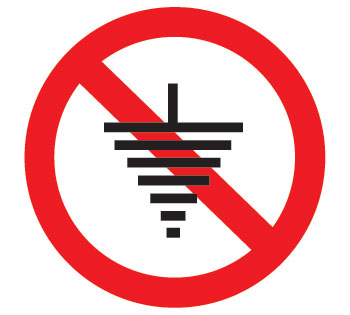
No grounding
To some extent, most electrical systems in the developed counties use a system of equipment-grounding conductors, called protective earth (PE) in Europe, to provide an outer layer of defense against electrical shocks from exposed conductive surfaces that could become energized. Of course, as in the U. S., double-insulated appliances and tools can be found that do not require an equipment-grounding system.
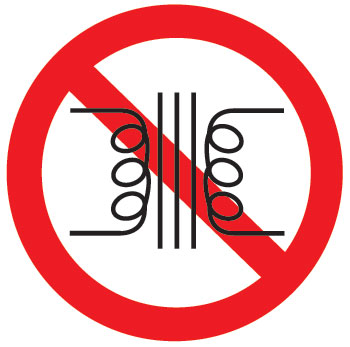
No transformers
There will be no attempt in this article to further the ages-old debate of the safety of ungrounded vs. grounded electrical systems. Given the history, equipment, training, and experiences on both sides of the issue, it appears that either system can provide equal levels of safety. As the world grows smaller, IEC standards in Europe are being harmonized with the standards developed by Underwriters Laboratories (UL) here in the U. S. and the codes are slowly adopting similar requirements and allowances.
Impact on PV System Design
Since the U. S. uses grounded electrical systems, PV systems installed in the U. S. have been required to have a grounded circuit conductor since 1984 when PV requirements first appeared in theNational Electrical Code (NEC).From the beginning, PV systems with a maximum systems voltage of 50 volts or below have not required a grounded circuit conductor and inNEC–2005, Section 690.35 was added to theCodeto permit the use of ungrounded PV arrays with few voltage restrictions.
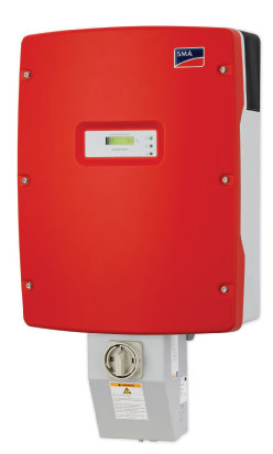
Photo 1. A 9 kW transformerless inverter by SMA Solar Technologies AG
In utility-interactive PV systems, the inverter can be greatly simplified to a conceptual switching device and a filter with other added control components. Of course, how the utility-interactive inverter actually works is far more complex. The switch reverses the polarity of the dc output from the PV array 120 times per second to generate a 60 Hz waveform that is shaped into a sine wave by the filter. In Europe, they use 100 switches per second to get 50 Hz. Because the European PV arrays and the electrical system are ungrounded, the PV utility-interactive inverter can be relatively simple compared to what is required in the United States. In the U. S., with a grounded circuit conductor from the PV array and a grounded circuit conductor in the ac inverter output circuit, it is not possible to use a direct switching device because the switch would be shorted as it tried to reverse the polarity of the dc circuit into an ac signal. A transformer is required in inverters used in the U. S. to isolate the grounded dc circuits from the grounded ac circuits. The transformer is usually a heavy, costly, and bulky device that decreases efficiency, increases the size, and increases the shipping costs of the inverter.
U. S. inverter manufacturers and inverter manufacturers in the rest of the world can now sell transformerless inverters in the U. S. Those inverters must be used with an ungrounded PV array, and theNECallows such ungrounded PV arrays (see 690.35). Several inverters are on the market now (see photos 1, 2, and 3). What are these systems going to look like to the PV installer and the inspector?
The Ungrounded PV System
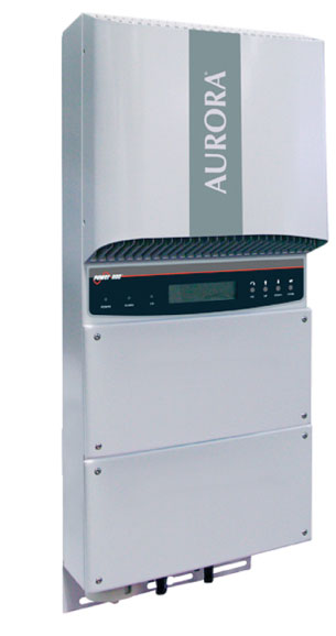
Photo 2. A 5 kW transformerless inverter by Power One
These ungrounded systems are not going to be significantly different from the PV systems that we have been installing and inspecting for many years. They will continue to have a system of equipment-grounding conductors that will connect the module frames, racks, enclosures of combiners, disconnects and inverters together and to ground (earth in Euro-speak).
According to NEC 690.35(B), dc overcurrent protection (when required for three strings of modules or more) will be required in both of the now-ungrounded circuit conductors. PV source circuit combiners for multiple strings of modules will have overcurrent protection in both the positive and negative dc inputs from each string of modules.
The PV dc disconnecting means will be required in both of the ungrounded conductors [690.35(A)]. With disconnects required in each ungrounded circuit conductor, external and internal disconnects will have a switch pole in each of the conductors coming from the PV array.
Ampacity calculations will be the same for grounded and ungrounded systems, and the calculations for maximum system voltage will be the same.
The color code of white for a grounded conductorwill no longer be used; and it is logical that the color code of red for a positive conductor and black for a negative conductor be used, but there is noCoderequirement that these colors be used. As before, the module interconnecting cable and other short-runs of exposed single conductor cables will usually have black insulation (for superior UV resistance) with colored markings used for identification. As an exercise, look at photo 4 and determine what sort of system is shown.
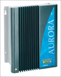
Photo 3. A 3.6 kW transformerless inverter by Power One
All exposed single-conductor cables including those attached directly to the module must be the new PV Wire or PV Cable made and listed to UL Standard 4703 [690.35(D)(3)]. Installers and inspectors should be aware that some of the European PV Cables, PV Wires or other cables with similar names made for the European market (and even made to UL Standard 4703) may use fine-stranded, flexible conductors and it will be difficult to obtain lugs and terminals suitable for use with these cables where they transition to a conduit wiring method. (See NEC 690. 31(F) and “Perspectives on PV” in the January/February 2005, IAEI News).
The inverter must be listed and clearly marked for use with ungrounded PV arrays, and it must have an appropriate internal ground-fault detection and indication system [690.35(C)]. That circuit will not be required to interrupt the ground-fault current (as is required on grounded PV arrays) because on the first ground fault on an ungrounded system, there will be no ground-fault currents. The inverter or charge controller will be required to shut down and indicate that a ground fault has occurred.
Summary
Ungrounded PV arrays, permitted by theNEC, will allow the use of the new transformerless inverters. Color codes will no longer require the white conductor. Disconnects will have poles in both the negative and positive conductors; and overcurrent devices, where required, will be in both conductors too.
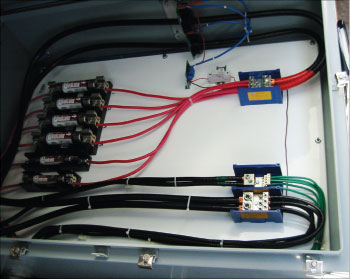
Photo 4. Is it an ungrounded PV source circuit or an improperly color-coded grounded source circuit?
For Additional Information
If this article has raised questions, do not hesitate to contact the author by phone or e-mail. E-mail: jwiles@nmsu.edu Phone: 575-646-6105
See the web site below for a schedule of presentations on PV and theCode.
A color copy of the latest version (1.91) of the 150-page,Photovoltaic Power Systems and the 2005 National Electrical Code: Suggested Practices, written by the author, may be downloaded from this web site:http://www.nmsu.edu/~tdi/Photovoltaics/Codes-Stds/Codes-Stds.html
The Southwest Technology Development Institute web site maintains a PV Systems Inspector/Installer Checklist and all copies of the previous “Perspectives on PV” articles for easy downloading. Copies of “Code Corner” written by the author and published inHome Power Magazineover the last 10 years are also available on this web site:http://www.nmsu.edu/~tdi/Photovoltaics/Codes-Stds/Codes-Stds.html
The author makes 6–8 hour presentations on “PV Systems and theNEC” to groups of 60 or more inspectors, electricians, electrical contractors, and PV professionals for a very nominal cost on an as-requested basis. A schedule of future presentations can be found on the IEE/SWTDI web site.
An Update on Microinverters and AC PV Modules
As the microinverters, combinations of microinverters attached to PV modules, and the AC PV modules come to market, there will be and already has been some confusion about the code requirements for various products.
Both microinverters and microinverters attached to PV modules in the field or in the factory that have any exposed dc single conductor cables are required to meet all of the dc wiring requirements in theNEC. These may include 690.5 ground-fault detector requirements, dc and ac disconnect requirements (potentially handled by connectors listed as disconnects), and inverter dc grounding electrode requirements. Confusion arises when these are calledAC modules. They are not AC PV modules.
TrueAC PV modules, as defined inNEC690.2 and 690.6, have a module and inverter assembled as one environmentally protected unit in the factory, and there is no accessible dc wiring. None of the dc wiring requirements in theCodeapplies, because there is no dc wiring outside the listed unit. A single equipment-grounding connection will usually be the only requirement to properly ground the combined module/inverter assembly.


Find Us on Socials