As climate change continues to impact our daily lives with increasing average temperatures and more numerous severe weather events, we can expect that the existing and aging utility transmission and distribution system will continue to be affected by local and regional blackouts and brownouts. Those severe weather events can and have included heavy snowstorms, temperatures exceeding record lows, raging forest fires, high winds in localized thunderstorms, and significant lightning activity, all of which can damage utility electrical systems and all sizes of photovoltaic (PV) power systems. In many cases, such damage and the resulting interruption in service are unavoidable. However, while the electrical utility service providers should and usually have addressed these issues on their systems, some do not. Some actions can make the residential, commercial, and even larger PV systems more resilient and robust under the impending threat of more frequent severe weather.
The Basics
Some of the actions described below are best implemented during the design and installation of the PV system. Others can be implemented on existing systems. Inspectors should make a note of systems that they inspect that have some or many of these features because it will provide some indication that the installer or designer is providing a quality system with as much protection for the owner from system damages and loss of system output as possible. Some of the sections are considered optional or permissive under the requirements of the National Electrical Code (NEC), and some would be considered above or more robust than Code requirements. Some of these actions are based on solid engineering principles. Others are based on activities that have resulted in enhanced system performance or robustness over time without complete engineering substantiation.
Costs. Unfortunately, in this highly competitive marketplace of PV system installations, there are continuing efforts to drive the installed and lifetime costs to an absolute minimum. This includes major grants and contracts from the US Department of Energy to come up with new and unique ways to design and install PV systems that can lower the cost. There are continuing efforts to streamline the inspection process, which will assist in lowering the installed cost of PV systems. And the technologists are developing new PV module materials and new inverter technologies that can reduce equipment costs. New racking systems are assisting in reducing labor costs and speeding installations.
But to address the various actions that can be taken to reduce the impact of severe weather events on PV installations, costs must be increased because additional equipment and installation time may be required. History will be the judge of whether these actions are cost-effective or not. People owning residential and commercial PV systems that provide power for their home or facility when other nearby homes and buildings do not have power will probably judge the additional costs worthwhile. Utility-scale systems may also benefit from additional protective measures. Owners of PV systems that have been damaged due to severe weather may wish that those upfront or retrofit investments had been made on their systems.
Thunderstorms. Thunderstorms produce lightning, high winds, heavy rains, and in some cases, hail. System design and installation can deal with each of these to minimize the impact of these severe weather events. Direct lightning hits to the PV array will produce the most damage to the electrical systems, but the damage can be minimized by careful design and installation. High winds can result in PV modules and racking systems being physically torn from the buildings. Again, appropriate attention to careful design and installation can minimize the impact of these severe weather events. While equipment that is to be mounted outdoors is generally designed to resist heavy rains, that equipment must be properly mounted.
Extreme Temperatures. Increasing average temperatures are going to be with us for the foreseeable future, with the exception of unusual weather events which can result in exceptionally low temperatures. High temperatures stress equipment like inverters and temperature-sensitive overcurrent devices like fuses and circuit breakers. These devices and equipment should be mounted in locations where they are not heated by direct sunlight exposure.
On the other hand, very cold temperatures that are below the expected low temperature (NEC 690.7) design point for the PV system may result in inverter and/or charge controller damage in certain circumstances.
Looking Deeper
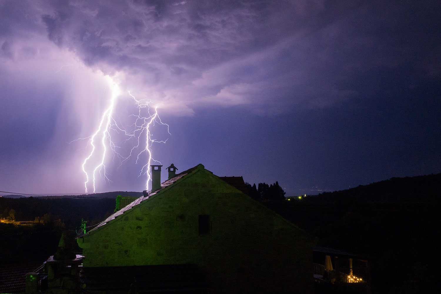
High Winds. Building codes deal with sustained high winds over a given region with some consideration to the frequency of higher sustained winds in repeated storms (like hurricanes). However, the winds associated with extreme weather events like tornadoes and severe thunderstorms are not directly addressed. PV arrays and their large modules represent significant amounts of areas that are subjected to the high winds during thunderstorms which can approach or exceed 60 to 70 mph. When impacted by high winds, these large surfaces generate significant up forces and down forces on the mounting structure that holds the PV racking system to the roof. Unconventional PV array mounting systems on the roof of dwellings should be avoided, particularly in high wind areas (see photo 1).
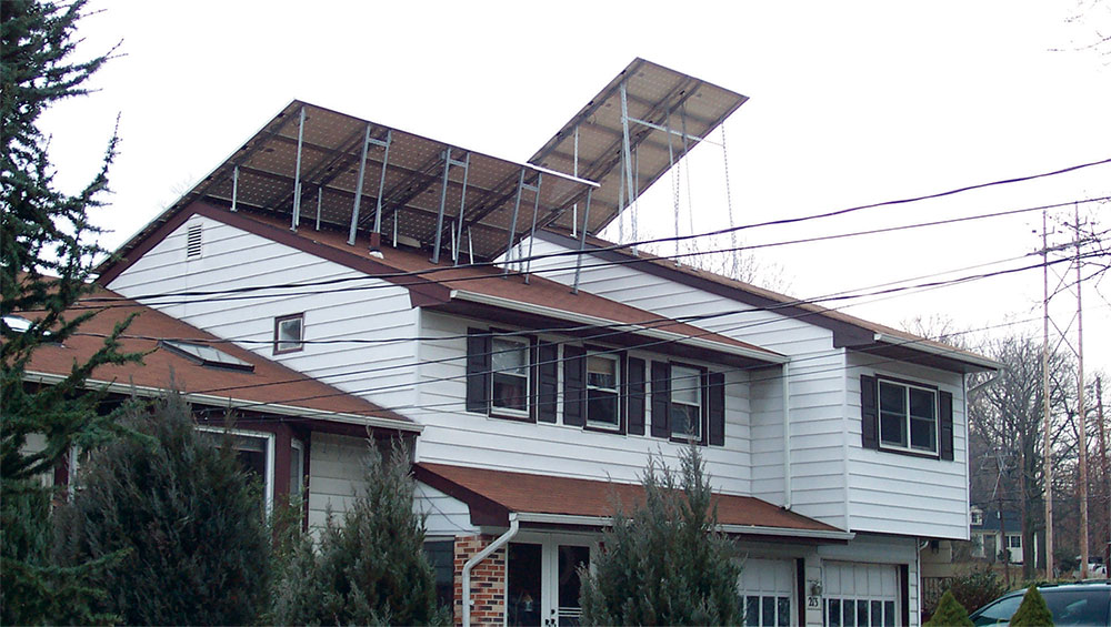
Residential construction is a very competitive business. The builders, including the framing subcontractors, will generally use the minimum of materials necessary to meet the local codes or the local inspection requirements. It can be expected that severe local thunderstorms may continue to increase as average temperatures increase due to climate change. Roofing practice, depending on location, may result in the use of ½ inch or 7/16-inch OSB sheathing for residential roofing decking. Trusses supporting the roof decking may be made with lumber as small as two by fours (2”x 4”). See photo 2. If careful attention is not paid to firmly attaching the PV racking system directly to the trusses underneath the decking, there is a possibility that high winds may cause the rack and the PV array to become detached from the roof and damage not only the PV array but the roof in the process. If the racking system mounts are not directly screwed into the roof trusses and only attached to the OSB decking, then there is a possibility that the racking mounts and attachment lag screws will not be able to resist the high-wind forces during severe thunderstorms.

For similar reasons on commercial buildings and on ground mount PV arrays, an additional safety factor should be designed into the attachment points and methods used to secure the PV racking system to the structure or to the earth. This may be somewhat difficult to achieve on ballasted roof mounts where there are no roof penetrations since increasing the weight of the ballasts may stress the roof with too much weight. Structural engineers should be involved.
Lightning Protection-Early Prevention. PV arrays with their grounded, metal-framed modules are typically mounted in locations where they have full exposure to the sun, hopefully from sunrise to sunset, with no surrounding tall structures. This makes them look somewhat like lightning rods. The Code-required grounding of the metal module frames and the racking structure will help to minimize the damage caused by nearby lightning strikes. And in fact, sometimes, depending on the quality of the connection to earth, even a direct lightning strike may cause little or no damage. However, in general, nearby indirect or direct lightning strikes can and have caused damage to the modules, DC combiners, and the connected inverters or charge controllers.
Such damage can be minimized by rigorously following the NEC requirements for bonding and grounding throughout the system (690.43, 690.45, 690.47). If the next larger size of the required bonding or grounding conductors is used, the resistance to the high current flows from lightning strikes or induced currents due to nearby lightning strikes will be minimized, and any damage may be minimized. The better the connection to earth, the more likely that any high currents from lightning strikes will be directed to ground/earth and not through the PV system equipment. Special attention should be given to Section 690.47(B).
This section allows the installation of optional, additional grounding electrode conductors and grounding electrodes in the PV system as allowed by 250.52 and 250.54. For rooftop-mounted PV arrays, it is usually a good idea to install one or more of these additional grounding electrode conductors directly from the PV array racking and/or module frames to a grounding electrode that is located as closely as possible to the PV array. This grounding system is in addition to any other PV system or premises grounding electrode system and is not required to be bonded to any other grounding electrode. A direct path from the PV racking structure and/or the module frames to earth allows induced lightning currents or currents from direct lightning hits to be routed directly to earth without (or at least minimizing) the flow of currents through the required lengthy equipment grounding conductors down from the PV array through any combiners, the inverter or charge controller and then to the existing premises grounding electrode.
For ground-mounted arrays, the metal support structures installed in the ground serve as additional grounding electrodes even though they may not be the required 10 feet in the soil. Of course, an insertion depth of 10 feet or more provides additional structural rigidity (to deal with high wind loading) as well as meeting the NEC requirements for grounding electrodes. The installation should ensure that the racking system (listed to Underwriters Laboratories Standard UL 2703) is electrically bonded to these metal support structures and that any rotating parts for trackers be fully bonded together.
Due to high solar radiance in the southwestern United States, numerous residential, commercial, and utility-scale, ground-mounted PV systems are installed in this region. Unfortunately, the soils in these regions are usually dry and not very conductive, making it difficult to get a good connection to the earth. Multiple 8-foot or longer grounding electrodes should be installed and bonded together as permitted and/or required by the NEC or local codes. Chemical grounding rods which absorb moisture from the air and increase soil conductivity might be considered. Where construction is associated with the PV system installation and reinforced concrete is being used, concrete encased electrodes should be added to the system of driven grounding electrodes. The more durable metal surfaces that can be buried 30 inches or more in the ground and used as part of a grounding electrode system, the better (250.53).
Anyone who has traveled extensively through the major airports in the United States will notice that most airport buildings and aerial tramways are equipped with a large number of lightning rods. While there are codes (NFPA 780) dealing with the installation of lightning rods and lightning arresters, some large, remote, standalone PV systems at National Parks have used a system of “lightning rods” (metal pipes) attached to the north side of the PV array racking system. These “lightning rods” extend 10 to 15 feet above the highest point of the PV array, do not shade the array, and are located close enough together to provide some degree of protection from direct lightning strikes to the PV array structure. In other areas, very high wooden telephone poles have been installed on each side of the PV array with a grounded conductor stretched between each pair that is 20 to 30 feet above the PV array. These grounded conductors serve to protect the PV array located below it from direct lightning strikes in a similar manner to the grounded conductor found at the top of utility transmission towers and lines.
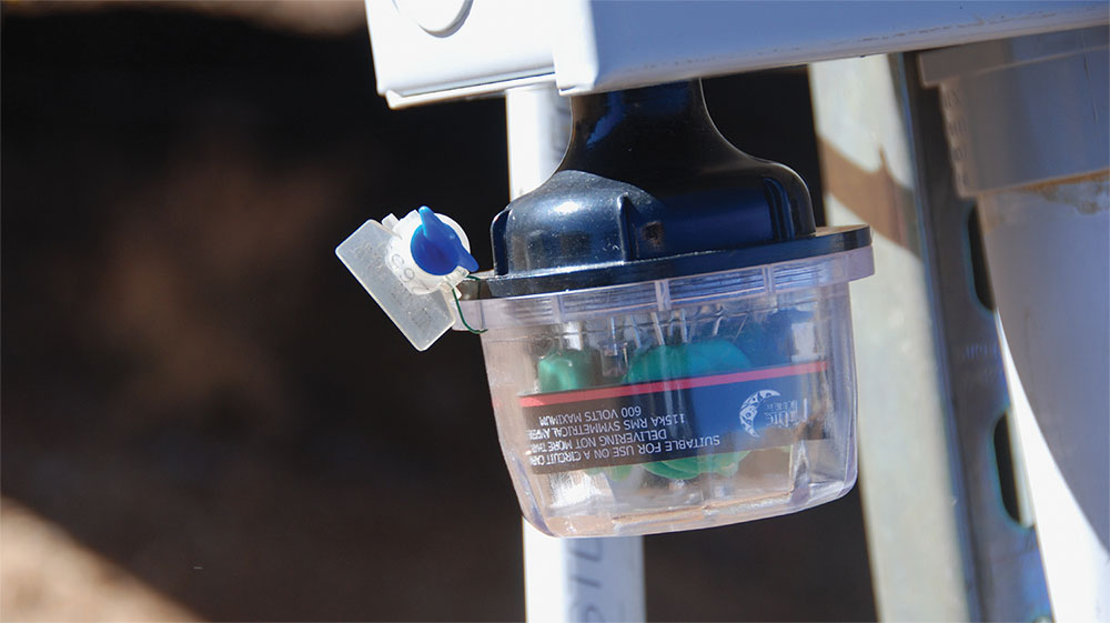
Lightning Protection At The Equipment. In severe thunder-storms, nearby lightning strikes may induce high surge currents and the resulting high surge voltages in the conductors to the PV system, including the conductors from the PV array and the conductors from the utility. Inverter and charge controller manufacturers and DC combiner manufacturers make their products as robust as possible given cost constraints. Given that fact, it may be a wise investment to increase the overall system protection with added equipment. A number of companies make surge-protective devices that can be used on the DC circuits and the AC circuits at the inputs and outputs of electronic equipment (see photo 3). Article 242 in the NEC describes overvoltage protection, including the various types of surge protective devices (SPDs). The correct device (AC or DC) and the voltage rating must be selected for each application. When properly selected and installed, these devices should minimize any equipment damage that would result from the remaining high surge currents and voltages that have not been fully diverted to ground by a high-quality grounding system.
For higher degrees of protection from lightning-induced surges, all incoming electrical circuits to a dwelling or other facility should have surge protection. Such circuits would include data lines from the PV system, telephone lines, TV/Internet/antenna cables, and any other electrical circuit to or from the building.
Extreme Temperatures – The Hot Side. Most PV Equipment Is tested, evaluated, certified, and listed for operation at a maximum ambient temperature of 40°C. If equipment like inverters, charge controllers, DC combiners, and the like are installed in locations where sunlight can provide additional heating, these devices may be affected in two ways. Most of the electronic products will control and limit their internal temperatures to a point that will prevent immediate damage. They do this by reducing the power output, which reduces internal heating. When ambient temperatures exceed 40°C (104°F), an inverter’s power output may be significantly reduced. Furthermore, operating the inverter in this high-temperature region for extended periods of time may result in a shortened lifetime since internal components like electrolytic capacitors are subject to faster aging due to the higher temperatures.
These PV temperature-sensitive devices and equipment should not be mounted where they are exposed to direct sunlight. They should preferably be in controlled temperature environments [i.e., inside a conditioned building or at least a building that gets no hotter than a temperature of 40°C (104°F)].
Overcurrent devices listed for PV applications (fuses and circuit breakers) are evaluated at a maximum temperature of 50°C (122°F). Where overcurrent devices such as those in DC combiners or those mounted in cable-type fuse holders are exposed to direct sunlight in hot climates (and they are getting hotter) with ambient temperatures above 40° C, the overcurrent devices themselves may be exposed to operating temperatures in excess of 50° C. This is a violation of the listing on the overcurrent device [110.3(B)] and may result in nuisance tripping/blowing. It is not recommended that any equipment containing an overcurrent device be mounted in a location exposed to direct sunlight and, in particular, not mounted near a surface like a roof or an array structural member that may increase the local ambient temperature.
Extreme Temperatures – The Cold Side. Electronic equipment such as inverters and charge controllers used in PV systems are listed for a minimum ambient temperature of -40°C (-40°F). When equipment is operated at temperatures lower than this, start-up conditions for the internal electronics (particularly electrolytic capacitors) may not be optimal, and failures may occur. Even here in the United States, there are some locations where winter temperatures drop below -40°C (-40°F). It would not be a good idea to mount electronic equipment in outdoor locations in these environments. The equipment had best be located in indoor locations that are at least partially conditioned to keep the temperatures above -40°C.
The NEC (690.7) requires that an expected low temperature for the installation location be selected and used in the calculation for the increased voltages available from the PV array as the temperatures decrease. Many installers use published historical records showing average, minimum, and maximum ambient temperatures to select an expected low temperature for calculating the voltage rating of modules connected in series strings. With continual increases in the average temperature in most parts of the country, the low temperatures in these historical records will continue to be increasing. However, unexpected severe cold weather occurrences are not uncommon, as witnessed a few months ago in Texas and other parts of the southwestern US.
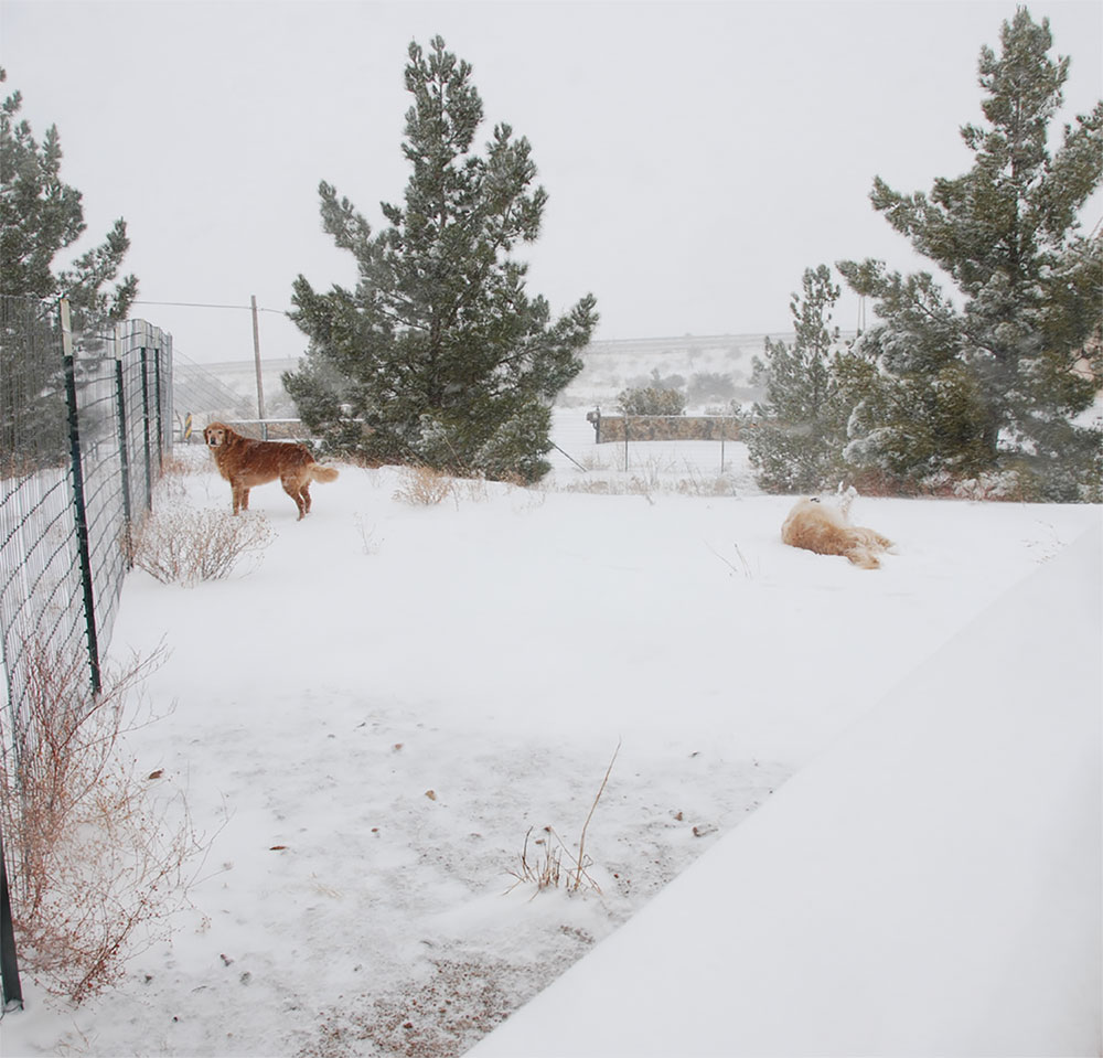
As an example, in my location (southern New Mexico), an expected low temperature of 14°F (-10°C)‚ is used in voltage calculations to determine the number of series-connected PV modules that can be placed in a string without exceeding the maximum input voltage of the inverter. A few years ago, the thousands of PV systems installed in the area using this calculation were then exposed to several days of a record low temperature of -2°F (-19°C) [see photo 4]. And like the utilities in Texas recently, the local utilities were not prepared for these low temperatures. Electrical power blackouts and rolling blackouts were instituted along with natural gas delivery curtailments. We were quite fortunate in that the rolling blackouts did not occur until late in the afternoon when the PV arrays had time to heat up to significantly warmer temperatures than the overnight cold-soaked temperatures of -2°F(-19°C). If those blackouts had occurred in the early morning when the arrays were cold-soaked with little, if any, solar heating, it has been estimated that many PV inverters would have been subjected to excessive DC input voltages and damaged as the utility blackouts switched the inverters on and off exposing them to very high cold-temperature open-circuit DC PV voltages. With the sun-heated arrays, the interrupted voltages for them were within the inverter specifications.
The only truly effective way to deal with this situation is to reduce the number of modules in series so that the string voltage under very cold (unexpected/abnormal) temperatures will not exceed the maximum inverter input voltage rating. Of course, this reduces PV array power output, but that can be compensated for by adding additional strings of PV modules to the PV array. And the resulting hot-weather string voltages due to the reduced numbers of modules connected in series must be sufficient to start the inverter when temperatures are much hotter. Another method, if rolling blackouts are predicted during cold weather, is to physically disconnect the PV array from the inverter (open the DC PV disconnect) during the early morning hours until the PV array is warmed by the sun. This latter method may not be practical for the typical unqualified homeowner.
Rain. Most PV inverters have enclosures that are rated NEMA 3R, which indicates that they will resist a degree of wind-blown rain. The same inverters also have ventilation louvers and drainage holes in the bottom of the enclosures. These are also designed to allow for proper temperature control, resist blowing rain, and allow any internal condensation to escape. However, the NEMA 3R designation is associated with a specific range of mounting positions.
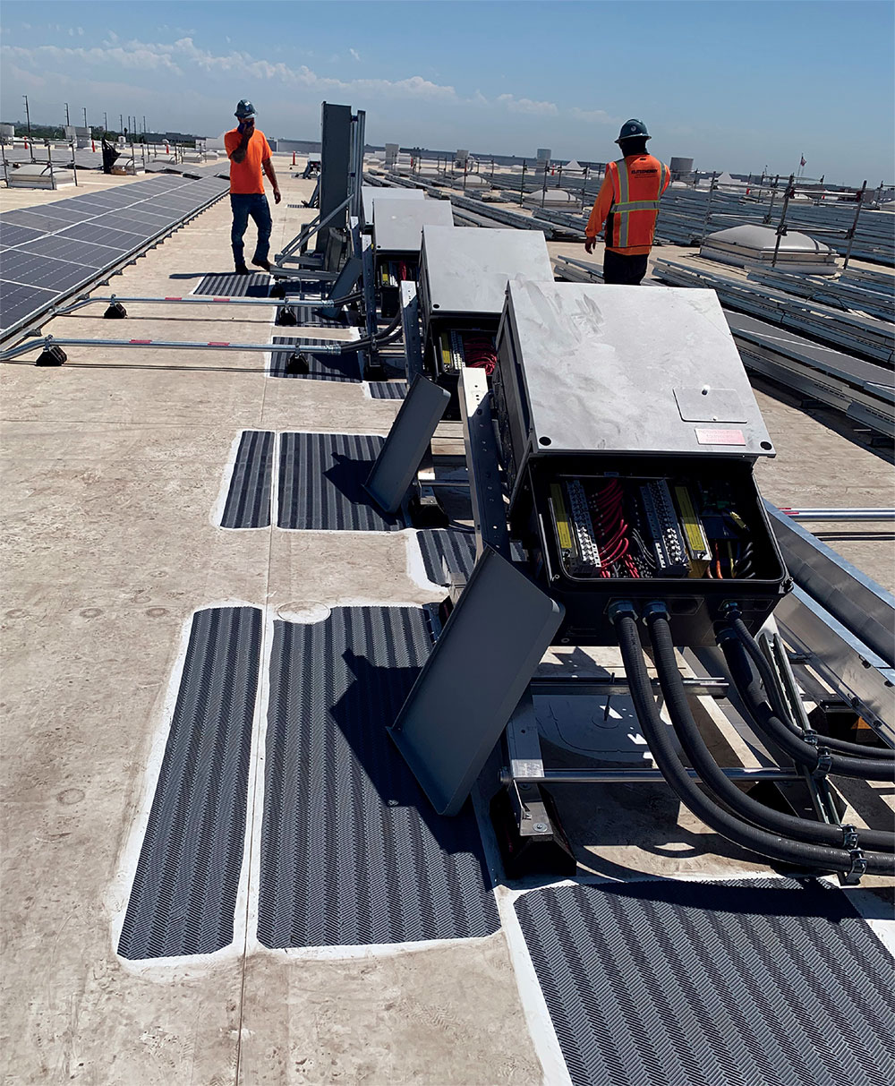
In some cases, there must be a solid surface (wall) behind the inverter, and in other cases, the inverter may be mounted on open structural supports. But in either situation, the inverter must be oriented within a certain degree of vertical. If this restriction on the orientation of the inverter is not followed, the NEMA 3R designation is invalidated, and the inverter probably is being mounted in an orientation that violates the instructions found in the installation manual and, therefore, the listing (see photo 5). The requirements for mounting the inverter (both in indoor and outdoor locations) should always be followed for maximum resilience, durability, and longevity.
Snow. Accumulations of snow on the PV array can reduce the output from just slightly for light snow (a quarter of an inch or less) to zero under heavy snow. Where the PV array is accessible (ground-mounted or roof-mounted via long-handled brooms), the snow can be removed before it goes through a freeze-thaw cycle which would then make it more difficult to remove. Soft fluffy snow can be removed with a leaf blower in some cases. Water, even cold water, probably should not be used to remove snow due to the possibility of mineral buildup on the modules or unequal temperatures between the water and the cold module glass damaging the modules.
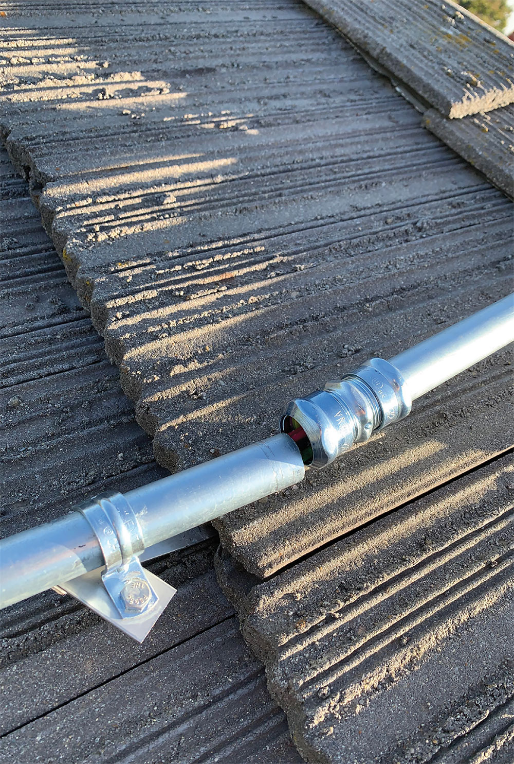
Very high and very low temperatures (over time) can cause excessive expansion and contraction of installed conduits that can result in conductor damage where the conduits are pulled loose from their fittings. Proper use of expansion fittings should minimize this issue (see photo 6).
The Ultimate Solution – At a Cost. A utility-interactive PV system with an energy storage (battery) backup system can provide 24/7 power to a dwelling or commercial facility in the event that utility power is out for a number of days. Such a backup system, depending on the needed number of days of operation without sunlight, is not inexpensive. For example, if a utility-interactive PV system is sized to offset the average daily energy use of a dwelling or commercial building, adding an energy storage backup system that could operate for three days without sunlight (cloudy weather) might double the cost of the initial PV installation. After the installation of a utility-interactive PV system, an energy storage backup system might be added at a later date. An evaluation of the reliability of the local utility coupled with an assessment of the historical and predicted weather conditions and the cost of such a system should be used in making the decision to add energy storage backup to a new or existing utility-interactive PV system.
Summary
Increasing average temperatures coupled with unpredictable severe weather events, including localized thunderstorms with high winds, lightning, and heavy rains plus out-of-control forest fires (exacerbated by high temperatures, less precipitation, and high winds) along with other unanticipated events will be with us for the foreseeable future. Planning for these events now and implementing protective measures to deal with them can reduce their impact on the performance of not only utility power systems but the PV systems that supply electric power to homes, businesses, and industry.