Some in the electrical industry hold two beliefs about copper-clad aluminum (CCA) conductors when used in power circuit applications. One of these beliefs is that conductors of CCA are just like single metal aluminum conductors and should therefore be treated in the same manner. The other belief is that at 60 Hz, the current in CCA conductors runs mainly in the copper layer, like a “skin effect,” rather than being distributed throughout the entire cross-section of the conductor. This white paper provides evidence that these beliefs are unfounded.
ORIGINS OF THE MISUNDERSTANDING
Many in the electrical trade, including some in the regulatory community, believe that CCA conductors perform the same as aluminum conductors. This perceived equivalency may come from not recognizing that CCA is a bimetal, different than the two metals used to manufacture it.
Another source for misunderstanding may come from assumptions based on the structure of the National Electrical Code® (NEC®), which could do a better job differentiating the allowed conductor materials. Regardless, the evidence shows that CCA conductors perform uniquely from those made with aluminum. For baseline purposes, this white paper also provides testing data with copper conductors of equivalent ampacity. The following are a few points that demonstrate that CCA and aluminum as conductor materials are not the same and should be handled differently. These facts are easily verified using common electrical testing equipment and following industry-adopted standard procedures.
FOLLOWING THE DATA
Comparing the Performance of CCA and Aluminum Conductors
A fundamental concept of small branch circuit conductor sizes, such as 14 – 10 AWG, including those constructed with CCA, is that AC current density is, in fact, more evenly distributed throughout the cross-section of the conductor than one might think.
This is because the skin effect, i.e., the tendency of AC current to concentrate at the outside of conductors, is negligible at 60 Hz in these sizes of conductors, as the conductor diameter is small compared to the “skin depth,” a metric describing the distance over which the skin effect takes place. This contrasts with very large conductors, such as 350 kcmil and larger, where the diameter is large enough to exhibit a pronounced uneven distribution of current, or with conductors used for data transmission or operating at radio frequencies, where the skin depth is much smaller due to the high-frequency signals.
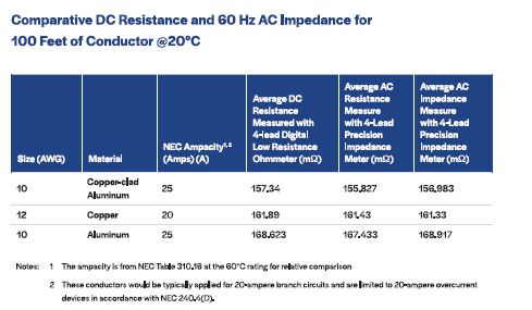
The negligible skin effect in building wire at 60 Hz can be demonstrated when one compares the differences between the conductor’s DC resistance and its AC impedance. This white paper compares samples of 10 AWG solid aluminum conductors to 10 AWG solid CCA conductors. This size CCA or aluminum conductor would be applicable for a 20-ampere branch circuit in accordance with the NEC®.
All the testing described below was completed on three samples of each conductor material. The results reported here are the averages of those three measurements. The resistance testing was completed using a calibrated Megger Digital Low Resistance Ohmmeter (DLRO). The DC resistance test results of conductors of the same length (for this case, 100 feet) and size (10 AWG) at a current of 10 amps found the measured DC resistance of CCA to be, on average, approximately 11.28 mΩ or 6.69% lower than aluminum, see Table 1. It is logical that CCA has a lower DC resistance since 27% of the CCA’s mass is copper — more copper, lower overall resistance.
Impedance measurements for the 100 feet of conductor were completed using a calibrated Keysight E4980A LCR meter and validated with a Keysight E4990A Impedance Analyzer. The test results at 60 Hz, found the difference for the resistance part of the impedance between 10 AWG CCA and 10 AWG aluminum of equal lengths is, on average 11.60 mΩ or 6.93% less for CCA. In that the copper of CCA is highly concentrated at the periphery of the conductor, if current were to be most dense at the skin, then CCA should have much less impedance than aluminum. These results demonstrate that it does not. As shown in the data, Table 1, the difference between the DC test at 11.28 mΩ and the AC test at 11.60 mΩ shows almost identical results.
The testing results for the same wire samples comparing the total AC impedance at 60 Hz for 10 AWG CCA to 10 AWG aluminum indicate a difference of 11.93 mΩ or 7.06% less for CCA.
As shown in Table 1, comparing the average DC resistance and the average 60 Hz AC impedance for CCA, they are essentially equal. If AC current at 60 Hz were to be heavily concentrated (denser) at the periphery of a conductor, as many incorrectly believe, the percentage difference for the AC impedance of CCA would be significantly higher than that found when comparing CCA to CCA or CCA to aluminum. Ten percent of CCA’s cross-sectional area is highly conductive copper, all of which is located at the periphery of the wire in a thick band where the AC current is presumed to be the densest. The conclusion from the above data indicates that AC current at 60 Hz is more evenly distributed throughout the entire cross-section of the conductor than conventional wisdom has led many to believe.
The DC Resistance/AC Impedance of CCA and Aluminum Are Not the Same
In gaining the above insights into the current density in small conductors for AC circuits at 60 Hertz, another important fact has been uncovered. Even though the NEC treats CCA and aluminum as being the same, CCA is a more electrically efficient conductor than aluminum size for size. When comparing CCA and aluminum of the same diameter and length, CCA measures both a lower DC resistance and lower AC impedance. Below is a comparison based on averages of multiple sets of readings and samples:
CCA Compared to Copper Conductors
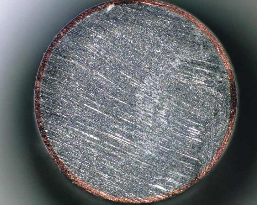
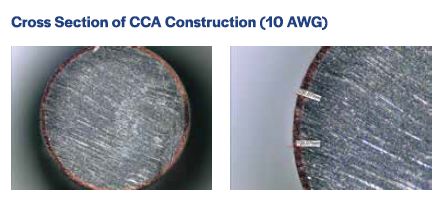
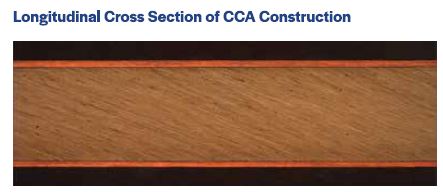
As shown in the cross-section images in Figures 1 and 2 below, the construction of CCA has an area comprised of a maximum 90% aluminum center with a minimum 10% copper outer layer that is metallurgically bonded to the aluminum center. This equates to 27% mass for copper and 73% mass for aluminum. For equivalency’s sake, applications in the NEC require CCA to be increased by two AWG sizes in relation to copper, such as 12 AWG copper to 10 AWG CCA, reference NEC Table 310.16.
From the testing conducted for this white paper, it should also be noted that when compared to copper conductors of two AWG sizes smaller, CCA was found to have a lower DC resistance and AC impedance, see Table 1. This has important implications for equivalency in performance. Generally, lower resistance in one conductor over another equates to lower heat generation from the wire and helps to reduce heat generation at termination points. In an overcurrent condition, a lower total conductor and connector contact resistance can make all the difference between a conductor or connection overheating or not overheating. As discussed below, the total resistance for CCA in splices is close to that of copper and significantly less than aluminum.
The Performance of Conductors in Electrical Connections
DC Resistance of CCA and Aluminum at Splice Points
In addition to the above discussion on the conductor itself, more insightful data can be acquired about CCA when measuring the resistance of connector assemblies, such as wire splicing connectors. The resistance of CCA in splicing connectors compared to aluminum and copper is a case in point. Understanding the resistance at splice points is important because the resistance of the assembly can be equated to electrical efficiency and heat generation at the splicing connector.
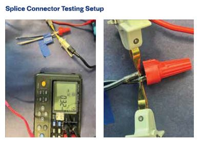
Again, test results comparing splices of 10 AWG CCA to both 10 AWG aluminum and 12 AWG copper under equivalent test conditions found a significant difference in the resistance between the assembly for CCA and aluminum conductors. All the connections were of the same conductor material, CCA to CCA, copper to copper, and aluminum to aluminum. See Figure 4 for a graphical representation of the test setup and Tables 2, 3, and 4 for the test data.
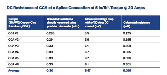
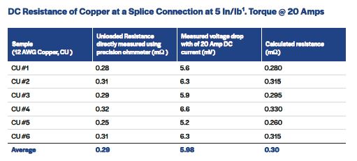
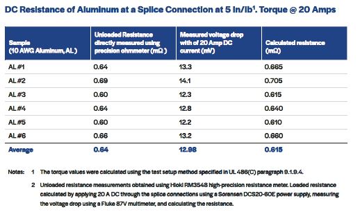
The average DC resistance for splices with 10 AWG CCA is approximately half that for splices using 10 AWG aluminum and effectively equivalent to 12 AWG copper. As shown in the photos below, Figure 3, the assembly of copper, CCA, or aluminum conductors in a wire splicing device was measured with a precision 4-point resistance measuring meter. These measurements were taken at a location just outside the splice connector to minimize the resistance measurement contribution of the bulk conductors. To validate the measured resistance results, separate tests were completed at the typical rated current by injecting 20 amps DC from a regulated power supply into the circuit and measuring the voltage drop.
The above information is important to understand for designers, installers, and electrical inspectors. Based on the testing, properly installed splicing connectors found CCA to be effectively equivalent to copper and twice as efficient as aluminum.
The primary reason for the poorer performance of aluminum is the existence of an insulating surface oxide layer inherent to that metal. Aluminum oxide is a poor electrical conductor and forms in milliseconds on the surface of aluminum when exposed to open air. Therefore, for current to pass through a splice made with aluminum wire, the surface oxide layer must be cracked and not allowed to reform. Only then can the current flow, and it only flows through the penetrations.
On the other hand, CCA has no aluminum oxide layer, and the interface of CCA to the connector or another conductor is copper. During the manufacturing of CCA in an oxygen-free environment, the oxide layer is completely removed from the aluminum surface before being bonded to a thick layer of highly conductive oxygen-free copper through a metallurgical bonding process. The result is a bimetallic conductor with the beneficial properties of both metals. The bimetallic conductor has decreased overall resistance and lighter weight and eliminates the highly resistive aluminum oxide layer where the copper is the material in contact with connectors and other conductors.
Summary
Data and science drive changes to one’s perspective, as well as to the conventional wisdom of an industry. This new evidence about copper-clad aluminum’s performance is being used in the codes and standards development process to drive change and provide clearer guidance to designers, installers, and inspectors on how to regulate installations made with CCA conductors.
The information and testing results provided in this white paper reinforce the following concepts:
- The copper of CCA is primarily employed for electrical connections and terminations, and the current will flow through the entire cross-section of a small circuit conductor.
- The thick copper cladding allows for easy current flow from the conductor at points of electrical connection.
- CCA is not the same as an aluminum conductor.
- For connections, CCA is also not dissimilar to copper metallurgically, both in terms of how it terminates and splices, as well as in terms of how it performs.