Type Metal Clad Cable (MC) is being installed in virtually every type of building under construction today including stadiums, schools, multi-family housing, hotels, commercial retail and office, industrial plants and warehouses along with many other facilities. This article addresses the interlocked armor Type MC cable with conductors No. 8 CU and No. 6 AL and larger for 600 volt installations. Section 334-3 of the National Electrical Code (NEC) (ANSI/NFPA 70 Standard) identifies uses permitted to include services, feeders, branch circuits, wet locations, and certain hazardous locations. Let’s review the installation and inspection aspects of Type MC cable for feeders and services.

Photo 1. Armor cutting tool

Photo 2. MC cable pulled over sheave wheel
MC cable is permitted in sizes 18 AWG through 2000 kcmil for copper, 12 AWG through 2000 kcmil aluminum, or copper-clad aluminum, and employs thermoset or thermoplastic insulated conductors. Installation of MC cable should be in accordance with Article 334 of NEC. The definition in Article 334 identifies Type MC cable as a factory assembly of one or more insulated circuit conductors enclosed in an armor of interlocking metal tape, or smooth or corrugated metallic sheath. The equipment grounding conductor required within a cable with interlocked metal tape sheath may be insulated or bare and may be sectioned. When sectioned, all the sections must be identical. Any additional grounding conductors are required to have green insulation. The sheath of the smooth or corrugated tube Type MC cable or a combination of the sheath and a supplemental bare or unstriped green insulated conductor is suitable for use as the required equipment grounding conductor. The required equipment grounding conductor in conjunction with the cable armor and connector (fitting) serve to satisfy the rule for a low-impedance fault-return path to clear the overcurrent protection device due to a ground fault.
Cable Preparation

Photo 3. Pulling MC cable through floor
Prior to pulling the MC cable, the installer prepares the end by stripping the armor back to expose the conductor. One method of stripping the armor is to cut a ring around the cable with an armored cable cutter being careful to not cut deep enough to damage the insulation on the conductors (see photo 1). Another method is to cut two adjacent ribs of the armor utilizing a rotary cutter and slide the armor off the conductors. Slide a basket grip over the conductor assembly and then tape the basket, conductors and armor together. The pulling force is to be applied to the conductors and not the armor. The installer prepares the route of the cable pull by placing sheave wheels or pulleys at adequate distances to pull the cable without damage (see photo 2). Short distance pulls may not require wheels or pulleys but only smooth surface with which to pull the cable over. Pulling MC cable over hard edges such as angle iron can damage the armor. UL 1569 Metal-Clad Cable testing requirements include a tension test of the armor where a 150 lb. weight is attached to the armor for five minutes. The armor must not separate enough to expose the cable interior. The route of the pull may include many turns, vertical and horizontal distances but always pulls the cable by the conductors and not the armor (see photo 3).
Cable Support

Photo 4. Horizontal support on trapeze
Section 334-10(a) of the NEC requires the cable to be supported and secured at intervals not exceeding 6-ft. (1.83 m). The supports may include strut, trapeze, and rack or cable tray (see photo 4). Generally, the same support systems utilized for metal conduit are used for MC cable except at distances of 6 ft instead of 10 ft as required for conduit installations. The MC cable can be secured by an assortment of clamps used for conduit (see photo 5). Section 334-10(b) Unsupported Cables states, “Type MC cable shall not be required to be supported and secured where the cable is fished, between access points, where concealed in finished buildings or structures and supporting is impracticable.” An example is fishing MC cable down the inside of an existing wall and supporting where accessible.

Photo 5. Vertical MC cable support
Bends in MC Cable
MC cable has no restrictions on the number of bends. The bending requirement for interlocked armor Type MC cable is “seven times the external diameter of the metallic sheath” as stated in Section 334-11(b) of the NEC. If you have a two-inch diameter MC cable the radius of the curve of the inner edge of the bend shall not be less than 14 inches (see photo 6).
Terminating the Conductors
Once the MC cable is supported and secured, the installer will prepare to terminate the conductors. An adequate length MC cable armor should be removed as described earlier, again making sure not to damage the insulation on the conductors, to terminate the conductors. Section 334-12 requires fittings used for connecting Type MC cable to boxes, cabinets, or other equipment shall be listed and identified for such use (see photo 7).
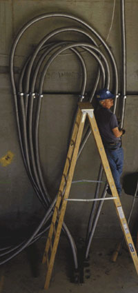
Photo 6. Interlocked armor MC cable bends not less than seven times the cable diameter
The primary function of the fitting is to provide mechanical connection between the cable and the enclosure and ensure that the armor is properly grounded. There should be no sharp edges in the fitting or on the armor which could damage the insulation on the conductors. The installer should square the end of the armor to provide a flush fit with the end stop of the fitting. Selecting the correct size fitting requires the installer to know the dimensions of the MC cable conductor assembly and the armor diameter and the fitting dimensions of the throat opening for the conductors and the clamping range for securing the MC cable armor in the fitting. MC cable has a polyester or paper wrap around the conductor assembly. The fittings listed for MC cable by design may not require an insulating bushing or may have a bushing included in the fitting. The installer should note the instructions with the fitting to determine if a bushing is included with the fitting. The fitting manufacturer may have listed the fitting as usable with Type AC or Type MC cable and thus a bushing is included with the fitting. The bushing in this case may not be required but the installer should verify with the fitting manufacturer if the fitting was listed with or without the bushing for Type MC cable (photo 7).
Parallel Runs
Section 334-23 states, “Type MC cable shall provide an adequate path for equipment grounding as required by Article 250.” MC cable comes with an insulated or bare equipment ground sized provide an adequate fault-current path to protect the

Photo 7. MC cable fitting
conductors in that individual cable. The standard equipment ground supplied for the particular MC cable probably is not sized for multiple runs of cable installed in parallel. In photo 8, ten sets of conductors are required to provide the ampacity for the five circuits. Section 250-122(f) addresses the requirement for properly sizing the equipment ground conductor in each cable run in a parallel. Table 250-122 lists the minimum equipment ground size for the overcurrent device rating. Several years ago, manufacturers started supplying four conductor 750 kcmil aluminum plus equipment ground with a 3/0 AWG aluminum equipment ground as standard stock material instead of the previously supplied 1/0 AWG aluminum equipment ground conductor. The 3/0 AWG aluminum equipment ground enabled the installer to purchase stock 750 kcmil aluminum MC cable and install two standard cables to supply 800 amp equipment. Manufacturers of MC cable will provide cables with larger equipment ground conductors when requested and at least one provides stock sizes covering a range of overcurrent devices (see table 1).
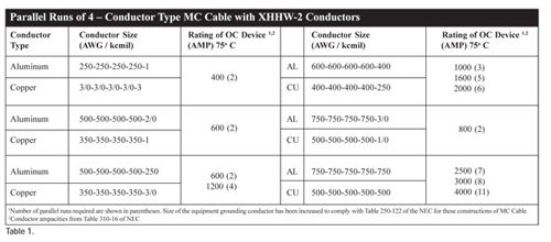
Table 1

Table 2
Vertical Runs

Photo 8. Parallel runs of jacketed MC cable entering gear
For long vertical runs, conductors must be supported to prevent them from being pulled out of their connections by the force of gravity. The conductor insulation must not be subject to damage at bends. Cables installed vertically must not exceed the requirements of Table 300-19(a) even though supported every 6 feet without relieving the gravity and weight of conductors (see table 2). Support is required to prevent the weight of the cable from damaging conductor insulation and to prevent the conductors from being pulled out of equipment terminals. Section 300-19 states, “One cable support shall be provided at the top of the vertical raceway or as close to the top as practical.” One method of supporting and securing multi-conductor armored cables vertically is to install cables with 90-degree offsets with a minimum horizontal distance of two cable diameters. Remember interlocked armor Type MC cable minimum bending radius is seven times the cable diameter. Another method is to terminate the conductors such as in a junction box and start a new section of cable to continue vertically. Note the difference in distances allowed for copper conductors and aluminum conductors, which reaffirms that the supporting requirement is based on weight. In UL 1569, Type MC cable must meet the requirements for tightness of armor on conductors. Cables containing No. 4 AWG or larger conductors must not pull out of a ten foot sample cable suspended vertically for one minute with a 30 lb. weight attached to the conductor more than one-half inch (see photo 9).

Photo 9. Supporting MC cable every six feet
As an inspector, sometimes it is very difficult to identify the conductor type and size after installation. With conduit and conductor installations you must look for cut off pieces of conductor or conductor remaining on reels as a source of information. The same techniques are used with MC cable. MC cable information such as cable and conductor type, size and voltage is shown either on the marker tape included under the armor or on the conductors.

Photo 10. Paying off large size MC cable
Section 334-13 identifies ampacity of MC cable to be in accordance with Section 310-15 or 310-60. Generally the values in Table 310-16 will be applied to MC cable if there are no more than 3 current carrying conductors per cable. Derating is required when there are more than three current carrying conductors per cable. Correction factors apply for ambient temperature above 30ºC (86ºF).
The installation and inspection of electrical components within an electrical system are critical to the performance of the system. As inspectors witnessing installations of Metal-Clad cable, note how the cables are handled, pulling setup, support methods, armor stripping techniques, locations installed, proper bending and correct listed MC cable fitting. This article refers to 1999 NEC but there may be local amendments so always check with the local authority having jurisdiction (see photo 10).