
What could be more important than the protection of life and property? The majority of governing laws, building and fire codes, and standards focus on what is most important: protecting life and property. It’s our job in the industry to understand how the laws, codes, and standards are used in order to accomplish and maintain that protection successfully.
In this article, I will try to focus my attention on specific performance goals of initiating devices used for fire and life safety and why understanding and knowing the devices can improve your awareness when working with fire alarm systems. Keep in mind that initiating devices are only a part of a fire alarm system. In order to maintain full protection of life and property, all aspects of the system should be understood, utilized, and function properly. For this article, I will be focusing on Chapter 17, Initiating Devices, in the 2019 National Fire Alarm and Signaling Code.
Initiating Devices
Initiating devices are used to detect fire, smoke, and emergencies by automatic and manual means, and initiate evacuation, the sequence of operation, and transmit signals for emergency response. The initiating device acts as an input to the fire alarm control panel. Once a signal is transmitted to the fire alarm control panel, the panel creates a response that is programmed into it that will initiate notification devices, building interfaces, and transmit signals for an emergency response. Failure to understand the design, installation, or inspection of initiating devices could lead to devastating results and loss of life and property. It’s our job in the electrical industry to understand the requirements for initiating devices and do our best to ensure that these devices are installed, maintained, and inspected to maintain the integrity of fire and life safety systems.
The National Fire Alarm and Signaling Code specifies the purpose of Chapter 17, Initiating Devices, in Section 17.2.
Automatic and manual initiating devices shall contribute life safety, fire protection, and property conservation by providing reliable means to signal other equipment arranged to monitor the initiating devices and initiate a response to those signals.
Keep in mind that the authority having jurisdiction (AHJ) shall approve any modification or variation to the design in advance and also have the authority to determine if any performance objectives have been met.
Protecting the Integrity
Initiating devices shall be protected and guarded from physical damage. If subjected to physical damage, initiating devices shall have a mechanical guard installed. That guard shall be listed for that specific device so that the performance, operation, or use is not impaired after installation. When designing, installing, or inspecting initiating devices be mindful of the placement and how the environment can be a danger to each and every device.
Since initiating devices are required by Chapter 14 to have Inspection, Testing, and Maintenance done on the devices, they shall be installed in such a manner that provides accessibility for the devices. Sometimes this is easier said than done, especially when governing laws require total coverage per the occupancy type.
At times initiating devices are installed in concealed locations above 10 ft. (3.0 m) above the finished floor or in areas where the detectors supervisory indicator is not accessible to personnel. Section 17.4.6 requires those detectors to have a remote alarm or supervisory indication in a location acceptable by the AHJ. If a remote alarm or supervisory indicator light is provided, the location of the detector and the area it serves shall be at that location that the AHJ approves.
General Requirements for Heat and Smoke Detectors
In accordance with Section 17.5, heat and smoke detectors are not permitted to be recessed mounted. You eliminate the performance of the devices if not installed per the manufacturer’s recommendations and properly. When designing, inspecting, and installing initiating devices, be mindful of wall partitions. Section 17.5.2 specifies that any partition that extends within 15 percent of the ceiling height shall be considered as a separate room.
Governing laws, codes, and standards enforce what type of coverage is needed when installing initiating devices in accordance with Sections 17.5.3. There are three types of coverage: total and complete coverage, partial or selective coverage, and non-required coverage.
- Total coverage requires initiating devices in all rooms, halls, storage areas, basements, attics, lofts, areas above suspended ceilings, and other accessible areas. If there is an inaccessible area that is constructed with or contains combustible materials, that area shall be made accessible, and devices will need to be installed. There are some exceptions to total coverage in Sections 17.5.3.1.1 through 17.5.3.1.5.
- Partial or selective coverage applies only to areas required by governing laws, codes, and standards but do not require every area to be protected.
- In some situations, property owners see value in protecting areas that are non-required. These non-required areas identify installation of initiating devices to achieve specific fire safety objectives.
Heat-Sensing Fire Detectors
A heat detector is an initiating device designed to respond to thermal energy caused by a fire that increases the temperature of a heat-sensing element internal to the detector. The device detects the temperature and initiates a signal if the temperature increases past a specific temperature.
Heat detectors shall be listed in accordance with the applicable standards such as ANSI/UL 521, Standard for Heat Detectors for Fire Protective Signaling Systems in accordance with Section 17.6.1.4. Spot-type heat detectors must include the manufacturer’s instructions, technical data, and listing documentation that details the operating temperature and response time.
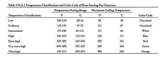
All spot-type heat detectors, whether rate-compensated or fixed-temperature, shall be legibly marked with a color coding and operating temperature in accordance with Section 17.6.2.2. Table 17.6.2.1 provides us with the temperature classification based on the color-coding of the detector.

Location and Spacing of Heat-Sensing Detectors
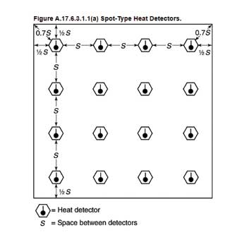
When installing heat detectors on smooth ceilings, they shall be spaced in accordance with Section 17.6.3. The code gives designers and installers two options to choose from. Detectors shall not exceed their listed spacing, and there shall not be more than one-half of their listed spacing between the detector and walls or partitions that exceed 15 percent of the ceiling height or that all points on the ceiling shall have a detector within a distance equal or less than 0.7 times the listed spacing. For any irregular-shaped rooms, the detectors can exceed their listed spacing but shall not be further than 0.7 times the listed spacing from any wall or partition.
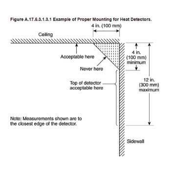
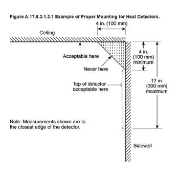
Section 17.6.3.1.3 specifies the location requirements for heat detectors. If installed on ceilings, heat detectors shall be installed not less than 4 in. (100 mm) from the side wall. If installed on the side wall, the detectors shall be installed between 4 inches and 12 inches (100 mm and 300 mm) from the ceiling. Keep in mind that heat fills the corners, and smoke has a rolling effect; the required location ensures that the device functions properly. If beams are present on the ceiling, other requirements are required. If beams project 4 inches or less, the ceiling shall be treated as a smooth ceiling. When beam project more than 4 in. (100 mm) below the ceiling, spacing requirements shall be limited to two-thirds of the listed spacing measured at the right angles to the direction of beam travel in accordance with Section 17.6.3.3.1.1. Where beams project more than 18 in. (460 mm) below the ceiling and are more than 8 ft. (2.4 m) on center shall be treated as separate rooms.
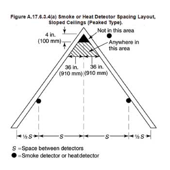
When installing heat detectors on sloped and peaked ceilings, additional rules apply in accordance with Section 17.6.3.4. When installing detectors on sloped ceilings that are less than 30 degrees, the spacing shall be based on the height of the actual peak of the ceiling. When installing detectors on slopes 30 degrees or greater, the spacing shall be based on the average of the height of the peak. Keep in mind too, when installing heat-detectors on sloped and peaked ceilings, the first row of detectors shall be installed within 36 in. (910 mm) of the peak of the ceiling.
On high ceilings, 10 ft. to 30 ft. (3.0 m to 9.1 m), heat detector spacing shall be reduced by using the values given in Table 17.6.3.5.1. Use the listed spacing and multiply the spacing to ensure proper reduction and compliant coverage. Even though Table 17.6.3.5.1 specifies heat detector reduction, just know that in accordance with Section 17.6.3.5.3, heat detectors are never required to be spaced less than 0.4 times their listed spacing.
Smoke-Sensing Fire Detectors
A smoke detector is a device that doesn’t sense thermal energy, but smoke which often indicates a fire. Smoke detectors can detect smoke by optical means (photoelectric) or by a physical process (ionization). Some smoke detectors use both types of technology, photoelectric and ionization.
The general requirements for smoke detectors are located in Section 17.7.1. Smoke detectors shall be installed in accordance with all governing laws, codes, and standards. When designing and installing systems, always pay close attention to the selection and placement of smoke detectors so as not to create a nuisance and unintentional alarms due to improper installation. There should also be an evaluation of potential ambient smoke, moisture, dust, fumes, and electrical and mechanical influences to reduce unwanted or unintentional alarms. Unless a smoke detector is specifically listed for the purpose, it shall not be installed in temperatures below 32 degrees Fahrenheit, temperatures above 100 degrees Fahrenheit, in areas with relative humidity above 93 percent, and in areas with air velocity over 300 ft./min (1.5 m/sec).
At times, especially when rehabbing existing occupancies, smoke detectors are required to stay in service and active during times of construction. Section 17.7.1.12 specifies that if they are left in service during times of construction, they shall be protected from debris, dust, dirt, and damage in accordance with the listings and shall be verified to be operating in accordance with the listed sensitivity. The other option is to replace the detectors before the final acceptance test.
Smoke detectors shall be marked with their nominal production and tolerance in percent per foot. Smoke detectors that allow for field adjustment of sensitivity shall have an adjustment range not less than 0.6 percent per foot obscuration in accordance with Section 17.7.2.2.
Location and Spacing of Smoke-Sensing Detectors
Section 17.7.3.1 outlines the general requirements when locating and spacing smoke detectors. When spacing and locating smoke detectors, the design should be based on the anticipated smoke flows and the ceiling jet produced by the anticipated fire, and any ambient airflows that could exist before the fire. There are other aspects that contribute to the design as well, like ceiling height, shape, and surface, the configuration of the contents in the protected area, combustion characteristics, ventilation, and the ambient temperature, pressure, and atmosphere.
The specific requirements for spot-type smoke detectors are located in Section 17.7.3.2. Spot-type smoke detectors shall be located on the ceiling, or if installed on the sidewall, shall be located within 12 in. (300 mm) from the ceiling on the sidewall. Spot-type detectors installed under raised floors shall be installed as specified by the manufacturer’s instructions to prevent a collection of dust and debris.
On smooth ceilings, spot-type smoke detectors shall not exceed a nominal spacing of 30 ft. (9.1 m). There shall not exceed a distance of one-half nominal spacing from all walls or partitions upward within the top 15 percent of the ceiling height, or all points on the smooth ceiling shall have a detector within 0.7 times the nominal spacing (21 ft.) Regardless, in all cases, the manufacturer’s instructions shall be followed. It is an option for designers to use other spacing requirements dependent on the ceiling height, different conditions, or response requirements if the AHJ approves in accordance with Section 17.3.2.3.3. The documents used for design and approval should become a document kept with that system for the life of the system.
When installing spot-type detectors on a ceiling with solid joists and beams, Sections 17.7.3.2.4.1 through 17.7.3.2.4.6 shall be used to determine the spacing requirements. Solid joists are equivalent to beams when spacing requirements are considered.
For leveled ceilings, when the beam depths are less than 10 percent of the ceiling height, smooth ceiling spacing shall be permitted, and the designer or installer can place the detector on the ceiling or the bottom of the beam. For beam depths that are equal or greater than 10 percent, one of the two following conditions shall apply. Where beam spacing is less than 40 percent of the ceiling height (0.4 H), the detectors can be placed on the ceiling or the beam, and smooth ceiling spacing shall be based on measuring from the direction parallel to the beams measure at one-half the direction perpendicular to the beams. For beam pockets formed by intersecting joists or beams, including waffle or pan-type ceilings, each pocket shall be treated as an individual space if the beams are equal or greater than 40 percent of the ceiling height.
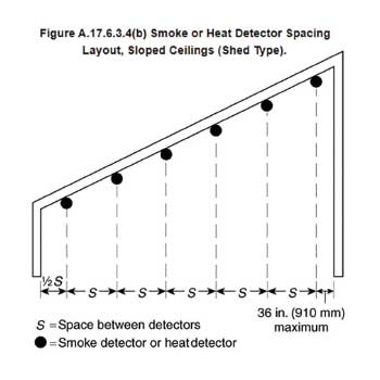
For peaked ceilings, a row of detectors shall be spaced and located within 36 in. (910 mm) of the peak measured horizontally in accordance with 17.7.3.3. The number and spacing of additional detectors shall be based on the horizontal distance of the ceiling. Section 17.7.3.4 details that detectors shall first be spaced and located within 36 in. (910 mm) of the high side of the ceiling. Additional detectors shall be based on the horizontal projection of the ceiling.

Air Sampling-Type Smoke Detectors
An air sampling-type detector is a detector system that consists of a tubing system with ports that draw air samples by way of aspirating fans at the controller to check for fire particles. The tubing network protects the specified area and acts as a multiple detector throughout. In accordance with Section 17.7.3.6.1.1, each port of the air sampling-type detector shall be treated as a spot-type detector for spacing considerations. If the system has an atmospheric filtration system, it shall be listed for use in accordance with the manufacturer’s published instructions. The detector will have a specified range and shall initiate a trouble signal if outside of that range.
The pipe and tubing network is covered in Section 17.7.3.6.2. The maximum transport time for the air samples shall not exceed 120 seconds. The sampling pipe network shall be designed using computer-based fluid dynamics calculations to ensure proper support, pressure, flow, and alarm sensitivity at each sampling port. Sampling systems shall be identified as “SMOKE DETECTOR SAMPLING TUBE – DO NOT DISTURB” at changes in direction or branches of tubing, on each side when making penetrations through walls, floors, and other barriers, and at intervals not greater than 20 ft. Sampling ports shall also be identified. All supports for the sampling tubes shall be in accordance with the manufacturer’s instructions.
Projected Beam-Type Smoke Detectors
A beam-type detector is a device that uses a projected beam of light to detect smoke in large areas that indicate a fire. Once the light is obscured by smoke and cannot detect the light into the sensor, it initiates an alarm signal. Beam-type detectors are used to cover large areas and high atriums where smoke detectors would be ineffective due to smoke stratification.
Section 17.7.3.7 covers the requirements for projected beam-type smoke detectors. During the design phase, the effects of possible stratification shall be evaluated. The detectors shall be located in accordance with the manufacturer’s instructions. The beam length shall not exceed the recommended distance, and if mirrors are used, they need to be installed per the manufacturer’s instructions. The mirrors shall be installed on stable surfaces to prevent nuisance and unintentional alarms. The light path for beam-type detectors shall be kept clear at all times. For spacing purposes, beam-type detectors are considered equivalent to a row of spot-type detectors.
Sprinkler Waterflow Alarm-Initiating Devices
A waterflow alarm-initiating device is a switch that detects the movement of waterflow in a suppression system. The switch has a paddle that closes or opens contacts when water is flowing and initiates an alarm signal to generate evacuation, notification, and emergency response. Due to water movement and air pockets, there is usually a delay on the signal initiation to avoid nuisance and unintentional alarm signals.
Section 17.13 covers the requirements for sprinkler waterflow alarm-initiating devices. The activation of the initiating device shall occur within 90 seconds at the alarm-initiating device when flow occurs that is equal or greater than the smallest orifice installed in the system. Section 17.13.3 states that movement due to water, surges, or variable pressure shall not initiate an alarm signal.
Manually Actuated Alarm-Initiating Devices
A manual actuated alarm-initiating device is different from an automatic alarm initiating device because it requires human intervention to initiate a signal. If a person sees an emergency, they can manually pull the station and generate an emergency response. Manually actuated devices fall into two separate categories: single pull and double pull stations.
Section 17.15 covers manually actuated alarm-initiating devices, also known as pull stations. All manual alarm initiating devices shall be listed in accordance with standards such as ANSI/UL 38, Standard for Manual Signaling Boxes for Fire Alarm Systems. It is permissible to use manual fire alarm boxes for guards signaling stations as well. All manual actuated devices shall be securely mounted and protected from physical damage. All protective devices shall be listed for use with the manual alarm devices, and protective covers can be used for single or double action devices.
Manual actuated devices shall be red in color unless the environment it is installed in will not allow red paint or plastic. The devices shall be mounted on a background of contrasting colors. It’s important that the manually actuated devices can be spotted easily during times of emergency. They shall be installed so that they are conspicuous, unobstructed, and accessible to anyone who is looking for one.
Governing laws, codes, and standards specify when manual actuated devices are required and where they are required per the occupancy type. When required, they shall be installed within 5 ft. (1.5 m) of each exit doorway on each floor. Additional manual fire alarm boxes shall be installed so that the travel distance will not exceed 200 ft. (61 m) to the nearest device. Just note, that means 400 ft. (122 m) between devices; if a person is in the middle, that is 200 ft. (61 m) to either device. In larger openings or storefronts, a manual actuated device shall be put on either side of the opening unless the opening exceeds 40 ft. (12.2 m); if it exceeds 40 ft. there shall be a manually actuated device on both sides.
Conclusion
Protecting lives and property is the most important aspect of our industry. The industry and each of us act as the silent and invisible protectors by using the governing laws, codes, and standards to ensure that this level of protection is the priority of our jobs. Remember to do your part and stay active in any updated cycles or additions to these laws, codes, and standards. Always put the daily stress, minute issues, and time constraints aside when it comes to protecting life and property. Stay focused on the goal at hand! By spending a little extra attention now, understanding the goals and risk, you may save someone’s life or business in the future.