Being from the great state of Texas, there is nothing better and more reassuring than a comfortable pair of cowboy boots. The key to a good pair of boots is selecting the proper size. Being a little off on the size one way or the other can make all the difference in the world as far as the coziness of this stylish footwear. Nothing can be more uncomfortable than squeezing into a pair of boots that are too small, and a pair of boots that are too big can result in blisters from the leather rubbing back and forth on your skin. The same can be said for the sizing of electrical conductors, with the consequences being far greater than simple comfort. Selecting the wrong size conductor in an electrical installation can have dangerous and disastrous results with conductors too small for the applied load. And who wants to pay the unnecessary and added expense of conductors sized larger than necessary?
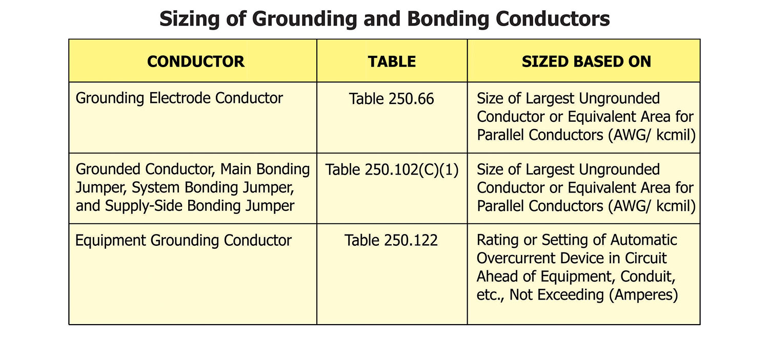
If you are in the electrical industry, there are several conductors related to grounding and bonding that we refer to and use on a daily basis. Proper sizing of these grounding and bonding conductors is a critical part of the proper installation of an electrical system. In this article, we will take a look at the proper sizing of some of these critical grounding and bonding conductors. In the National Electrical Code (NEC), there are three main tables that we will use to size these grounding and bonding conductors. First, we have Table 250.66 (Grounding Electrode Conductor for Alternating Current Systems). Then we have Table 250.102(C)(1) (Grounded Conductor, Main Bonding Jumper, System Bonding Jumper, and Supply-Side Bonding Jumper for Alternating-Current Systems), and finally, we have Table 250.122 (Minimum Size Equipment Grounding Conductors for Grounding Raceway and Equipment). We will discuss all of these tables in greater detail throughout the following article.
Sizing of the Grounded Service Conductor
When discussing grounding and bonding, it is critical to use proper terminology. When someone calls my office and says, ”I have a grounding question,” and then they will say something like, “I want to talk about that ‘grounding conductor’ I’m required to run to my service.” In a case like this, the first thing we have to do is properly define what “grounding conductor” they are referring to. When dealing with grounding and bonding, it is imperative to get everyone on the same page by using proper and defined terms used in the NEC. With that in mind, let’s define what conductor we are referring to before we discuss the sizing of said conductors. In Article 100, the NEC defines the Grounded Conductor as “a system or circuit conductor that is intentionally grounded.”
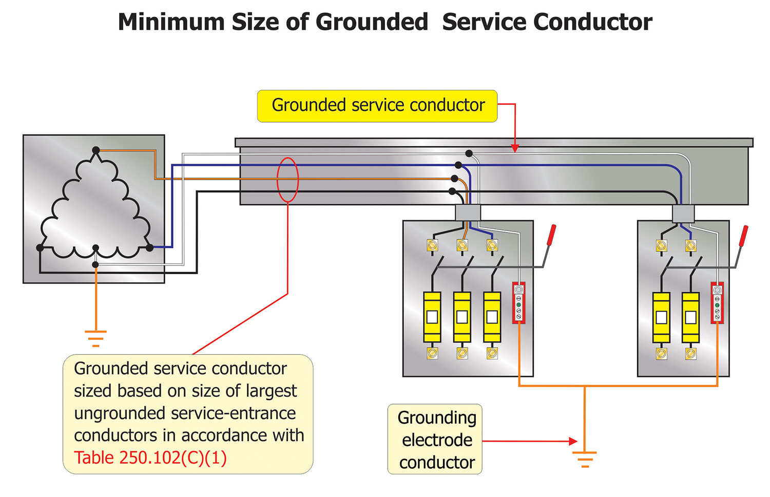
An important set of requirements for grounded service conductors are found at 250.24(C). This section requires that where an ac system operating at 1000 volts or less is grounded at any point, the grounded conductor (usually a neutral conductor) is required to be run to each service disconnecting means and bonded to the enclosure (typically through the main bonding jumper).
The basic requirements for sizing of the grounded (neutral) service conductor vary with the load as calculated in accordance with 220.61. The initial calculation from 220.61 becomes the minimum size grounded service conductor unless modified by 250.24(C)(1) or (C)(2).
First, a load calculation should be performed in accordance with 220.61 to determine the minimum size for the anticipated neutral load. Second, a conductor size must be determined from 250.24(C)(1) or (C)(2). Section 250.24(C)(1) requires the service grounded conductor to be sized per Table 250.102(C)(1) or per Note 1 to Table 250.102(C)(1). The final minimum service grounded conductor size must be the larger result as determined from these two calculations. Using this table, the grounded service conductor would be sized based on the size of the largest ungrounded conductor or equivalent area for parallel conductors (AWG/kcmil). As an example, a service consisting of a 250 kcmil copper conductor per phase would demand a minimum sized grounded conductor for this service of 2 AWG copper or 1/0 AWG aluminum or copper-clad aluminum conductors. If a service consisted of three 250 kcmil copper conductors per phase in parallel (750 kcmil), the grounded conductor would need to be sized at a minimum of 2/0 AWG copper or 4/0 AWG aluminum or copper-clad aluminum conductors.
Note 1 to Table 250.102(C)(1) introduces the “12 ½ percent rule.,” which states that if the ungrounded supply conductors are larger than 1100 kcmil copper or 1750 kcmil aluminum [which is as large as Table 250.102(C)(1) indicates], the grounded conductor would be required to have an area not less than 12½ percent of the area of the largest ungrounded supply conductor or equivalent area for parallel supply conductors. An example of this would be a service with six 4/0 AWG copper conductors per phase. How many circular mils is in each 4/0 AWG copper conductor? For this answer, we will need to visit NEC Chapter 9, Table 8. This Chapter 9 table reveals that a 4/0 AWG copper conductor consists of 211,600 circular mils. In our example, we have six of these conductors per phase.
Quick math would tell us that these (6) 4/0 AWG copper conductor is the equivalent of 1,269,600 circular mils [6 X 211,600 = 1,269,600 cm]. This total circular mil value exceeds the largest referenced copper 1100 kcmil value found at the bottom of Table 250.102(C)(1). Per Note 1 to Table 250.102(C)(1), we would now have to apply the “12 ½ percent rule” to these 1,269,600 circular mils to reveal the minimum size grounded conductor needed for these six 4/0 AWG copper conductors per phase. Again, our quick math would indicate that 12 ½ percent of 1,269,600 circular mils is 158,700 circular mils [1,269,600 cm x .125 = 158,700 cm]. To select a grounded service conductor with at least this 158,700 circular mils value, we will need to go back to Chapter 9, Table 8. According to Table 8, a 2/0 AWG conductor equals 133,100 circular mils, whereas a 3/0 AWG conductor consists of 167,800 circular mils, so a 3/0 AWG copper would be the minimum size grounded service conductor for six 4/0 AWG copper ungrounded conductors per phase.
Sizing the Grounding Electrode Conductor(s)
For clarification, Article 100 of the NEC defines a Grounding Electrode as “a conducting object through which a direct connection to earth is established.” A Grounding Electrode Conductor is defined as “a conductor used to connect the system grounded conductor or the equipment to a grounding electrode or to a point on the grounding electrode system.”
For sizing a grounding electrode conductor (GEC) for a single service, the grounding electrode conductor is required to be sized in accordance with 250.66 and Table 250.66. That conductor is required to be a minimum size of 8 AWG copper and need not be larger than 3/0 AWG copper. Where aluminum or copper-clad aluminum grounding electrode conductors are installed, they are required to be not smaller than 6 AWG or larger than 250 kcmil. The size of the grounding electrode conductor is based upon the size of the largest ungrounded service-entrance conductors or ungrounded derived conductors (such as for a separately derived system) or the total equivalent area for parallel conductors (AWG/kcmil).
Table 250.66 is based on a conductor size relationship and not on the rating of the circuit breaker or fuse in the service equipment. For example, where 3/0 AWG copper service-entrance conductors are installed, the minimum-sized grounding electrode conductor is 4 AWG copper or 2 AWG aluminum. If 750-kcmil aluminum service-entrance conductors are installed, a 1/0 AWG copper or 3/0 AWG aluminum grounding electrode conductor would be required to be used. Any ungrounded service conductors sized over 1100 kcmil copper or over 1750 kcmil aluminum or copper-clad aluminum would require a grounding electrode conductor of a maximum size of 3/0 AWG copper or 250 kcmil aluminum or copper-clad aluminum conductors
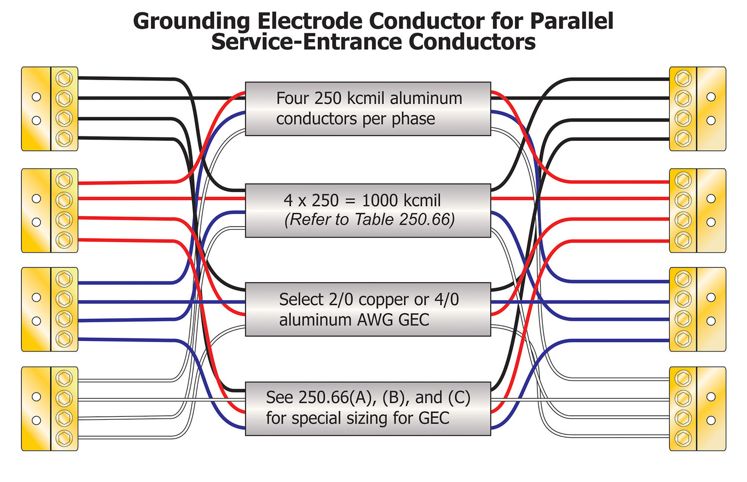
Where service-entrance conductors are installed in parallel [as allowed by 310.10(G)], the circular mil area of one set of parallel conductors is added together and treated as a single conductor for purposes of sizing a GEC. An example of this would be four 250-kcmil aluminum service-entrance conductors installed in parallel are considered to be a single 1000-kcmil aluminum conductor. According to Table 250.66, these four 250-kcmil aluminum service-entrance conductors would demand a 2/0 AWG copper or 4/0 aluminum or copper-clad aluminum GEC conductor.
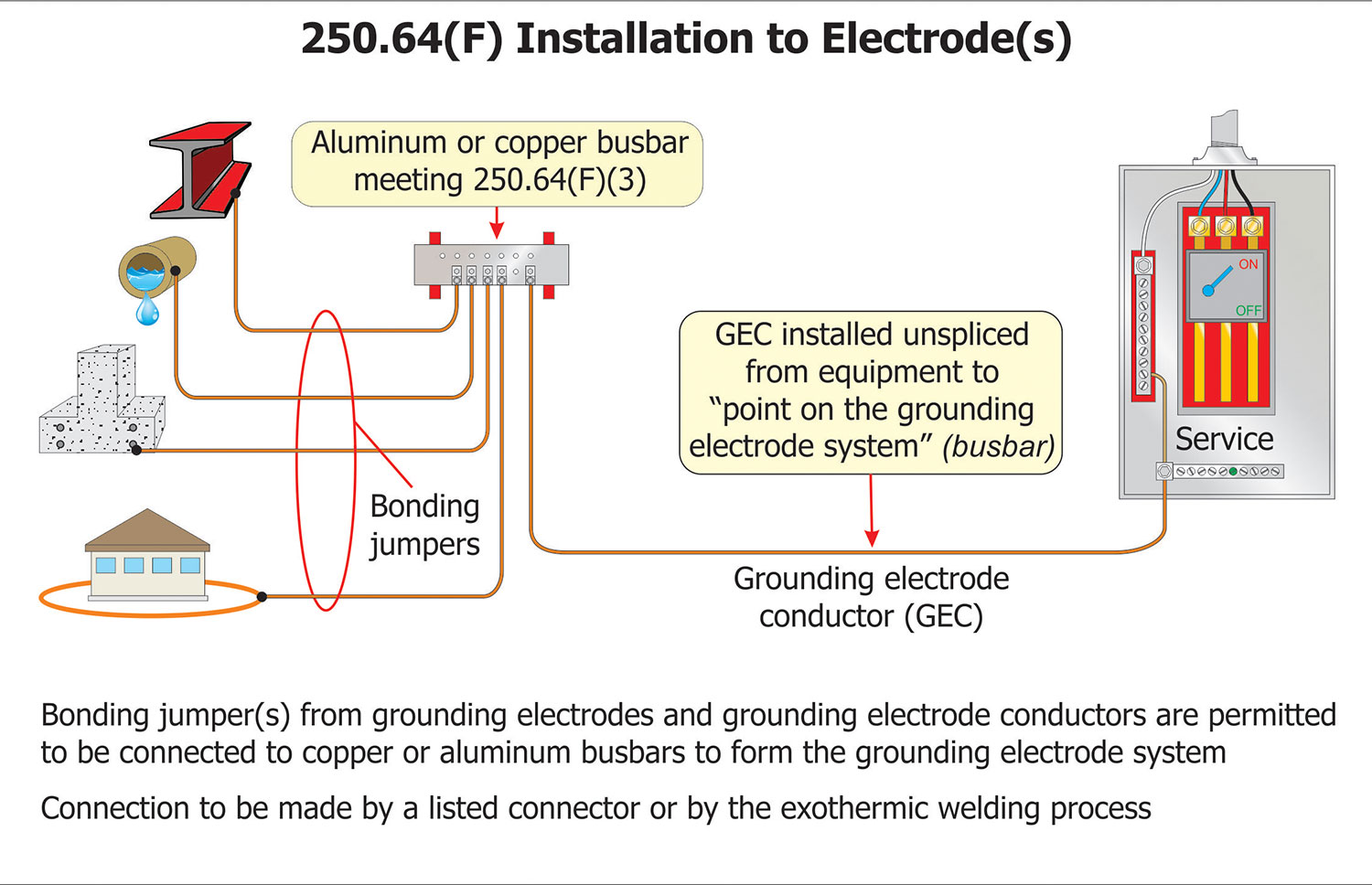
For sizing grounding electrode conductors for multiple enclosure services, 250.64(D) provides four options to make this installation. Services are permitted to be installed in up to six separate enclosures installed at one location under certain conditions. In these cases, the method of sizing grounding electrode conductors is a matter of choice for the designer or installer. One basic rule must be followed: size the grounding electrode conductor for either the circular mil area of service-entrance conductor(s) at the point of connection for each service disconnect or size it as a common grounding electrode conductor based on the size of the main service-entrance conductor(s).
Section 250.64(D)(1) provides two options. One option permits a single wire type common grounding electrode conductor to serve the separate service enclosures. This wire type common grounding electrode conductor is sized based on the main service-entrance conductors. The second option is to use a busbar as the common grounding electrode conductor. The bus bar is required to be sized a minimum of 6 mm × 50 mm (¼ in. x 2 in.) and whatever length is needed for all the connections. The busbar is permitted to be made of copper or aluminum. For both options, grounding electrode conductor taps that are sized based on the individual service-entrance conductors supplying each service disconnect are then connected from within each service disconnecting means to the common grounding electrode conductor, wire, or busbar. It is important to understand that the alternative provided in 250.64(D)(1) addresses two conductors; the common grounding electrode conductor that is required to be installed without a splice or joint (generally) and the grounding electrode conductor tap(s) that are permitted to be connected to the common grounding electrode conductor. It should also be noted here that the conductors from the individual grounding electrodes to the permitted busbar are not grounding electrode conductors but are bonding jumpers.
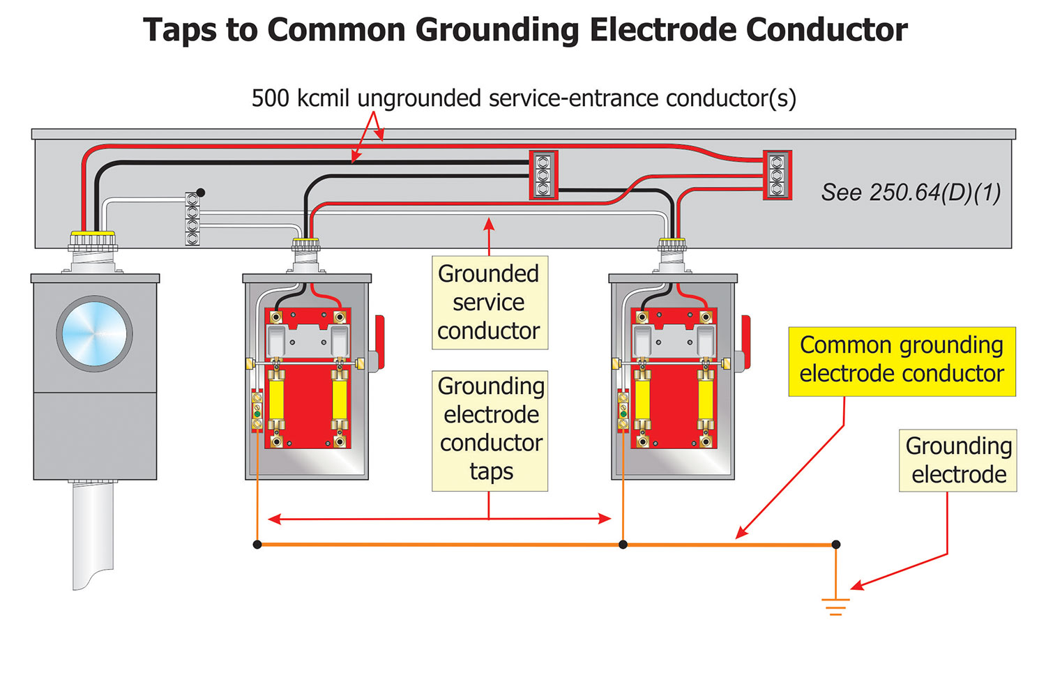
An example of this would be to assume that 500-kcmil copper main service-entrance conductors supply a service and are connected in a wireway to the 2 AWG copper service-entrance conductors that serve each of three service enclosures. Referring to Table 250.66, the minimum size wire-type common grounding electrode conductor would be 1/0 AWG copper or 3/0 AWG aluminum or copper-clad aluminum conductors. This common GEC conductor is installed from the grounding electrode to the vicinity of the wireway. The grounding electrode tap conductors from the individual enclosures are sized from Table 250.66 and are either 8 AWG copper or 6 AWG aluminum or copper-clad aluminum conductors.
Another option for the installer is to install a grounding electrode conductor from the individual service disconnects to the grounding electrode(s) rather than being tapped to the common grounding electrode conductor as provided in 250.64(D)(2). In this case, the grounding electrode conductors are sized for the service-entrance conductor serving each individual enclosure. Using this option, a grounding electrode conductor from each of the service disconnects would be required to be installed to each of the grounding electrodes in the system. Where multiple grounding electrodes are present, it is not permitted to install the grounding electrode conductor from one service enclosure to only one grounding electrode and not utilize the other present electrodes.
And finally, the last option available, as provided in 250.64(D)(3), is to install a single grounding electrode conductor to a wireway or other location common to all the connected individual service-entrance conductors. For the example described earlier, assume the 500-kcmil copper service-entrance conductors and the service-entrance grounded conductor are grounded inside a wireway. By reference to Table 250.66, we find that the grounding electrode conductor to a water pipe or building steel grounding electrode is required to be 1/0 AWG copper or 3/0 AWG aluminum or copper-clad aluminum conductors.
Alternate Sizing of Grounding Electrode Conductors
Grounding electrode conductors are generally required to be not smaller than the values in Table 250.66 based on the size of the largest ungrounded service-entrance conductor or largest ungrounded conductor of a separately derived system. For certain grounding electrode(s), an alternate sizing allowance is provided in the parent text of 250.66(A) through (C). Where connected to a rod, pipe, or plate electrode, 250.66(A) permits the grounding electrode conductor or bonding conductor to be not larger than 6 AWG copper or 4 AWG aluminum. The main reason for this is the ability of rod(s), pipe(s), or plates to dissipate energy into the earth. A change to this section was made in the 2014 NEC clarifying that the 6 AWG copper or 4 AWG aluminum grounding electrode conductor is the maximum required with single or multiple rods, pipes or plates, or any combination of rods, pipes, and plates. Additional changes were added in the 2017 NEC to add “bonding jumpers” and remove the reference to a “sole connection.” This change allowed this alternate maximum size only where no other grounding electrodes requiring a larger grounding electrode conductor or bonding jumper (such as an underground metal water pipe electrode) being connected to the rod, pipe, or plate electrode(s) that extends the grounding electrode system.
Section 250.66(B) provides that the grounding electrode conductor connection to a concrete-encased grounding electrode needs not be larger than 4 AWG copper. Note that aluminum conductors are not permitted for this application. The use of this smaller conductor is based on the fact that it will never need to carry a current beyond its safe short-time rated capacity, even under ideal conditions. If a grounding electrode conductor is installed to multiple concrete-encased electrodes connected together with a bonding jumper(s), the maximum size grounding electrode conductor to the first concrete-encased electrode or any bonding jumper(s) between the multiple concrete-encased electrodes is not required to be larger than a 4 AWG copper conductor. A clarification was added in the 2017 NEC, similar to the one for rods, pipes, and plates, to remove the reference to a “sole connection” and to allow this maximum size only where no other grounding electrodes requiring a larger grounding electrode conductor or bonding jumper are then connected to the concrete-encased electrode(s) extending the grounding electrode system.
Section 250.52(A)(4) requires that the minimum size conductor and material for a ground ring is 2 AWG copper. Section 250.66(C) provides that where connected to a ground ring, that portion of the grounding electrode conductor that is connected to the ground ring need not be larger than the ground ring conductor. That is because the electrode resistance is the limiting factor in the circuit, and increasing the grounding electrode conductor size would not serve any useful purpose. Design engineers will sometimes specify ground rings of 4/0 AWG or 250 kcmil. In this case, follow the requirements in Table 250.66 to determine the required minimum grounding electrode conductor size. Then the allowance of not being larger than the ground ring electrode can be applied. Keep in mind that the grounding electrode conductor is not required by the NEC to be larger than 3/0 AWG copper or 250-kcmil aluminum or copper-clad aluminum under any circumstances. As was done for rods, pipes, plates, and concreted encased electrodes, a clarification was added in the 2017 NEC to remove the reference to a “sole connection.” This will allow the maximum size only where no other grounding electrodes requiring a larger grounding electrode conductor or bonding jumper are then connected to the ground ring electrode extending the grounding electrode system.
What the provisions of 250.66(A), (B), or (C) give to the installer is the ability to create a “daisy chain” of grounding electrodes with bonding jumpers. Where the next type of electrode in the “daisy chain” has a maximum allowance per 250.66(A), (B), or (C) and there are no other electrodes extended beyond these electrodes requiring a larger conductor, the alternate maximum size conductor can be used. For example, for a large service requiring a 3/0 copper grounding electrode conductor, the conductor to the metallic water pipe would be 3/0 copper. Going from the metallic water pipe to a 2 AWG copper ground ring would only require a 2 AWG copper bonding jumper. From the ground ring to the concrete-encased electrode would only require a 4 AWG copper, and then to the one or more ground rods, pipes or plates would only require a 6 AWG copper. If the above sequence were changed, then the allowance for stepping down the bonding jumper would not be applicable.

Sizing Bonding Jumper(s) for the Grounding Electrode System
Section 250.53(C) requires bonding jumper(s) used to connect the grounding electrodes of a grounding electrode system together to be installed in accordance with the requirements of 250.64(A), (B), and (E). The bonding jumper used to bond the grounding electrodes together to form the grounding electrode system are required to be sized in accordance with 250.66 and Table 250.66 based on the size of the ungrounded service-entrance conductor and is required to be connected in a manner specified in 250.70 (methods of grounding and bonding conductor connections to electrodes). The conductor that connects the grounding electrodes together is a bonding jumper and not a grounding electrode conductor. Bonding jumpers are not required to be installed in one continuous length as grounding electrode conductors. In addition, the alternate allowances provided in the parent text of 250.66(A) through (C) discussed earlier for sizing the grounding electrode conductor apply for the sizing of these bonding jumpers as well.
Sizing of Equipment Grounding Conductors
A closer look at NEC Article 100 reveals that the definition of an Equipment Grounding Conductor is “a conductive path(s) that is part of an effective ground-fault current path and connects normally non-current-carrying metal parts of equipment together and to the system grounded conductor or to the grounding electrode conductor, or both.” A review of this definition clearly shows that the equipment grounding conductor (EGC) performs both grounding and bonding functions, and that is reinforced by an Informational Note following the definition. Acceptable wiring methods that qualify as their own equipment grounding conductor and other EGCs are listed at 250.118. Starting at the service, you will have a large overcurrent protective device that is in series with other (and usually smaller) feeder or branch overcurrent protection devices. The ungrounded (phase or hot) conductor usually decreases in size as it progresses through smaller and smaller overcurrent devices. Specific requirements for sizing equipment grounding conductors are provided at the following Code references: General sizing requirements, 250.122(A); EGCs that are increased in size, 250.122(B); EGCs for multiple circuits, 250.122(C); Motor circuit EGCs, 250.122(D); Flexible cord and fixture wire EGCs, 250.122(E); and EGC conductors in parallel, 250.122(F).
Section 250.122(A) provides the general requirements for sizing an equipment grounding conductor. This section refers to Table 250.122 for determining the minimum size of a conductor that is required to be used as an equipment grounding conductor. This table sizes EGCs based on the ampere rating of the overcurrent protective device ahead of the conductor, unlike the other previous tables we used [Table 250.66 and Table 250.102(C)(1)] that are based on the size of the ungrounded phase conductors for sizing various grounding and bonding conductors.
For example, using Table 250.122, if the overcurrent protection ahead of a circuit or feeder is 225 amperes, the minimum size equipment grounding conductor is found as follows: In Table 250.122, follow the first column, which gives the rating of the overcurrent device, down to find the rating that equals or exceeds 225 amperes. Since 225 amperes is not found, go to the next larger size, which is 300 amperes. The 225-ampere rating is greater than the 200-ampere row but less than the 300-ampere row. Follow that line across to find the minimum size copper wire EGC to be 4 AWG, and for aluminum or copper-clad aluminum, a 2 AWG minimum size EGC would be required.
Follow a similar process to determine the minimum size conductor for any installation. For some installations, the minimum provided in Table 250.122 is inadequate. For these situations, the note below Table 250.122 states that, “where necessary to comply with 250.4(A)(5) or 250.4(B)(4), the equipment grounding conductor shall be sized larger than given in this table.” Notes that are part of tables in the NEC are mandatory (unlike Informational Notes). The two main reasons this note needs to be applied are: (1) Very high fault current that can damage or melt the equipment grounding conductor and (2) Long lengths that must be compensated for to provide the low impedance path to operate the overcurrent device.
Section 250.122(B) requires that “if ungrounded conductors are increased in size for any reason other than as required in 310.15(B) and 310.15(C), wire-type equipment grounding conductors, if installed, shall be increased in size proportionately according to circular mil area of the ungrounded conductors.” An example of an increase in size for the ungrounded conductors might be to compensate for voltage drop concerns over a long branch circuit or feeder. This means that where a feeder or branch-circuit conductor is increased in size (except for the application of correction or adjustment factors), the wire type equipment grounding conductor for this circuit would be required to be increased at not less than the same ratio the feeder or circuit conductors are increased.
For example, a 200-ampere feeder is to be installed across a large building. It is determined that the voltage drop would be excessive for this feeder. A 250-kcmil copper conductor is selected for the feeder rather than installing the 3/0 AWG copper conductor that would be required for 200 amperes by Table 310.16. Table 250.122 normally requires a 6 AWG copper equipment grounding conductor for the 200-ampere overcurrent device. To determine the minimum size equipment grounding conductor required for this feeder, we would need to follow the formula found in Figure 6. Once again, we will need to use Table 8 of NEC Chapter 9 to determine the area in circular mils where the conductor size is given by a non-circular mil designation (AWG).
Sizing Equipment Grounding Conductors for Multiple Circuits
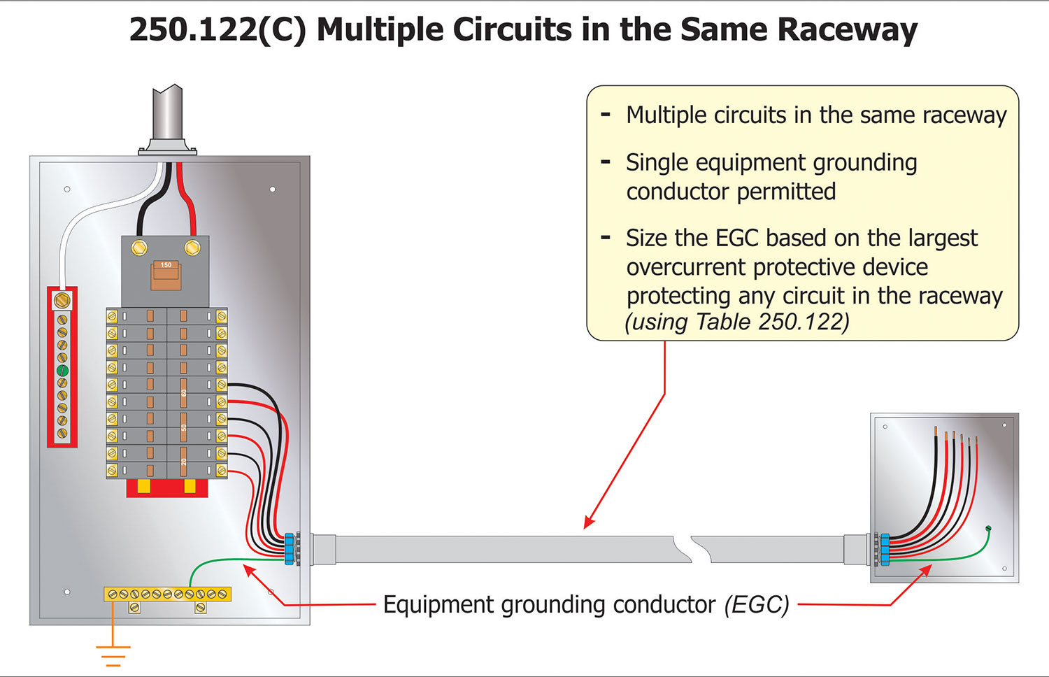
Section 250.102(C) permits a single equipment grounding conductor to serve multiple circuits that are installed in the same raceway, cable, or cable tray. To use this multi-circuit concept, the equipment grounding conductor would be required to be sized based on the rating of the largest overcurrent device protecting any of the circuits of the group. As an example, a conduit containing four branch circuits that have overcurrent protection rated 20-amperes, 30-amperes, 50-amperes, and 60-amperes. A single 10 AWG equipment grounding conductor is permitted to serve all the branch circuits in the single raceway. The minimum size single 10 AWG equipment grounding conductor is determined from Table 250.122 based on the rating of the largest overcurrent device (60-ampere). This same concept can be used where multiple raceways requiring bonding enter an enclosure with a single equipment bonding jumper (sized the same as an equipment grounding conductor for multiple circuits) being installed for all the bonding bushings [see 250.102(D)]
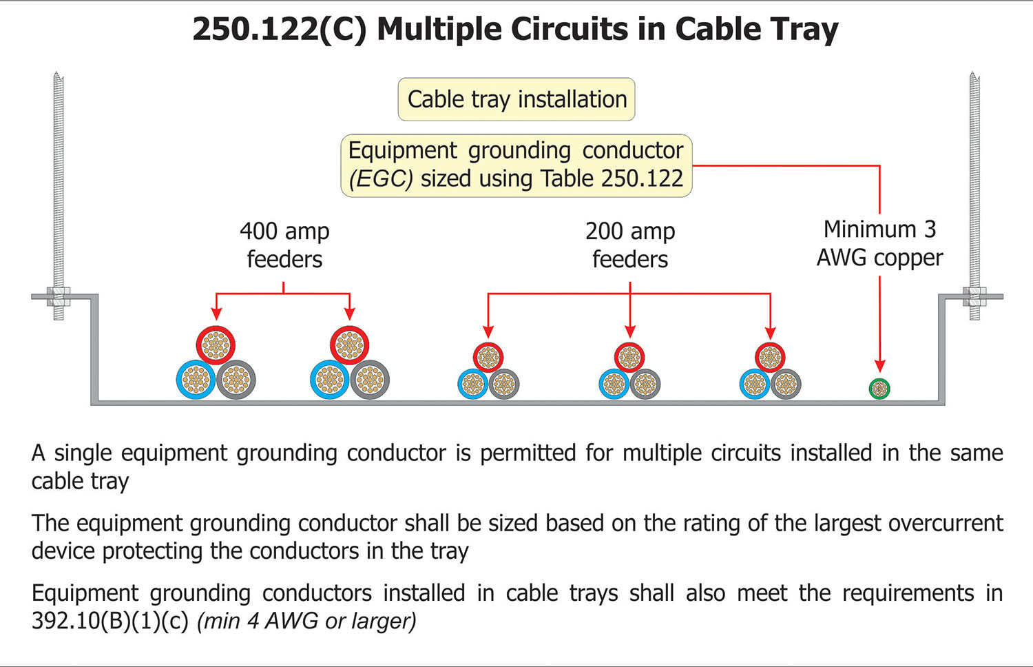
A single equipment grounding conductor is also permitted for multiple circuits installed in the same cable tray. As with a single raceway containing multiple circuits, the equipment grounding conductor would be sized based on the rating of the largest overcurrent device protecting any of the circuits contained in the cable tray. This cable tray equipment grounding conductor would also be required to meet the requirements of 392.10(B)(1)(c), which calls for a single conductor used as an equipment grounding conductor in a cable tray to be insulated, covered, or bare, and be sized at a minimum 4 AWG or larger.

Sizing Main Bonding Jumpers
NEC Article 100 defines a Main Bonding Jumper as “the connection between the grounded circuit conductor and the equipment grounding conductor, or the supply-side bonding jumper, or both, at the service.” The key phrase in this definition is “…at the service.” If this bonding jumper were to be installed at a separately derived system, it would be defined as a system bonding jumper.
Where listed service equipment (such as switchgear, switchboards, panelboards, or motor control centers) is installed, the main bonding jumper that is provided with the equipment is rated for the size of conductors that would be installed for the service entrance conductors based on the rating of said service equipment. The method for sizing the main bonding jumper in listed service equipment is found in the product safety standard for the equipment under consideration and is verified by the listing organization (such as UL, ETL, etc.). Therefore, the main bonding jumper that is a busbar, strap, conductor, or screw furnished by the manufacturer as part of the listed equipment can be used without calculating its adequacy.
If a need for wire-type main bonding jumper were to be installed in the field (such as in a wireway supporting service disconnects), this main bonding jumper would need to be sized per 250.28(D), which refers to Table 250.102(C)(1). Because the main bonding jumper must carry the full ground-fault current of the system back to the grounded service conductor (which may be a neutral), its size must relate to the rating of the service conductors which supply the service. For services with service-entrance conductors up to 1100 kcmil copper or 1750 kcmil aluminum, the use of Table 250.102(C)(1) is warranted. Where the service-entrance conductors are larger than these values, Note 1 to Table 250.102(C)(1) requires the main bonding jumper to be a minimum of 12 ½ percent of the cross-sectional area of the largest service-entrance conductor. This relationship is based on the conductor’s ability to carry the expected amount of fault current for the period needed for the overcurrent device to open or operate and interrupt current flow.
Sizing System Bonding Jumpers
The system bonding jumper is the first component for grounding and bonding separately derived systems and is addressed in 250.30(A)(1). A System Bonding Jumper is defined as “the connection between the grounded circuit conductor and the supply-side bonding jumper, or the equipment grounding conductor, or both, at a separately derived system” (see NEC Article 100). The difference between a system bonding jumper and a main bonding jumper is its location. Main bonding jumpers are found at services, and system bonding jumpers are found at separately derived systems. System bonding jumpers are sized the same as main bonding jumpers. System bonding jumpers would need to be sized per 250.28(D), which refers to Table 250.102(C)(1).
Sizing of Supply-Side Bonding Jumpers
The service grounded (neutral) conductor generally provides the electrical continuity between the supply source (such as a utility transformer enclosure) and the various enclosures of the service equipment. Where additional bonding is required in this equipment (such as for bonding bushings on metal raceways), a supply side bonding jumper provides the connection to the service grounded (neutral) conductor in the service equipment enclosure(s). The supply-side bonding jumper functions to carry ground-fault current from ground faults that occur on the supply side of the main overcurrent protection and provide a low impedance path for the ground-fault current to return to the source. The supply-side bonding jumper can be a non-flexible metal raceway or a wire-type conductor. A Supply-Side Bonding Jumper is defined as “a conductor installed on the supply side of a service or within a service equipment enclosure(s), or for a separately derived system, that ensures the required electrical conductivity between metal parts required to be electrically connected” (see Article 100).
Supply-side bonding jumpers on the line side of the service equipment must be sized in accordance with 250.102(C)(1) (singe raceway or cable) or 250.102(C)(2) (parallel conductors installed in two or more raceways or cables). These requirements call for the use of Table 250.102(C)(1), where the service-entrance conductors are smaller than 1100 kcmil copper or 1750 kcmil aluminum. For example, where 250-kcmil copper conductors are installed as service-entrance conductors, Table 250.102(C)(1) requires a 2 AWG copper or 1/0 AWG aluminum conductor for the supply-side bonding jumper.
Where the sum of the circular mil area of the service-entrance phase conductors exceeds 1100-kcmil copper or 1750-kcmil aluminum, in a single raceway, the supply-side bonding jumper must be not less than 12 ½ percent (0.125) of the area of the ungrounded phase conductors. As with the main bonding jumper, if the supply-side bonding jumper is of a different material (copper, aluminum, or copper-clad aluminum) than the service-entrance conductors, then Note 2 to Table 250.102(C)(1) provides the requirements on how to determine the correct supply-side bonding jumper size. The supply-side bonding jumper size would be based on the assumed use of ungrounded supply conductors of the same material as the supply-side bonding jumper. It would be required to have an ampacity equivalent to that of the installed ungrounded supply conductors.
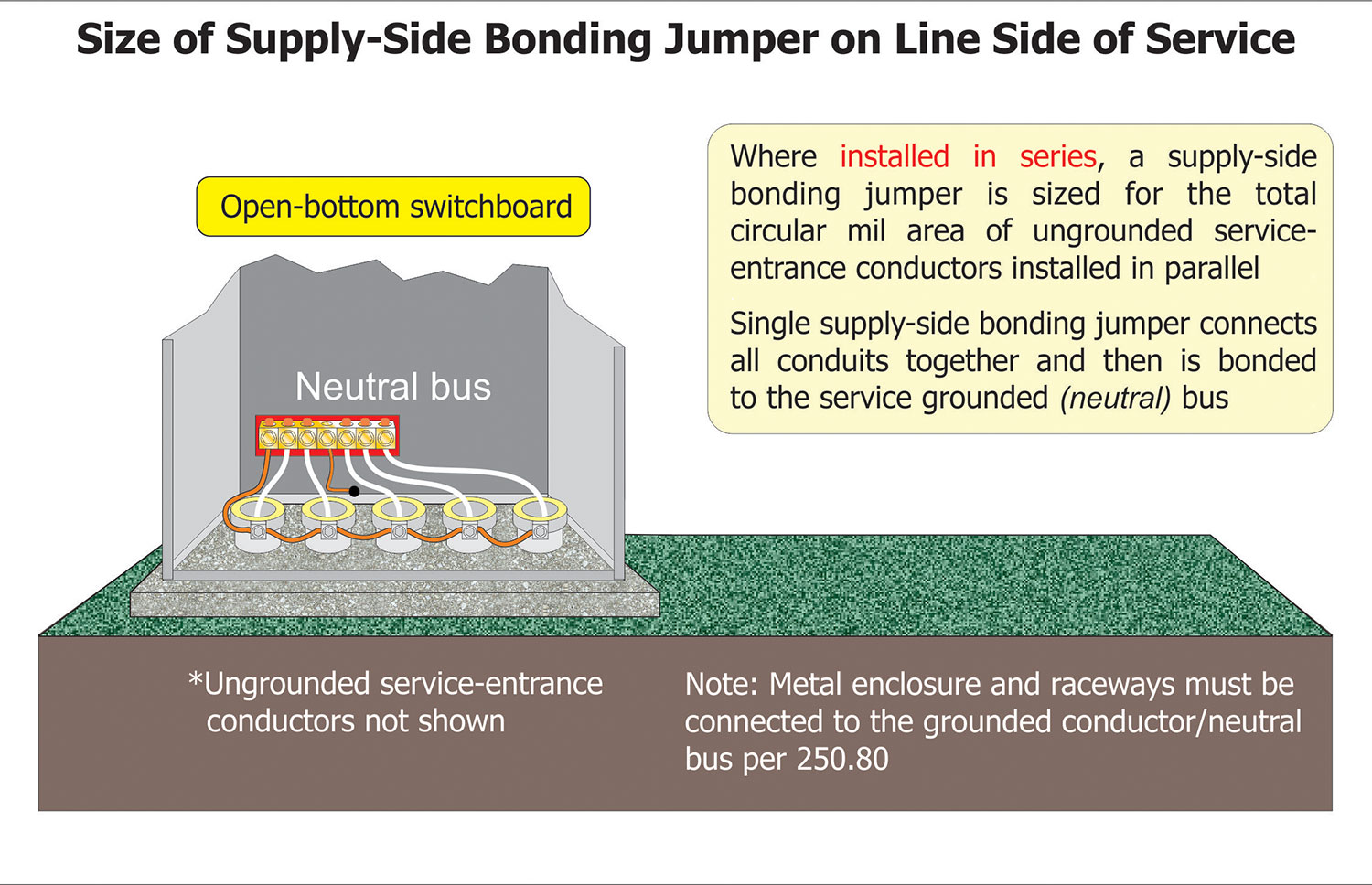
For sizing of supply-side bonding jumper for parallel service conductors, two methods are provided for bonding service raceways that are installed in parallel. The first method is to add the circular mil area of the service-entrance conductors per phase together and treat them as a single conductor. The supply-side bonding jumper size is determined from Table 250.102(C)(1) and is connected to each conduit bonding bushing in a “daisy-chain” fashion. This method often results in a supply-side bonding jumper that is quite large and difficult to install. A more practical method of performing the bonding for services supplied by multiple raceways may be to connect an individual supply-side bonding jumper between each raceway and the grounded (neutral) service conductor terminal bar bus. This is permitted by 250.102(C)(2). This will usually result in a smaller supply-side bonding jumper for each raceway, which is easier to install. Section 250.102(C)(2) requires that where service-entrance conductors are paralleled in two or more raceways or cables and the supply-side bonding jumper is routed along with but outside raceways or cables, the supply-side bonding jumper must be run in parallel as well. In this case, the size of the bonding jumper along each raceway is based upon the size of the service- entrance conductor inside the raceway by referring to Table 250.102(C)(1) and 250.102(C)(2). It is important to make the bonding jumper connections on both sides of the raceway with equipment or fittings that are suitable for that use.

Supply-Side Bonding Jumper for Separately Derived Systems
The installation and sizing requirements for supply-side bonding jumpers for separately derived systems are provided in 250.30(A)(2). The sizing requirements for the supply-side bonding jumper for separately derived systems are similar to the supply-side bonding jumper sizing requirements on the supply side of a service equipment disconnecting means. For separately derived systems, they must be sized based on the circular mil area of the derived phase conductors and the values in Table 250.102(C)(1). Where the size of the total circular mil area of the derived phase conductors exceeds the values given in Table 250.102(C)(1), the 12 ½ percent rule from Table 250.102(C)(1) Note 1 must be applied. An example would be a 750-kVA transformer supplying a 2500-ampere switchboard at 208/120 volts. In a single raceway, such as a gutter, the derived secondary phase conductors consist of ten sets of four 500-kcmil copper XHHW conductors per phase. The total circular mil area of ten 500 kcmil conductors is 5,000,000 circular mils. The supply side bonding jumper size would be 12 ½ percent of 5,000,000 circular mils [0.125 x 5,000,000]; that would be 625,000 circular mils. From NEC Chapter 9 Table 8, the next size conductor larger than 625,000 cm is 700 kcmil copper. This would then become the minimum size supply side bonding jumper between the transformer and the disconnect enclosures for this example.
If the supply-side bonding jumpers and phase conductors for separately derived systems are installed in parallel in separate raceways, the supply-side bonding jumper(s) is sized based on the size of the derived phase conductors installed in each raceway in accordance with 250.102(C).

Conclusion
Grounding and bonding circuits and their conductors are often referred to as the “safety circuits” of our electrical systems. The process of grounding and bonding creates these “safety circuits” that work together and are associated with the electrical circuits and systems that control and supply electricity to equipment vital to our day-to-day lives. Proper and correct sizing of these “safety circuits” is essential to creating the safest working and living environment not only for ourselves but for our co-workers, friends, and our family as well. Just like with our comfortable old boots, the proper sizing of these “safety circuit” conductors is the key to safe, reliable, and accurate grounding and bonding.
For more detailed information on all aspects of grounding and bonding, I would recommend obtaining a copy of IAEI’s Soares Grounding and Bonding (14th Edition) textbook based on the 2020 NEC. For more information on this textbook, visit IAEI’s website at www.iaei.org.