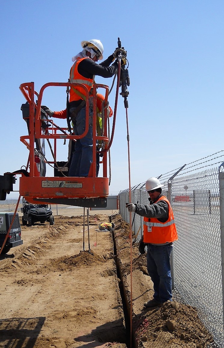
If I have heard it once, I have heard it a thousand times. The only legal ground rod must be installed a minimum of 8-foot in the ground. The length of rod and pipe electrodes is located at 250.52(A)(5) in the 2017 National Electric Code (NEC). See figures 1 and 2 for the section requirements.
However, what if I were to tell you this statement is not entirely true? What if there was an instance, or maybe two, where a 5-foot ground rod was acceptable? To find this elusive information, one must travel to the latter chapters of the NEC. To understand why this different length exists, you need to know the history.
Article 250 of the NEC — The 8 ft. Ground Rod
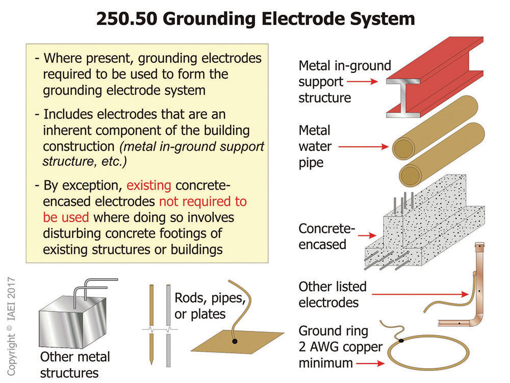
Article 250 contains general requirements for grounding and bonding of electrical installations. Sections 250.52(A)(1) through (A)(7) instruct users that all grounding electrodes present at each building or structure served shall be bonded together to form the grounding electrode system. Where none of these grounding electrodes exist, one or more of the grounding electrodes specified in 250.52(A)(4) through(A)(8) shall be installed and used (see figure 3).
Information on grounding electrodes can be found in 250.52. Within this section, various types of grounding electrodes are explained in detail. This article discusses the one located at 250.52(A)(5). See language below as well as figure 4.
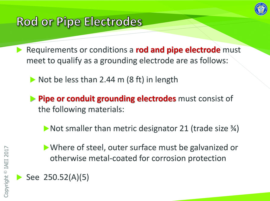
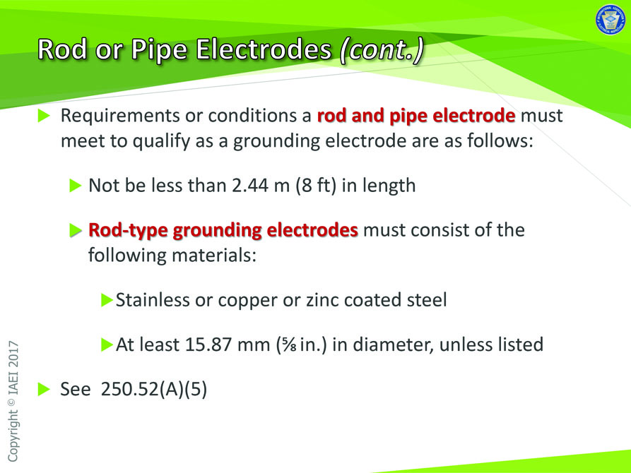
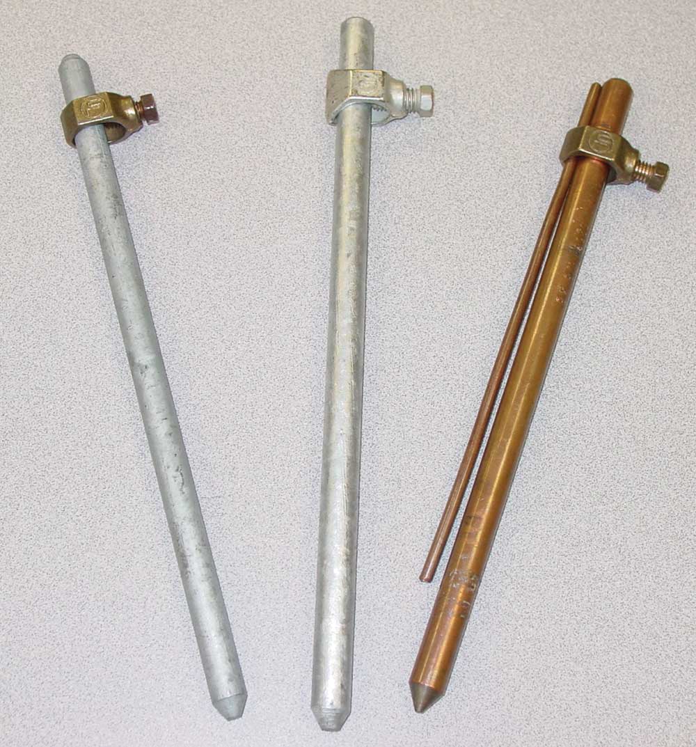
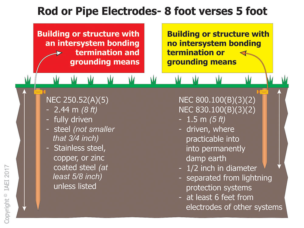
(5) Rod and Pipe Electrodes. Rod and pipe electrodes shall not be less than 2.44 m (8 ft) in length and shall consist of the following materials.
(a) Grounding electrodes of pipe or conduit shall not be smaller than metric designator 21 (trade size 3∕4) and, where of steel, shall have the outer surface galvanized or otherwise metal-coated for corrosion protection.
(b) Rod-type grounding electrodes of stainless steel and copper or zinc-coated steel shall be at least 15.87 mm (5∕8 in.) in diameter, unless listed. (2017 NEC)
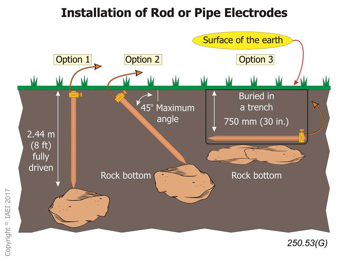
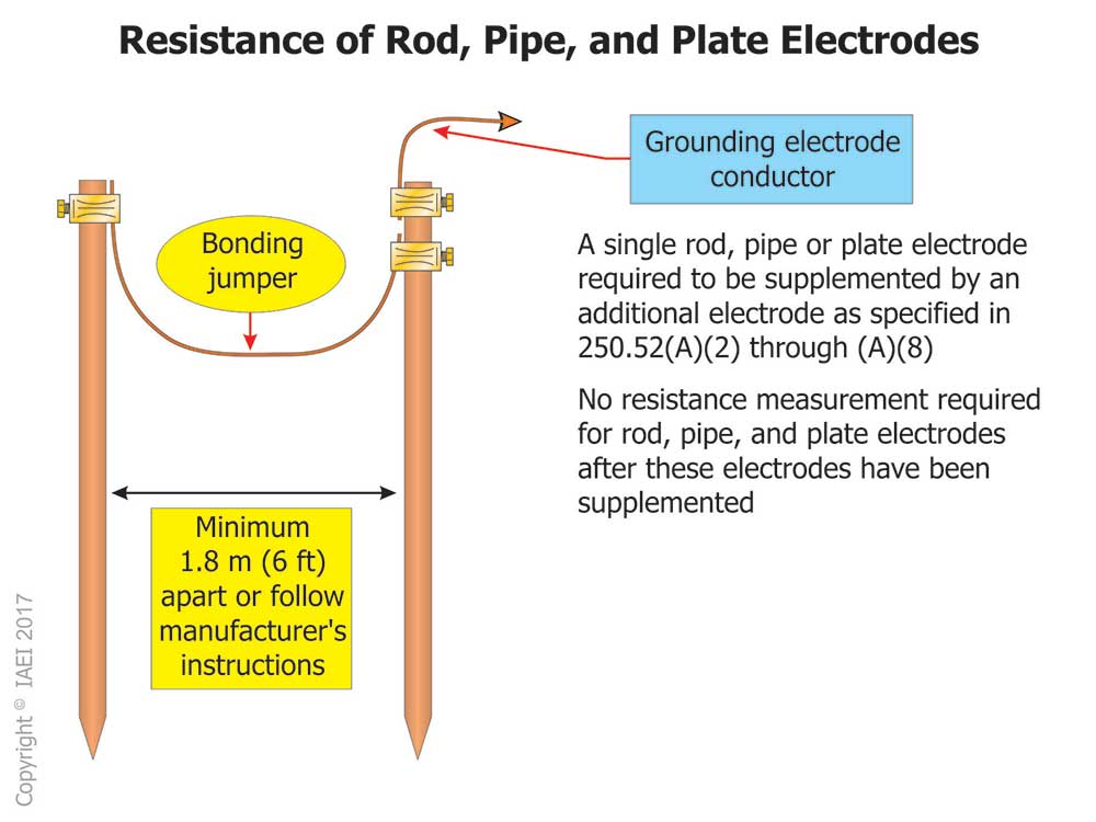
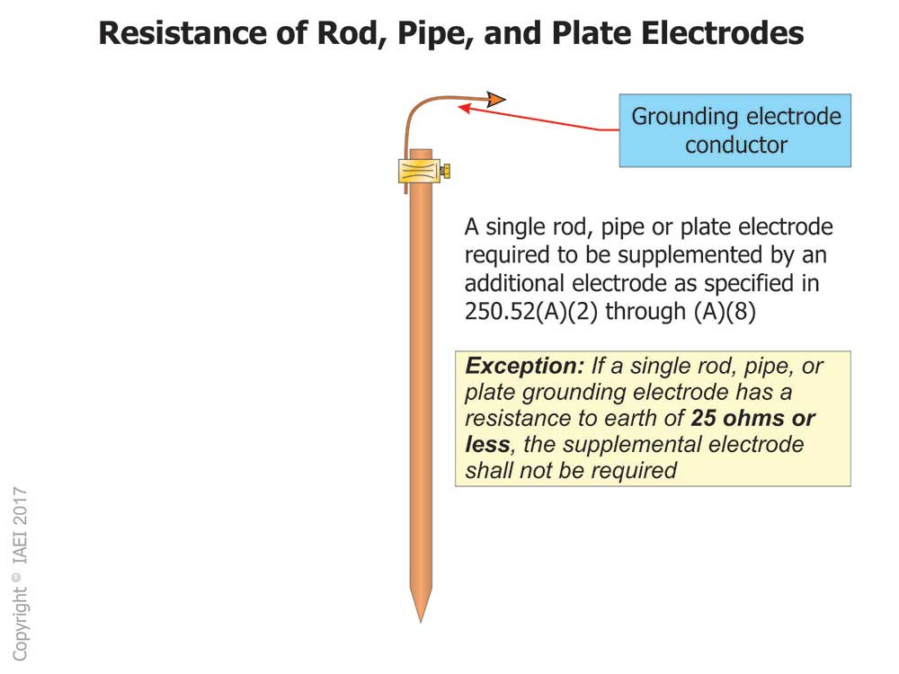
Other information specific to the installation of ground rods, such as installation and minimum resistance, can be found at Section 250.53(G) and 250.53(A)(2). See figures 5, 6 and 7 for additional information.
A Journey to Chapter 8 of the NEC — In search of the 5-foot Ground Rod
Now, here is the information that you have all been waiting for. Where do I find this “members only, highly classified” information where I can install a 5-foot ground rod? I am tired of driving 8-foot ground rods into the ground. This information could save years off my back and shoulders, not to mention money. Could it be that simple? Is there a place that allows me to install shorter ground rods for my electrical service?
The answer is “Yes, No, and Not so fast.” It is necessary to have a thorough understanding of the NEC to understand where these 5-foot ground rods are allowable and under what specific circumstances.
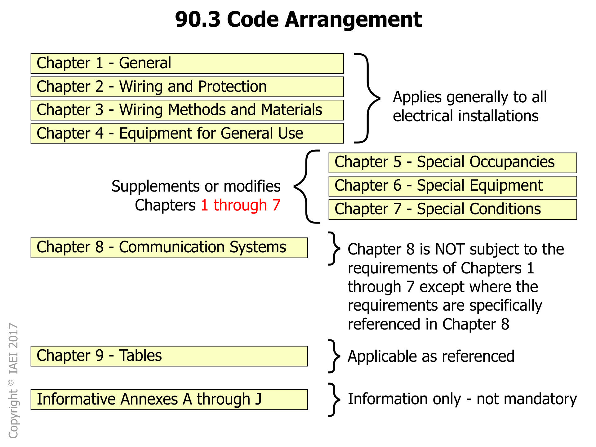
Article 800 is entitled, “Communication Circuits.” The purpose of this article is to cover various communication circuits and equipment. Section 800.2 defines a communication circuit as the circuit that extends voice, audio, video, data, interactive services, telegraph (except radio), outside wiring for fire alarm and burglar alarm from the communications utility to the customer’s communications equipment up to and including terminal equipment such as a telephone, fax machine, or answering machine. This article is not subject to the requirements of chapters 1 through 7 of the NEC except where the requirements are specifically referenced in chapter 8 (see figure 8).
The NEC is comprised of various parts; we need to next look in Part IV entitled “Grounding Methods.” Section 800.100 discusses cable and primary protector bonding and grounding. It states here that the primary protector and the metallic member(s) of the cable sheath shall be bonded or grounded as specified in 800.100(A) through 800.100(D).
If you are looking for the grounding electrode requirements, these are found in 800.100(B). This section states that the bonding conductor or grounding electrode conductor shall be connected in accordance with 800.100(B)(1), 800.100(B)(2), or 800.100(B)(3). Let’s look at the information contained in 800.100(B)(3).
(3) In Buildings or Structures Without an Intersystem Bonding Termination or Grounding Means. If the building or structure served has no intersystem bonding termination or grounding means, as described in 800.100(B)(2), the grounding electrode conductor shall be connected to either of the following:
(1) To any one of the individual grounding electrodes described in 250.52(A)(1), (A)(2), (A)(3), or (A)(4).
(2) If the building or structure served has no intersystem bonding termination or has no grounding means, as described in 800.100(B)(2) or (B)(3)(1), to any one of the individual grounding electrodes described in 250.52(A)(7) and (A)(8) or to a ground rod or pipe not less than 1.5 m (5 ft) in length and 12.7 mm (1∕2 in.) in diameter, driven, where practicable, into permanently damp earth and separated from lightning protection system conductors as covered in 800.53 and at least 1.8 m (6 ft) from electrodes of other systems. Steam, hot water pipes, or lightning protection system conductors shall not be employed as electrodes for protectors and grounded metallic members. (2017 NEC)
Wow, did you see it? One of the locations states the use and installation of a 5-foot ground rod. However, did you also see the specifics of this language? First, this is only allowable if the building or structure has no intersystem bonding termination or grounding means. In this instance, the use of a 5-foot ground rod is allowable.
The ground rod or pipe:
- shall not be less than 1.5 m (5 ft) in length and 12.7 mm (1/2 in.) in diameter;
- driven, where practicable, into permanently damp earth; and
- separated from lightning protection system conductors as covered in 800.53 and at least 1.8 m (6 ft) from electrodes of other systems.
The next usage of a 5-foot ground rod is found in Article 830, which covers network-powered broadband communications systems. These systems provide any combination of voice, audio, video, data, and interactive services through a network interface unit (NIU).
A typical basic system configuration includes a cable supplying power and broadband signal to a network interface unit that converts the broadband signal to the component signals. Typical cables are coaxial cable with both broadband signal and power on the center conductor, composite metallic cable with a coaxial member(s), or twisted pair members for the broadband signal and twisted-pair members for power, and composite optical fiber cable with a pair of conductors for power. Larger systems may also include network components such as amplifiers that require network power.
Article 830 contains various parts. In Part IV of Article 830, you will find grounding methods. The language here states that network interface units containing protectors, NIUs with metallic enclosures, primary protectors, and the metallic members of the network-powered broadband communications cable that are intended to be bonded or grounded shall be connected as specified in 830.100(A) through 830.100(D).
Information about the electrode is also located at 830.100(B). Let’s look at the language at 830.100(B)(3)(2).
(3) In Buildings or Structures Without an Intersystem Bonding Termination or Grounding Means.
If the building or structure served has no intersystem bonding termination or grounding means, as described in 830.100(B)(2), the grounding electrode conductor shall be connected to either of the following:
(1) To any one of the individual grounding electrodes described in 250.52(A)(1), (A)(2), (A)(3), or (A)(4).
(2) If the building or structure served has no intersystem bonding termination or has no grounding means, as described in 830.100(B)(2) or (B)(3)(1), to any one of the individual grounding electrodes described in 250.52(A)(7) and (A)(8), or to a ground rod or pipe not less than 1.5 m (5 ft) in length and 12.7 mm (1∕2 in.) in diameter, driven, where practicable, into permanently damp earth and separated from lightning conductors as covered in 800.53 and at least 1.8 m (6 ft) from electrodes of other systems. Steam, hot water pipes, or lightning protection system conductors shall not be employed as grounding electrodes for protectors, NIUs with integral protection, grounded metallic members, NIUs with metallic enclosures, and other equipment. (2017 NEC)
Wow, did you see it once again? This is the second location that states the use and installation of a 5-foot ground rod. But, did you also see the specifics of this language? First, this is only allowable if the building or structure has no intersystem bonding termination or grounding means. In this instance, the use of a 5-foot ground rod is allowable. The ground rod or pipe:
1. shall not be less than 1.5 m (5 ft) in length and 12.7 mm (1∕2 in.) in diameter;
2. driven, where practicable, into permanently damp earth; and
3. separated from lightning protection system conductors as covered in 800.53 and at least 1.8 m (6 ft) from electrodes of other systems.
Figure 9 attempts to show the requirements found in Article 250 and the requirements found in Article 800 and Article 830 as it pertains to the use of an 8-foot or a 5-foot ground rod.
The History of the 5-foot Ground Rod
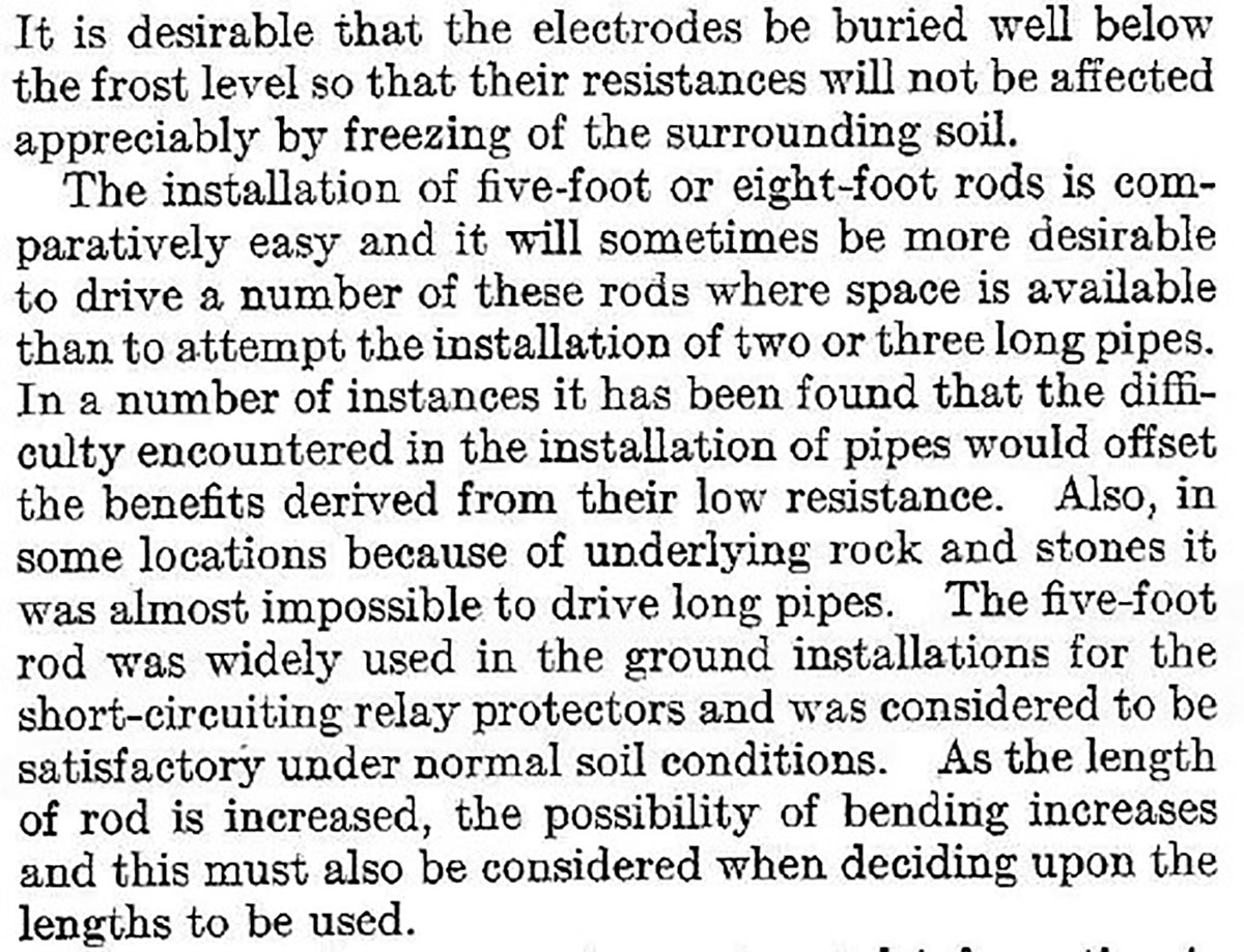
Rumor has it that the length of the 5-foot ground rod exists solely because that was the length of space in the backbend of Bell Telephone service vehicles. However, is that entirely true? Research provided to me by Mr. William McCoy of Telco Sales, Inc., who represents the Institute of Electrical and Electronic Engineers (IEEE), shows that there was scientific research into the usage of these rods. Research indicated that the wide-spread use of a 5-foot rod was used for the short-circuiting relay protectors and was considered to be satisfactory under normal soil conditions (see figure 10).
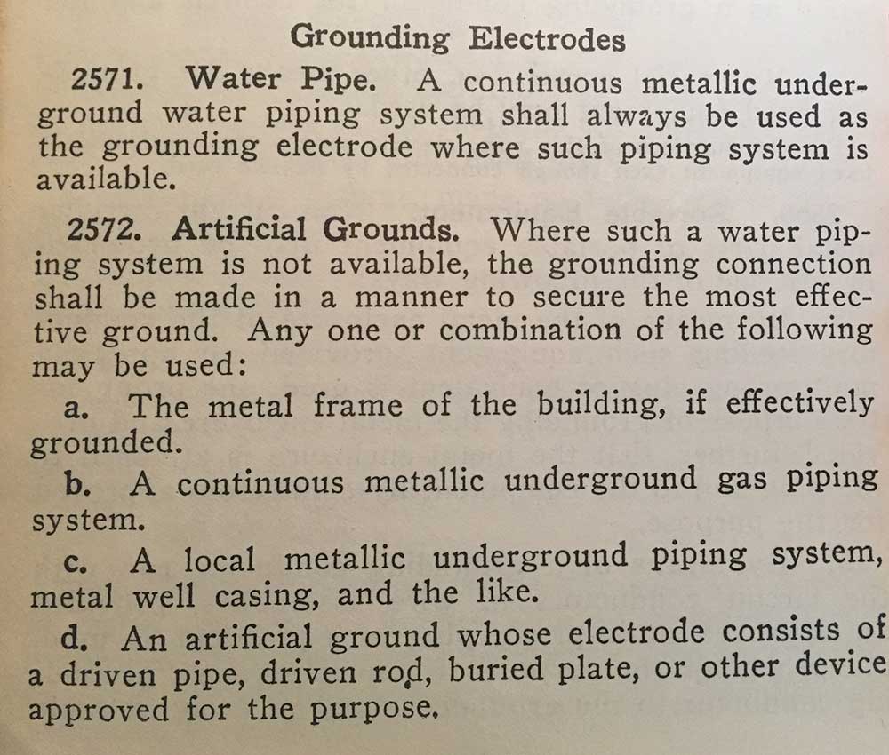
By researching the history of the NEC, I also found that that the first 8-foot length specified for a ground rod is found in the 1940 NEC. In the 1937 NEC, language existed for acceptable grounding electrodes at 2571 for water pipe and 2572 for artificial grounds. The text here referred to an artificial ground as one whose electrode consists of a driven pipe, driven rod, buried plate, or other device approved for the purpose. There was no further information given to the user of the Code as to the required length of this rod (see figure 11).
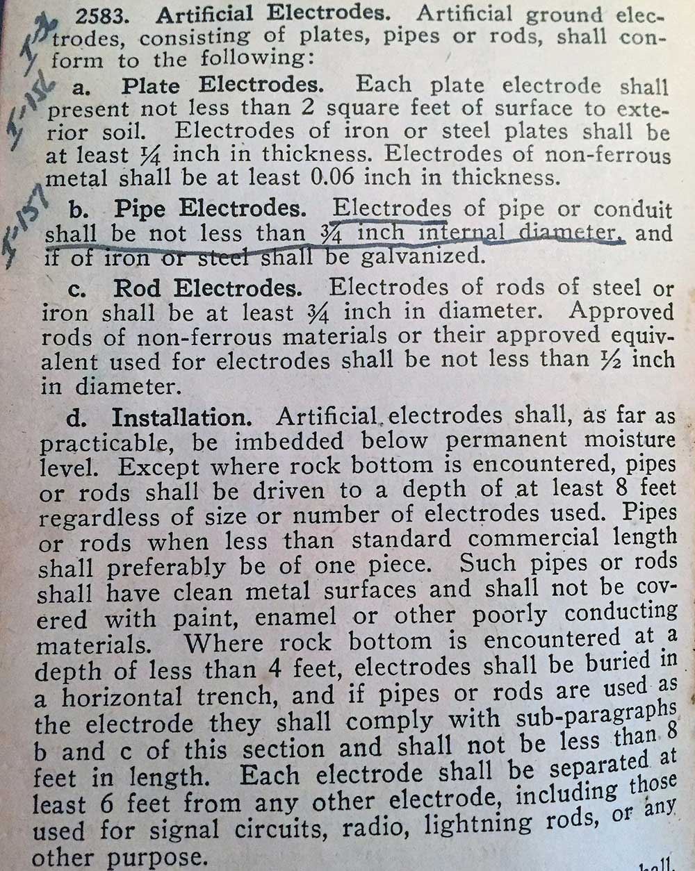
In the 1940 NEC, installation requirements were placed at 2583 for artificial electrodes. One of the stipulations is that the rod be driven to a depth of at least 8 feet regardless of size or number of electrodes used. See Figure 12 for further details.
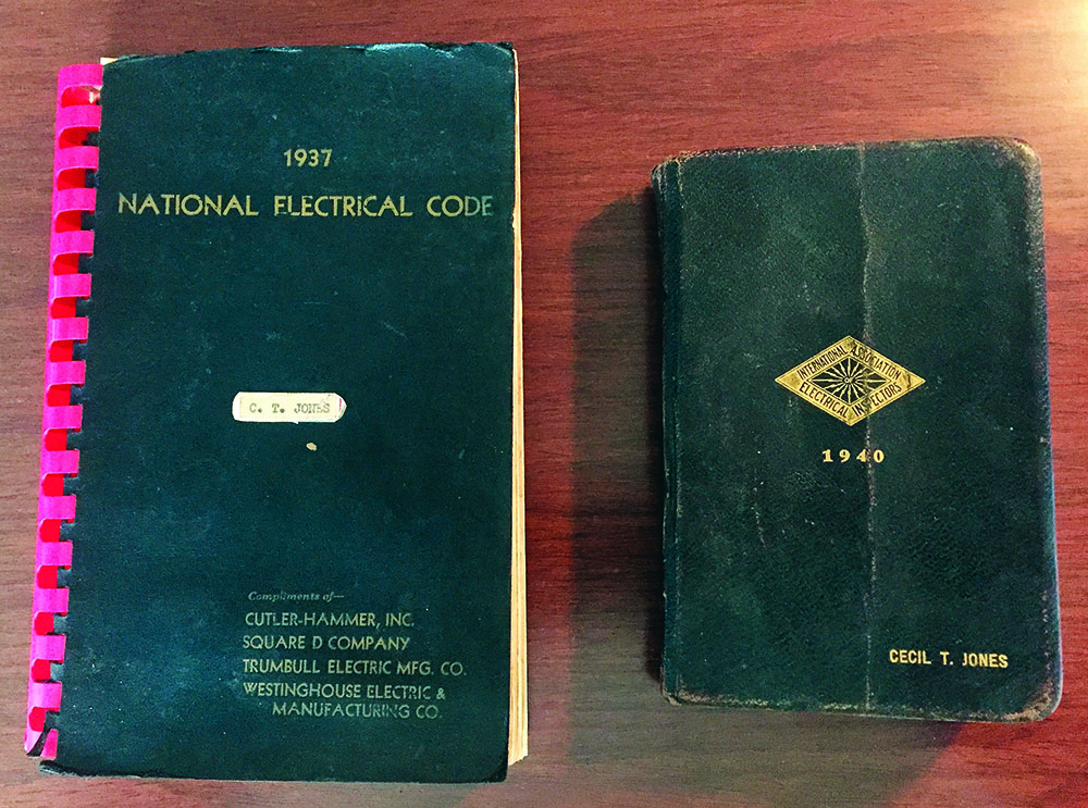
For you younger Code users out there, below is a photo of the 1937 and the 1940 NEC previously owned by Mr. Cecil T. Jones. It is interesting to see that the 1937 edition was of complements of electrical giants such as Cutler-Hammer, Inc., Square D Company, Trumbull Electric Manufacturing Company, and Westinghouse Electric and Manufacturing Company.
I am grateful to Mr. Jones as well as Mr. Philip H. Cox, a past CEO of the International Association of Electrical Inspectors (IAEI), for passing this history on to me for use in my career. Though the actions of these two gentlemen, information such as the history found above can be researched and brought to a new generation of electrical professionals. If we do not know, honor and appreciate our electrical history and the work of other pioneering individuals who went before us, we are doing dishonor to the electrical industry (see figure 13).
In Conclusion
During the first draft stage for the 2020 NEC, I submitted public inputs asking the code-making panel (CMP) responsible for Chapter 8 of the NEC to provide consistency by removing the 5-foot rod length and replacing it with the 8-foot length in the above mentioned two sections. I was somewhat shocked that in both cases the CMP-16 resolved or denied my request.
The 8-foot requirement is not specific to Article 250; there are two locations within Chapter 8 that allow a lesser rod length, but for very specific installations. Members of CMP-16 reached out to me and provided guidance and history for this reduced length. Many thanks to individuals such as Tom Moore, William McCoy, and Jeff Sargent for the tidbits of information that helped produce this article.
I hope that if you have ever had these same concerns, this article has provided insight into providing answers as to why the different lengths exist. This brings to mind a saying that is often thrown about in the electrical trade. “If you don’t like the answer in the NEC, look harder. There is bound to be an exception somewhere that will allow you to do it.”