All three elements of the fire triangle — oxygen, ignition source, and fuel — must be present simultaneously and in specific quantities for a fire or explosion to occur. Often, in hazardous (classified) locations, the electrical system will be the ignition source of the triangle. This article looks at five methods of protection to prevent electrical systems from becoming ignition sources in these locations.
Location of electrical equipment
This method involves designing the electrical system so that much or all of it is located outside the classified areas. An accurate area classification of the space and careful placement of the electrical equipment are required. Depending on the type of process and the facility involved, this option could eliminate some or all special electrical equipment; it would be cost effective and would result in safer installations. [NEC 500.5(A) Information Note and 505.5(A) Information Note 2].
However, this method cannot always be used since in some cases the electrical components must be installed within the operating process; for example, pumps, compressors, instrumentation.
In other cases, the electrical equipment can be located to an area less likely to contain ignitible concentrations. Relocating equipment a relatively short distance away often has a major impact on safety and equipment requirements; the relocation can also result in decreased costs.
Figures 1, 2 and 3 demonstrate this protection method by relocating the luminaires. In figure 1, the luminaires are located within Division 1. In figure 2, the luminaires have been moved to Division 2. Then in figure 3, they have been installed outside Class 1, Division 1 or 2 locations. An accurate area classification and careful placement of electrical devices will always reduce both cost and risk of ignition in Class I locations.
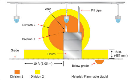
Figure 1. Luminaires installed in Class I, Division 1 locations must be suitable for that location.
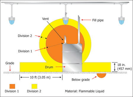
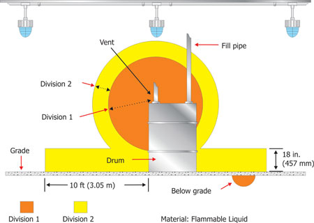
Figure 3. Luminaires installed outside a Class I, Division 1 or 2 location can be suitable for general use.
The principles are exactly the same for space classified using NEC 505, the Zone system. As in the Division system, a relatively minor relocation of many electrical devices could result in the use of ordinary location equipment. As the equipment location is moved from Zone 0 to Zone 2, the number of permitted protection techniques increases. This provides more flexibility, a decrease in cost, and a safer installation.
However, in Zone 0 spaces, Article 505 allows only electrical equipment that is protected by the intrinsic safety, or encapsulation techniques. This stipulation prohibits many electrical functions from taking place in that space.
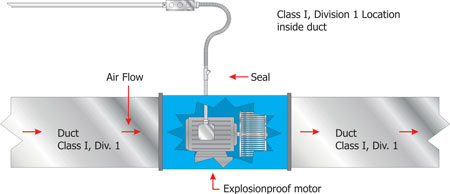
Figure 4. Exhaust duct with the electric fan motor installed inside the duct (hazardous location)
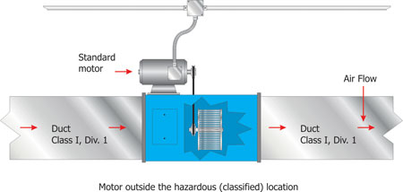
With accurate area classification, on the other hand, much of the electrical equipment — lighting, alarm devices, security devices and communication devices — can be relocated to less classified or unclassified locations in many facilities. One example involves the location of the exhaust fan motor when ventilation is provided in hazardous (classified) locations. NEC 500.5(B)(1) Information Note 2, item 5 and 505.5(B)(1) Information Note 2 identify the “interior of an exhaust duct that is used to vent ignitible concentrations of gases or vapors” as a Division 1 or Zone 0 location. Figure 4 shows the exhaust fan motor located inside the duct, which is permitted in a Division system if the fan is explosionproof. In almost all applications, the motor could be located outside the duct in a Division 2 or unclassified location as shown in figure 5, and would achieve the same purpose using an ordinary location motor. With limited protection techniques permitted in Zone 0, installing the motor outside the duct may be the only practical option.
Containment of combustible materials
Controlling fugitive emissions
While the Environmental Protection Agency regulations address release of particles into the atmosphere in a different way than area classification, any control of release will have an impact on the area classification. This is not to say Division 1, Zone 0 or Zone 1 areas do not exist, but large-scale areas are not as common as they were in the past. It is no longer environmentally acceptable to vent waste products from a process, which, in some industries, could include flammable and combustible vapors into the atmosphere.
These EPA requirements have led to greater control of fugitive emissions, defined in American Petroleum Institute (API) Recommended Practice (RP) 500, Section 3.2.24 as “continuous flammable gas and vapor releases that are relatively small compared to releases due to equipment failures. These releases occur during normal operations of closed systems from components such as pump seals, valve packing and flange gaskets.”
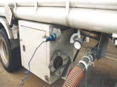
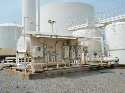
NFPA 30, Flammable and Combustible Liquids Code defines fugitive emissions as both continuous and intermittent releases and includes additional components that may be the source of release. Today vapor recovery is provided with many fill operations involving flammable or combustible liquids. Consequently, a much smaller volume of flammable or combustible vapor is released into the atmosphere. A common example of vapor recovery is used with gasoline delivery (see photo 1). As the gasoline tanks are filled, the vapors located above the liquid level in the tank are recovered into the tanker trucks, rather than being forced out the tank vents. These recovered vapors are then taken back to the bulk storage facilities, where vapor recovery is also provided (see photo 2).
Adoption and enforcement of EPA regulations could have a different impact on area classifications from state to state, region to region and even from industry to industry since the goal of those regulations is environmental not prevention of ignitible concentrations as it relates to electrical installations. The National Electrical Code is used both in the U.S. and in other countries, some of which may have different regulations and may not have any environmental regulations.
Controlling the fuel side of the fire triangle
For Class II and Class III locations, dust collection systems and housekeeping have a major affect on area classification through the containment of combustible or ignitible material. These concepts provide health benefits to employees, greater mechanical life for moving equipment, and minimize overheating of electrical equipment that would otherwise be covered with layers of dust or fibers.
In order to realize the benefit of dust collection and housekeeping and also to use this method of protection by controlling the fuel side of the fire triangle, the installation must comply with the standards and recommended practices for the specific industry (see sidebar).
Section 3-3.2 of NFPA 499 indicates that areas designated as unclassified based on dust collection should be required to include adequate safeguards and warnings against failure. This might include some method to turn dust-producing equipment off when dust collection equipment is inoperable. Photo 3 shows a dust collection system that limits the dust cloud in this operation and, in turn, minimizes the dust layering. That in combination with housekeeping can greatly limit the amount of special electrical equipment needed for this operation.
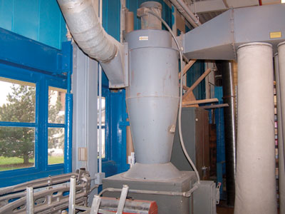
Photo 3. Typical dust collection system (equipment shown inside of structure)
In many facilities, classified areas can be limited by providing closed storage vessels and transporting flammable and combustible materials through well-maintained closed piping systems. NFPA 497 and 499 both recognize these situations as unclassified areas. Special electrical equipment in the closed systems might be limited to instrumentation devices.
Containing with solid partitions
Separating hazardous locations with walls, enclosed vaults, or other solid partitions is another means to contain combustible materials and limit area classification. Containing the flammable or combustible materials is possible with Class I, Class II and Class III location materials. Since dusts and fibers/flyings are solid materials rather than gas, they may be easier to contain by separation. Where separation of smaller hazardous areas within a larger facility is used as a method of protection, extreme caution should be used to completely close off the classified spaces. All openings and penetrations through the separation must be considered for possible releases of the combustible materials. Figure 6 shows an example where an unpierced wall on one side of a structure that contains a Class I point of release ends the classified space. The opposite wall of the structure has openings that require the classified area to extend outside the structure.
Figure 7 shows a structure containing a Class II point of release. Walls on two sides of a structure are unpierced and an additional wall has an infrequently used self-closing door. The classified space does not extend beyond any of these walls. The other wall of the structure has a frequently opened door that requires the classified area to extend outside the structure.
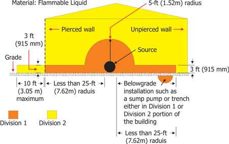
Figure 6. Extent of classified locations can be extended due to openings in walls or structures
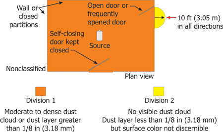
Figure 7. The classified space does not extend beyond the walls
Ventilation
NEC 500.5 recognizes the affect of ventilation in the area classification process. Adequate ventilation is defined in Section 1-3 of NFPA 497 as “a ventilation rate that affords either 6 air changes per hour, or 1 cubic feet per minute (cfm) per square foot of floor area, or other similar criteria that prevent the accumulation of significant quantities of vapor-air concentrations from exceeding 25 percent of the lower flammable limit.”
It should be recognized that the air change information included in this definition is not very specific. If the air changes noted do not limit the concentration of vapors to 25 percent of the lower flammable limit, the area classification should not be adjusted. In many cases where limited releases are occurring, those air change rates will likely provide adequate ventilation. In other cases where larger releases are expected, it may be determined that those air change rates are not sufficient to change the area classification. A review of the specific occupancy code, standard or recommended practice is advised prior to adjusting the area classification based on 6 air changes per hour. Some standards are very specific about the location of the exhaust and supply ducts, depending on the vapor density of the material involved. Some require product shutdown upon failure of ventilation. Others require gas detection systems to be interconnected with shutdown of a process. In every case, the code, standard or recommended practice for the facility should be considered prior to adjusting area classification based on ventilation.
Section 3-3.2 of NFPA 497 also indicates that outside installations and installations within open or partially open structures may be considered to have adequate ventilation and be classed “unclassified.” Nevertheless, a review of many of the occupancy documents will result in those spaces being classified. Section 1-2.3 of NFPA 497 indicates the occupancy document is a recommended practice and is intended as a guide that should be applied with sound engineering judgment. For example, when the information is used within its context and all of the parameters are considered, some outside installations will result in unclassified areas and others will result in classified areas. When it is determined that adequate ventilation has been provided, the specific standard for the industry or material involved will provide the guideline for the impact of ventilation on the area classification.
Great care should be used when the classification of a space and type of electrical equipment is changed based on the fact that ventilation is provided. Ventilation is required and may be provided in many facilities for reasons other than reducing the area classification. NFPA 500, Section 38.7 addresses attic ventilation; Section 54.4 requires ventilation of elevator rooms to maintain required temperatures during fire fighter service operations; Chapter 49 requires all rooms and occupied spaces in buildings to be ventilated; Section 49.2.2.1 requires various types of occupancies to conform to ASHRAE 62, Ventilation for Acceptable Air Quality. ASHRAE Standards provide ventilation requirements for spaces intended for human occupancy and specify minimum and recommended ventilation air quantities for preservation of the occupant’s health, safety and well-being.
NFPA 91, Standard for Exhaust Systems for Air Conveying of Vapors, Gases, Mists and Noncombustible Particulate Solids provides some general requirements for design and construction of exhaust systems which may be modified by other applicable standards. Systems that comply with this standard are limited to conveying flammables that are not more than 25 percent of the lower flammable limit unless they also meet the requirements of NFPA 69, Standard on Explosion Prevention Systems. Under normal conditions, fire detection and alarm systems are not permitted to shut down these air-moving devices.
Grounding and bonding requirements
Grounding is required for the protection of electrical installations, which, in turn, protect the buildings or structures in which the electrical systems are installed. Persons and animals that may come into contact with the electrical system, or are in these buildings or structures, are also protected if the grounding system is installed and maintained properly. The National Electrical Code does not imply that grounding is the only method that can be used for the protection of electrical installations, people or animals. Insulation, isolation and guarding are also suitable alternatives under certain conditions. Grounding of specific equipment is covered in several articles of the NEC. The scope and general requirements for grounding and bonding are contained in NEC 250.4. Included are the grounding and bonding performance requirements for grounded systems and ungrounded systems.
The Code places some special requirements for grounding and bonding in hazardous (classified) locations. These requirements can be found in NEC 501.30 for Class I locations; in 502.30 for Class II locations; and in 503.30 for Class III locations. For Class I, Zone 0, 1 and 2 hazardous (classified) locations, see NEC 505.25. Since this protection method is far more detailed than can be covered in this article, it is recommended that the reader refer to these Code sections, and to chapter 2 of Hazardous Locations, and to Soares Book on Grounding and Bonding, both books published by IAEI.
System shutdown and alarms
Methods of protection for hazardous locations often include engineered designs that incorporate specific ventilation systems, interlocks, and alarms. The basic objective of these systems is to minimize or remove one or more of the components of the fire triangle. Where movement of air is applied, the possibility of ignitible concentrations of hazardous atmospheres is reduced. A couple of examples are found in NEC 511.
Section 511.3(C)(1) indicates that the area 450 mm (18 in) above the floor in a commercial garage is unclassified if there is mechanical ventilation that provides a minimum of 4 air changes per hour or 1 cubic foot per minute of exchanged air across the entire floor area, and if the exhausted air is taken from a point within 0.3 m (12 in.) of the floor.
Section 511.3(C)(3) also indicates that lubrication service facilities — consisting of pit, belowgrade work area or subfloor work area — are classified according to whether ventilation is provided. If ventilation is not provided, any pit or subfloor work area is classified as Class I, Division 1 up to the floor level. If mechanical ventilation provides a minimum of 6 air changes per hour, the classification is Class 1, Division 2. There is no transfer of any Class 1 liquids, pits or work areas below grade level that are provided with not less than 0.3 m3/minute/m2 (1 cfm/ft2) of exhaust ventilation. The exhausted air must be taken from a point within 300 mm (12 in.) of the floor level of the pit or subfloor work area. Note that there are no requirements for interlocks or alarms in these Code rules; however, the Code does require that the exhaust ventilation for the pit of belowgrade work areas be operational at all times when the building is occupied or when vehicles are parked over the pit or belowgrade work area(s). A mechanical engineer can usually provide a design and documentation verifying to approving authorities that the require air movement or exhaust has been provided to allow the area to be considered unclassified. It is important that the occupant and operators of the facility understand the importance of these ventilation systems as they relate to building and personnel safety.
Another method of protection can be provided by a combination of gas detection system and air changes, which are generally specific to the project or location. An example would be a design that might include an exhaust system that provides a minimum number of air changes in the appropriate location, depending on the properties (vapor density) of the gas involved. If the gas is heavier-than-air, exhausted air will generally be taken from locations close to the floor or grade level. If the gas is lighter-than-air, exhausted air is usually taken from locations near the highest point of the facility or location. Interlock systems are often used to provide warnings by audible and visual alarms, or both in combination, to warn qualified operators that the method or protection is not operational. In addition to interlocks for personnel warning systems, there could be a shutdown interlock system that removes power from the electrical system in the area where the exhaust or ventilation system has failed or is not operating. This can be accomplished by using shunt-trip breakers and contactors that are interlocked with the specific exhaust or ventilation system. Usually any necessary electrical circuits or systems, such as emergency lighting equipment of exit lighting are provided in these areas, but they are installed using the appropriate protection technique for the area so they remain operational.
Sometimes gas detection systems are used as the primary protection method and are part of a system design that includes not only detection of ignitible concentrations but also works cooperatively with an exhaust or ventilation system and a shunt-trip interlocking system for system shutdown. These systems are usually equipped with early warning audible and visual alarms to warn facility personnel or operators of ventilation or exhaust systems failure and ignitible mixture accumulations that are increasing to hazardous (explosive) levels. These types of engineered systems or designs are generally limited to applications in industrial facilities or to installations where there are qualified persons who are familiar with the operation and servicing of these safety systems. Even where these multilevel methods of protection are employed, safety depends on qualified persons that can respond appropriately if any necessary component of the designed system were to fail or become inoperative.
Documentation
The Code requires documentation of areas designated as hazardous (classified) locations as provided in 500.4(A). Although this section only calls for the hazardous areas to be designated, often the documentation provided by engineering and design teams includes how the area was classified, together with information about associated exhaust or ventilation systems and interlocked systems that allow for definitive delimitation of the hazardous locations. The documentation should also include the hazardous area classification that can result from ventilation system failure. As indicated in NEC 500.4(A), the documentation is required to be available to those authorized to design, install, inspect, maintain, or operate electrical equipment at those locations. It is important that an adequately designed protection system be properly operated and monitored to maintain minimum levels of safety in hazardous locations.
Dust Collecting and Housekeeping
A few of the standards and recommended practices that include specific requirements related to dust collection and housekeeping are:
- NFPA 36. Standard for Solvent Extraction Plants
- NFPA 61. Standard for the Prevention of Fires and Dust Explosions in Agricultural and Food Products Facilities
- NFPA 120. Standard for Coal Preparation Plants
- NFPA 480. Standard for the Storage, Handling, and Processing of Magnesium Solids and Powders
- NFPA 481. Standard for the Production, Processing, Handling, and Storage of Titanium
- NFPA 482. Standard for the Production, Processing, Handling, and Storage of Zirconium
- NFPA 499. Recommended Practice for the Classification of Combustible Dusts and of Hazardous (Classified) Locations for Electrical Installations in Chemical Process Areas
- NFPA 651. Standard for the Machining and Finishing of Aluminum and the Production and Handling of Aluminum Powder
- NFPA 654. Standard for the Prevention of Fire and Dust Explosions from the Manufacturing, Processing, and Handling of Combustible Particulate Solids
- NFPA 655. Standard for the Prevention of Sulfur Fires and Explosions
- NFPA 664. Standard for the Prevention of Fires and Explosions in Wood Processing and Woodworking Facilities
Ventilation requirements for codes & standards
NFPA 30, Flammable & Combustible Liquids Code requires all atmospheric storage tanks that contain flammable or combustible liquids to be adequately vented to prevent the development of vacuum or pressure conditions that might distort the tank or exceed the design pressure of the tank. This adequate vent of the tank is not going to provide ventilation that is adequate to prevent the accumulation of vapor-air concentrations from exceeding 25 percent of the lower flammable limit. This code includes ventilation requirements in sections 2.2.7.5 for vaults that contain tanks storing Class I liquids; 2.3.4.4 for tank buildings; 4.4.2.7 for inside liquid storage areas; 4.6.3.4 for hazardous materials storage lockers; and 5.3.4.1 for enclosed processing areas handling or using Class I, Class II or Class III liquids above their flash point. With the ventilation requirements met, some of these spaces are Class I Division or Zone 1 and others are Class I, Division or Zone 2.
NFPA 57, Liquefied Natural Gas (LNG) Vehicular Fuel Systems Code requires buildings with indoor fueling to provide continuous mechanical ventilation or a mechanical ventilation system that is activated by a continuous gas monitoring system, which activates the ventilation system when a gas concentration of one-fifth of the lower flammable limit is present. Both of these ventilation options are required to shut down the fuel system if the ventilation system fails. The ventilation rate shall not be less than one cubic foot per minute per 12 cubic feet of room volume. When adequate ventilation is provided, some locations are classed Class I, Group D, Division or Zone 1 and others Class I, Group D, Division or Zone 2.
Additional requirements are provided for commercial marine vessels operating on LNG.
NFPA 120, Standard for Coal Preparation Plants allows adequate ventilation to reduce area classification from Class I, Division 2 where methane can reach ignitible concentrations to unclassified. Any equipment that is needed to restore the facility to a safe condition such as lighting, ventilation, and sump pumps must be installed based on Class I, Division 1 requirements. Additional gas monitoring and shutdown provisions are also required when area classification is reduced because of ventilation.
NFPA 409, Standard on Aircraft Hangars permits mechanical ventilation for vapor removal in accordance with NFPA 91, Standard for Exhaust Systems for Air Conveying of materials.
NFPA 651, Standard for the Machining and Finishing of Aluminum and the Production and Handling of Aluminum Powders includes a reference to the ventilation requirements in NFPA 30, where aluminum dusts or powders are present in the same area with flammable or combustible solvents.
NFPA 820, Standard for Fire Protection in Wastewater Treatment and Collection Facilities indicates that ventilation rates used in that standard are based on air changes per hour and are calculated by using 100 percent outside air for the supply air that is exhausted. Air changes are calculated using the maximum aggregate volume of the space to be ventilated under normal conditions. Ventilation is not required, but is permitted if designers and owners desire area classification reduction. Ventilation systems used to reduce area classification in this standard are required to have both supply and exhaust fans, a means to provide power from an alternate power source, a power loss alarm on the primary power source, and include a variety of ventilation rates depending on what location or function in the collection and treatment process is involved and area classification that is desired to be achieved. All continuous ventilation systems installed for these facilities are required to include flow detection devices which are connected to an alarm signaling system and include both visual and audible alarms located in specific locations.
NFPA 853, Standard for Installation of Stationary Fuel Cell Power Plants requires mechanical ventilation of rooms where fuel cell power plants are located. The exhaust rate must be at least 1 cfm per square foot of floor area for the room and not less than 150 cfm of total floor area. That standard also requires the ventilation to be interlocked so that the unit will be shut down upon loss of ventilation.
Excerpted from Hazardous Locations, Second Edition, International Association of Electrical Inspectors, Richardson, Texas. Updated to NEC-2011.



Find Us on Socials