
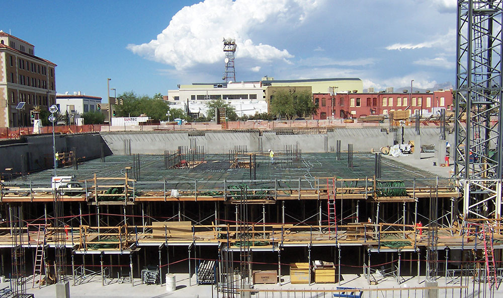
This article will take you through the electrical construction of a nine-story high-rise structure with parking at three floors down and four floors up. We will start at the bottom with the concrete-encased electrode (Ufer) and go all the way up to the first cup of coffee. We will show you both the complexity of the service and the simplicity of the receptacles. This installation was originally reviewed per the 2011 National Electrical Code (NEC) and other applicable codes. I’ve also checked the 2011 requirements against the 2020 edition and made any updates as necessary.
Grounding Considerations
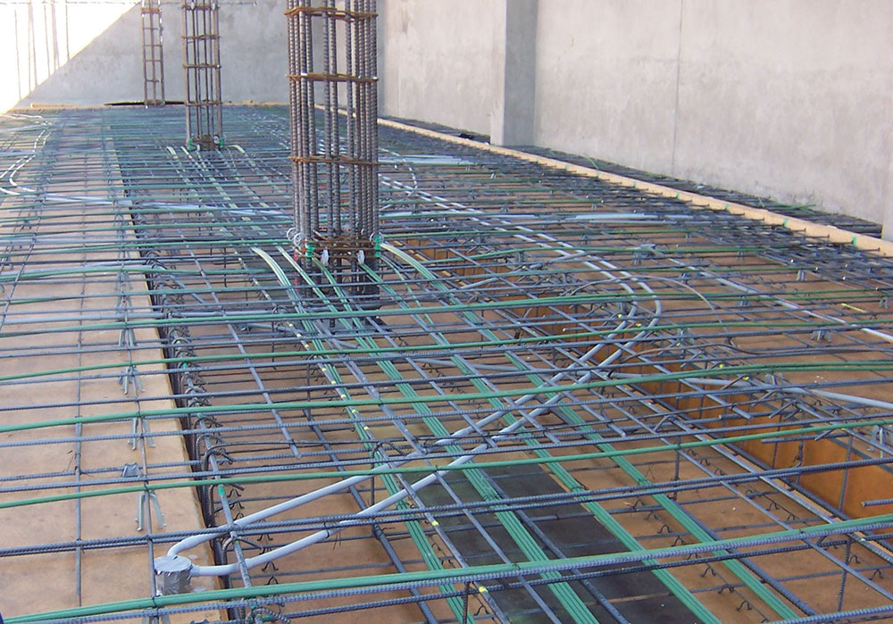
Let us start with the grounding electrode conductor. For this structure, the engineer chose to install a 3/0 AWG conductor (NEC 250.66) around the entire perimeter down in the bottom under the foundation slab (NEC 250.64). The conductor was bonded to the rebar (NEC 250.50 & 250.52) and was placed on top of a moisture retention layer of a concrete slurry seal. This is not to be confused with a ground ring [NEC 250.52(4)], which is to be in direct contact with the earth. This conductor was then installed up to the service located on the ground floor and continued up to the roof for the common grounding electrode conductor [NEC 250.30(6)(a)].
On each floor, there are exothermic welds and incorporated ground bus bars for two electric rooms and two data communication rooms. On the third floor, there are connections for the data server room and the battery backup system. By using this grounding and bonding riser system, we can connect all of the metallic piping and exposed structural steel required to be bonded by NEC 250.104. The generator and load bank are also connected to the common grounding electrode. The lightning protection system was connected to the common grounding electrode conductor via the exothermic welding process.
Size 3/0 AWG braided copper conductors are used for the connections as required by NEC 250.106. These also are installed up to the roof for connection to the air terminals. While checking this particular installation, remember to verify that all are continued up to the intended locations. All of these runs were interwoven through the rebar within the building structure and not in raceways.
Floor Layout and Construction Concerns
As the floors are being constructed, close attention is required to the layout locations for the electrical equipment, devices, and proposed conduit routing. First, verify the separation of power circuits and emergency circuits as required by NEC 700.10.
Another area of concern is the placement of junction boxes. Junction boxes may be used for splice points, floor receptacles, lighting outlets, as well as for data and communications. On this project, listed raceway connections from electrical nonmetallic tubing (ENT) to conduit fittings embedded in these slabs were used. Note that per NEC 362.6, ENT and associated fittings shall be listed; see Electrical Nonmetallic Tubing Fittings (FKKY) on UL Product iQ (UL.com/piq).
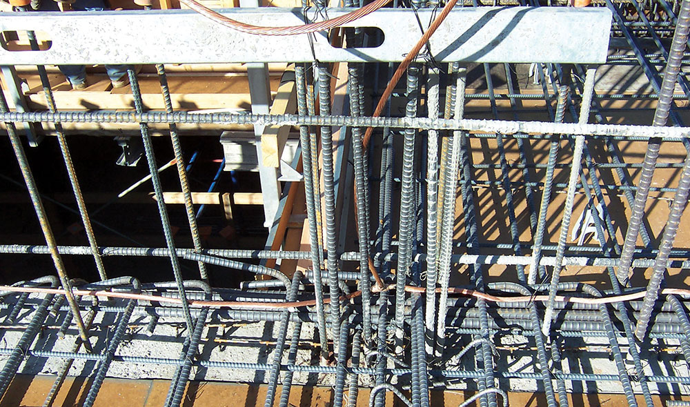
This building was constructed with post-tension slabs; therefore, critical consideration must be given to the location of raceways, cables, and electrical boxes (see Post Tensioning Institute (PTI) Manual and the architectural and structural pages of the plans). There is the crush zone at 18 in. out from the point of tensioning at a 45-degree angle where no electrical device should be placed (PTI Manual, 10.2.1/Fig. 10-1). The installer needs to maintain two feet on each side of pour joints with rigid steel raceways to prevent breakage. The manual also recommended 6-in. spacing from the tendon cables for placement of electrical system components.
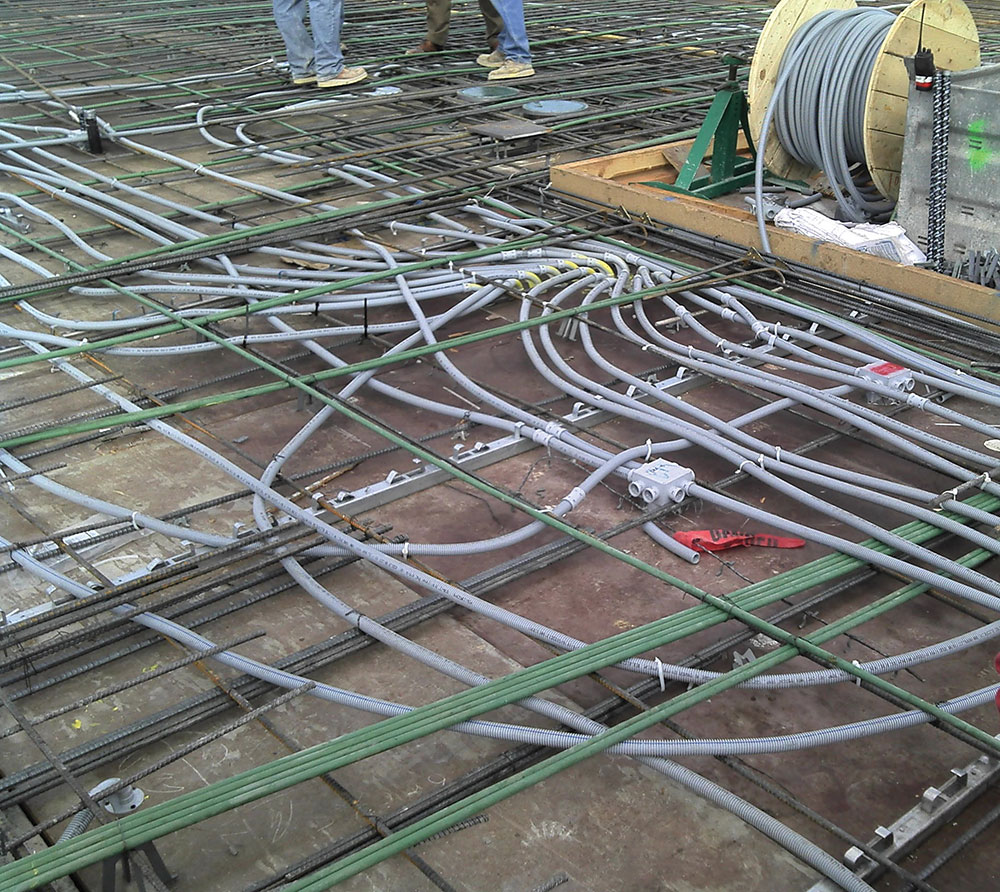
On this particular job, the electrical contractor started out with PVC and then changed to ENT. The difficulties with the PVC were in the routing. The slab thickness was only 8 in. and the structural engineer had limitations of conduits being placed in the slabs. The raceways had to be in the middle two-thirds of the pour as directed by the Architectural and Structural Plans. ENT was able to be navigated through the steel with less difficulty.
NEC 352.26 and 362.26 limit the number of degrees in a conduit run to 360°. The number of runs allowed in the area of the structural web or beam is limited due to the structural integrity (refer to structural drawings and specifications). To alleviate this problem, ENT raceways were brought up into the underfloor at each level as necessary. Additional floor-to-floor sleeves were added to bring the data cables back down to the designated communication rooms. The underfloor was a pressurized plenum space, and the ENT had to be encased as per the requirements of NEC 300.22. Where the sleeves and block-outs for the buss ducts were placed, the location of post-tensioning cables and rebar steel had to be taken into consideration.
During these stages, the splicing and connections of the grounding electrode conductor, the bonding conductors, and the lightning protection conductors should be carefully inspected.
Power Distribution System
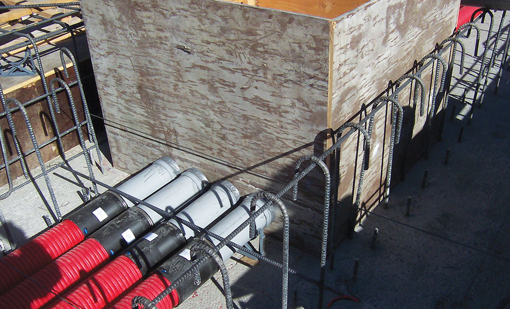
The next large scope of this project was the installation of the main power distribution system. It was decided to bring the utility power into two PMEs (pad-mounted equipment). The utility required their raceways to have concrete encasement. From the PMEs, 4-inch PVC conduits were extended to the three transformers, one 500 kVA and two 2500 kVA. From the transformer’s secondary to the service equipment sections (SES), sixteen 4-inch PVC conduits were needed.
A primary concrete enclosure that crossed the building from one side to the other was constructed in two stages. At one area of the primary concrete enclosure, thirty-two 4-inch PVC conduits were installed. The first concrete pour was framed below the main floor — before the main floor was poured — with rebar extending up and into the main floor rebar steel for interconnection when the main floor concrete was installed.
After all raceways were installed and racked in place, the concrete junction box forms were constructed. The boxes were sized in accordance with the dimensions from NEC 314.28(A)(2). These boxes were used to provide the conductor routing of the two 4000-amp SESs, each with the sixteen sets of 500-kcmil copper conductors. The main floor was then poured while encasing all the primary raceways. In essence, this “trench” was hung from the first floor. Also included in this “trench” was the service-entrance run for the fire pump controller that is required to be outside the building or to be concrete-encased. Feeders for other items, such as those for the generator, were placed under or within the building slab.
It is recommended to watch your concrete guys; they sometimes get in a hurry for their pours. The project experienced a big OOPS in the “trench” pouring phase. It was designed to be installed as a two-pour application to allow for air in the conduits and settling. Instead, they poured it all at one time, and the thirty-two 4-inch PVC conduits floated up, and one full layer was exposed above the finished floor. Fortunately, the transformer vault had a high ceiling, which allowed for a raised 6-inch floor to cover the concrete contractor’s mistake.
For termination to the two 4000-amp SESs, the plans noted a requirement for cable bracing of the conductors for connections. Once we leave the main SESs, we have multiple methods employed.
Conduit raceways were installed with proper support methods as indicated by the type of raceway. Supporting of conductors in vertical raceways also needs attention. Use NEC Table 300.19(A) to determine at what lengths to support your conductors based on sizes.
The busways provided for an interesting means of power distribution. Let’s follow the path. To begin with, nine busways leave the SESs. Bus duct supports are required at 5 ft (1.5 m) on center unless otherwise designed and marked per NEC 368.30. Keep in mind that this is the minimum required for support. Different situations such as a change in direction or passing through walls or floors may dictate more supports as necessary. These bus ducts then went to a variety of connections. Most were through underfloor connections to the panelboards. The main SESs connections exited from the top of the sections. There are four automatic transfer switches. We will cover those later in the generator distribution systems.
Nine busway risers travel up from the main floor toward the roof. On one floor, two of the busway sections passed behind a wall, so an access door was added as required by NEC 368.10(B) &(C)(1). There is one busway for the parking garage and elevators. All of these busways throughout the building provide power for lighting, receptacles, the physical plant, emergency systems, and power for the 2N dual-fed uninterruptable power source (UPS)/data center system. When the bus ducts are passing through the floors, a 4-inch curb is required per NEC 368.10(C)(2)(b).
The designer and inspector should pay attention to the overcurrent protection in NEC 368.17(C). Verify means for disconnecting operations of buss plug disconnects where mounted out of reach, such as ropes, chains, or sticks. For this manufacturer, the duct-splice connection torque settings were made simple by using breakaway bolts.
There is also an 800-amp SES installed for future tenant spaces and for the rooftop photovoltaic system. This SES has the ability for the bottom and top raceway entries. These locations fall under NEC 408.3(A)(2), “…only those conductors that are intended for the termination in a vertical section of a switchboard shall be located in that section.”
Also, check working and dedicated spaces for compliance with NEC 110.26(A) – (F). We will go over labeling when we get to our final inspection and floor electrical rooms.
Branch Circuits Installations Start Here
As we progress up the structure, the floors have been poured, the walls are being framed, and we are ready to install the branch circuit wiring. The installers are using combinations of electrical metallic tubing (EMT) [NEC 358] and metal-clad (MC) cable (NEC 330). The EMT connectors fit into the ENT connectors that were used in the concrete pours. Be careful; we still have to pay attention to the bends and to how many are made in a raceway run (NEC 358.26 and in Chapter 9, Table 2). Remember, the ENT pours were made earlier and were encased, so we cannot see them. The EMT in the walls was installed according to all applicable codes. Notes were taken regarding mechanical connections and the tightness of fittings.
Detailed layout and planning brought many branch circuits (home runs) to the electric room through the slab pours from overhead. The rest were routed in the pressurized underfloors. The MC Cable, as necessary, was protected from physical damage by proper 1/16-inch steel plates. Much of the MC Cable was used for flexibility. Be sure to pay attention to NEC 330.24 for runs and to NEC 330.30 for securing and supporting.
The next areas to cover are the pressurized underfloors. NEC 300.21 and 300.22(C)(1) and (2) apply. We have EMT, MC Cable, and flexible metal conduit (for the pre-manufactured wiring methods for the floor receptacles), boxes, and premises wiring cables. Let us examine each one and see how it is installed. EMT is secured to the floor at 3 ft from the boxes and at 10-ft intervals as per NEC 358.30(A). MC Cable is supported to the floor at 12 inch and 6-ft intervals. Flexible metal conduit is secured as per the requirements of NEC 348.30 and Article 604. Junction boxes and data boxes are noted on the as-built plans for access from the floor tiles.
Typically, what is overlooked on projects is the premise wiring methods. We need to employ the methods of NEC 725.24; 725.31(B); 725.143; 725.154(A); 725.179; 760.24; 760.53(B)(2); 760.143; 760.154(A); 770.24; 770.113(A); 770.154; 770.179; 800.24; 800.110; 800.154; and 800.170. Much of the premise wire passed through walls in 4 ft raceway sleeves. The firestopping for these runs, as well as the floor penetrations, was under the purview of the building inspector; however, NEC 300.21 requires that the openings around electrical penetrations into or through fire-resistant-rated walls, partitions, floors, or ceilings shall be firestopped using approved methods to maintain the fire-resistance rating. The HVAC equipment under the floor met all the requirements of Article 440 for location and disconnecting means. Maintaining our 25 ft conductor length per NEC 240.21(B)(2) was also noted. One of the difficulties was the routing around the ductwork that was installed. Also added was a raised floor bonding ring. This is a #2 AWG copper conductor connected at 20-ft intervals to the raised floor pedestals with pressure clamps listed for use.
The above ceilings have the same requirements as we had below the floor. In addition to those requirements, the lighting is to be “securely fastened” as per NEC 410.30. Raceways and cable assemblies are to be supported as per NEC 300.11. “Where independent support wires are used, they shall be secured at both ends.” While looking at raceways, verify the separation of power circuits and emergency circuits (NEC 700.10) again. Many different types of lighting were used for this project, such as lay-in grid luminaires, recessed cans, track lighting, and specialty lighting. Pay close attention to the manufacturer’s installation instructions [NEC 110.3(B)]. Also, on the above-ceiling application, we occasionally find junction boxes overfilled, not meeting the requirements of NEC 314.16. Tables 314.16(A) and (B) are available for verifying calculations. Another noted item to watch for is the usage of cords not in compliance with NEC 400.7 and 8 for both above ceilings and below floors. For premise wiring, we had an addition of security microphones and wires above the grid to verify for support. All of these wiring methods were also noted on the underfloor inspections.
Power Distribution Equipment
On each floor, we have multiple electric rooms. The panels located in these rooms where installed to serve a variety of lighting, receptacles, and equipment, both normal and emergency (NEC 700). There are 167 electrical panels and 33 transformers for this project. You will need to pay close attention to the wiring methods both overhead and under floors in these areas. Also noted are the locations of lighting fixtures to meet the requirements of NEC 110.26(D). Labeling is very important to distinguish panels and circuits from one another: NEC 110.22; 408.4; and for the main service room NEC 700.7; 701.7; and 702.7. The electricians were very proud of the conduit bending and pipework, and it showed in these areas. Nice job!
For the emergency systems, we have a 2000-amp 277/480-V generator feeding the four transfer switches. This diesel-driven generator met the conditions of NEC 700.12(B)(2) & (3). The first transfer switch is for the Article 700 emergency system. The second one is for an Article 701 legally required standby system, and we have two switches for the Article 702 optional standby system. All are automatic transfer switches and are listed as required by NEC 700.5; 701.5; 702.5; and by UL Product Categories (WPTZ), (WPWR), (WPXT). The Article 700 emergency systems (WPTZ) are controlling the emergency lighting for all floors and stairwells, the fire command center, and smoke control panels. The Article 701 legally required standby systems (WPTZ and WPWR) are controlling the elevators, garage fans and ventilation systems, legally required sump pumps, and other fire alarm rooms. The Article 702 optional standby systems (WPTZ and WPXT) are controlling security receptacles on all floors and the UPS distribution boards that control the data center systems. From the generator, we have a 2-hour feeder for the fire pump and equipment.
Fire Protection
When installing fire pumps, you need to pay attention to NEC 695 and NFPA 20 for installation requirements. Both the utility and generator power sources (695.3) were installed encased in the slab [695.5(C); 695.6(A)(1)]. There is no disconnecting means for the fire pump controller’s normal power connection as per 695.4(A). The emergency feeder connection to the fire pump controller is installed in accordance with NEC 700 distribution requirements for overcurrent protection. The fire pump has a 100 HP 480-V, 3-phase motor. The jockey pump is 2-HP, 480-V, 3-phase. Pay attention to the wiring methods as 695.6(B),(D) & (F). Conduit and raceways are to be installed as per NFPA 20, 9.4.4.1. Also, boxes and fittings need to conform to NEC 695.6(I) & (J) and to 9.7 in NFPA 20. The control wiring was encased in concrete as required by 695.14(F). These are designed for wet locations as required in NFPA 20, Chapter 4. On a side note, depending on the height of the building, you may need to reference NFPA 20 Chapter 5.
Abilities for Communication
The Data Center is designed as a 2N dual-fed redundant UPS/data center system. This system is typically referred to as an “A/B” distribution system from two separate “A/B” UPS sources. It gives the ability to serve the load from either system A or system B. The server equipment that plugs into the vertical plug strip has two plugging connectors. One plugs into the source A plug strip, and one plugs into the plug strip for source B. If either source A or B goes away, the server internally operates off the source that is available with no loss of service. The plug strips connect to power distribution units (PDUs) that are located within the rack line-ups. The source for one of the PDUs is from UPS A, and the other PDU is from UPS B.
The UPSs are configured in the same fashion. Each is fed from a primary and a secondary feeder from two alternate sources. One source feeder may be the normal power distribution, and the other may be the NEC 702 feeder. Additionally, there is a maintenance bypass feeder that allows the UPS to be removed from the server without disruption to the load. On one side of the electric room, we have an 800-A, 480-V input distribution board feeding an output distribution board that feeds two 225-kVA transformers, which feed two 120/208-V panelboards that feed a single 100-A breaker in each panelboard that is used for the same data server rack. The other side of the room has the exact same set-up to do the same functions for the data server room. Both output distribution boards are fed by a 600-A battery rack system. The electricians nicely incorporate cable trays for the dc conductors between the three compartments of the system. In addition, there are two output UPS distribution boards 800-A, 480-V, one for each system. Raceways are being installed both underfloor and overhead for the distribution system. This system was built with future expansion in mind. A Kirk Key interlock system is used to prevent power from feeding from more than one source.
Equipment Used to Condition the Building
The next area to visit is the chiller room and mechanical systems. Let’s start with three 350-ton chillers at 500-A, 480-V, 3-phase feed through variable frequency drives (VFDs). There are three 25 hp chilled water pumps and two 15 hp chilled water pumps; also, seven condensed water pumps from 7.5 hp (2), 10 hp (2), to 40 hp (3). There are twelve VFDs to control this equipment. All are at 480-V, 3-phase. This room also incorporates equipment for solar water heating systems and rainwater harvesting pumps. Note that the data center has its own chiller systems. (These units were installed to allow shutdown via a pushbutton adjacent to the egress door to the space.) Positioned on the roof, there are three 40 hp cooling towers with basin heaters; three 200-A, 480-V, 3-phase air handlers with heaters; and two 20 hp elevator shaft pressurization fans. Remember the 25 ft (within sight) for the receptacles as per NEC 210.63. On floors 2–9, there are two mechanical rooms where equipment was installed. You need to check wiring methods and connections. Don’t forget the panels and control equipment illumination.
Lighting Systems
Exterior lighting was covered under our local jurisdiction’s “Outdoor Lighting Codes.” Check to see whether your jurisdiction has any requirements that might pertain to “Dark Sky.” Ours mostly pertains to up-lighting and lumens. As an inspector, know your industry resources; you may run into an area for which you have questions and need to contact them.
This particular project had some columns that were using cold cathode lighting at 277-V primary and 990-V secondary. The conductors were rated at 1000-V. The manufacturer also sent a set of plans with wiring instructions to follow. Pay attention to conductor termination locations. This was a single-conductor series system. We needed to understand the uses of both NEC Article 410, Part XII, and Article 600 to determine how to install this type of lighting. I called one of my resources for answers to these questions. IAEI is an excellent source for enabling one to network with these resources. IAEI is not comprised of just inspectors; there is access to industry experts such as the code-making panel (CMP) members, National Electrical Manufacturers Association (NEMA) representatives, other contractors, and testing laboratories (UL, ETL, CSA, TUV, QPS, etc.).
Mother Nature & Lightning Protection
For the roof lightning protection system, the plans showed locations and connection methods. The final system certification was completed using the “UL Lightning Protection Inspection Certificate Program.” By working together with UL and the local jurisdiction, we were able to finish this project. I was able to provide pictures of the splices and connections as we progressed up the structure. This method is often referred to as a “Master Labeled System.” I appreciate the cooperation we had with UL.
Final Inspection Concerns
In summary, here are some things to look for when conducting final inspections.
- Be present to conduct or witness the test of the emergency generator (NEC3). While the generator power is running is also a good time to check whether the emergency lights are in working order.
- While doing power checks, I like to remove a few cover plates to verify distance back from the surface of boxes (NEC20) and wire connections. This is for both receptacles and switches.
- Verify whether ground-fault circuit interrupters (GFCIs) are working in bathrooms, breakrooms, and wherever specified on the plans. Make sure these devices are accessible for monthly testing as required by the manufacturers.
- Some of the interior lighting was checked during installation through the use of provided lifts due to heights.
- Also, verify labeling of circuits to panel directories for legible identification as to its clear, evident, and specific purpose or use and whether it is distinguished from all others (NEC4).
Do not forget to double-check the plans for any special notes that relate to finishing this project. For the parking garage, we checked the specialized equipment such as sump pumps, ventilation fans, electric car chargers (NEC 625), lighting, and illumination locations. The exhaust fan rooms had special instructions on the plans for wiring methods we had to follow. For the elevators, the state of Arizona inspects these systems. Verify who has authority over these inspections for your local jurisdiction.
Now let’s look back. We have performed the steps necessary to ground the building per Article 250. The raceways and boxes were installed in the poured floors. When walls went up, raceways, cables, and boxes were installed per plans and specifications. The drywall and paint went on. Light fixtures are in place. Everything has been tested and is working. We have checked and worked with the other inspectors to complete this project. GOOD! Now we can all head to the breakroom for that cup of coffee. It seems like such a simple process, so why did it take over a year to finish?
On a final note, this inspector wants to thank all the responsible parties who helped complete this project — from the general contractor, the electrical contractor(s) [yes, 11 electrical sub-contractors!], the architects, engineers, UL, and other agencies for their cooperation and guidance.
References
- NFPA 70, National Electrical Code, 2020 copyright © 2019, National Fire Protection Association.
- NFPA 20: Standard for the Installation of Stationary Pumps for Fire Protection, copyright © 2019, National Fire Protection Association.
- Post-Tensioning Manual, 6th edition, published 2006 by the Post-Tensioning Institute.
- UL Product iQ, 2021, Underwriters Laboratories.