Since Article 215 is simply titled “Feeders,” let’s start by answering the question “What is a feeder?” If we check Article 100, we find that the definition of a feeder is: “All circuit conductors between the service equipment, the source of a separately derived system, or other power supply source and the final branch-circuit overcurrent device.” With that definition in mind, let’s take a practical look at what that means in a building. In most larger projects we have a main service, which is the point at which the serving utility provides power. From there, the conductors going throughout the facility up to the branch-circuit panels are considered feeders. Most of the combination inspectors I dealt with primarily inspected residential properties. Generally speaking, in residential properties we don’t have many feeders unless we install subpanels that are remote from the main service point. This could be the result of an installation that has a meter with a main only and the branch-circuit panel in another location. That situation can be common on smaller 100- to 200-amp services. In some parts of the country it is common to find all-in-one services that include the meter, main and branch-circuit devices all housed into one enclosure, so with most of these we don’t have feeders. Larger all-in-ones (300- and 400-amp units) will have provisions for branch circuits in a portion of the unit, and a location for a sub-feed breaker location. At this point, the conductors from this breaker would be a feeder to the secondary panel being served.
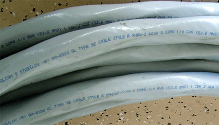
Photos 1 and 2. Feeders may come in various wiring methods, SE Cable or individual cables for just a couple of examples
Sizing the feeders
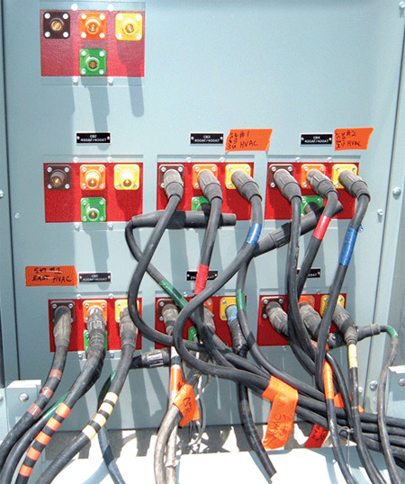
Photos 1 and 2. Feeders may come in various wiring methods, SE Cable or individual cables for just a couple of examples
Now that we have a grasp as to what a feeder is, let’s start to see what Article 215 requires for these conductors. In 215.2 theNECdiscusses the minimum rating and size. In another part of the code (Article 220), guidelines are given for calculating loads for various types of facilities. Section 215.2 states that the feeders must have an ampacity not less than the load calculated in the appropriate parts of Article 220. The feeders must be sized for 100 percent of non-continuous loads plus 125 percent of the continuous loads, and any applicable correction factors must be applied.
In 215.2(A)(2), requirements for grounded conductors are addressed, giving us the minimum size of the grounded conductor (which is generally a neutral). When you read this language, you will see the sizing reference is 250.122, which is the reference used for sizing the equipment grounding conductors downstream from an overcurrent device. Those of you who are familiar with most feeders know that we very seldom see neutral conductors sized this small. The minimum size required would be that ampacity required to carry enough current back to the overcurrent device to cause it to open in the event of a short-circuit fault condition. However, this is not what is typically found due to various other considerations within the code. First, on a single-phase system the neutral is calculated, and normally we find about a two wire gauge size reduction. In three-phase construction, the feeder neutrals are generally sized equal to the ungrounded conductors.
Feeders for individual dwelling units or mobile homes are not required to be any larger than the size of the service conductors. Now we have to take a closer look at this, since usually someone asks the question as to why the conductors are generally larger on all the services they see during inspection. We then begin the discussion of what is called the service point, and who has ownership, and what code applies to what portion of a system. The main issue is that a serving utility may provide a service with a conductor that is a lot smaller than that called for by the NEC, since their rules are not based on the NEC. To discuss this we have to establish the service point, which is the point at which the serving utility provides service. For most installations this is at the meter base if you have an underground lateral feeder. In this instance, the wire from the transformer to your meter base is owned by the power company and sized by the power company. Now most utilities that I am familiar with apply the National Electrical Safety Code (NESC), which has different requirements than the NEC. Also, the utilities will size the service conductors that they own by the anticipated demand, so if your house requires a 200-amp service according to the NEC, the utility will provide wire sized for about 100 to 120 amps. This is acceptable since they own and are responsible up to the service point, so they take the responsibility for those conductors. Now from the service point on, we are charged with enforcing the NEC and therefore size the feeders and service conductors accordingly. Please keep in mind this article is dealing with feeders and they will be downstream of any service conductors.
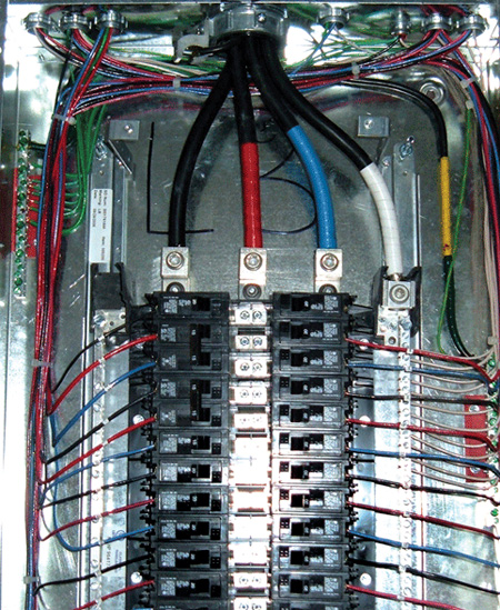
Photo 3.
As in previous articles in this series, we will be skipping the provisions of Article 215 that deal with anything over 600 volts, since a combination inspector would be unlikely to inspect such an installation.
Protecting the feeders
So once we’ve sized our feeders, how do we provide adequate protection for them? In 215.3, we find language that states the feeders will be protected as per Part 1 of Article 240. We haven’t covered 240 yet, but this would be a good time to take a look ahead and read over those requirements. Common sense says we should protect these conductors for the ampacity we calculate they will be subject to; however, we add one additional item. If we are feeding any continuous loads (those that will run for 3 hours or more at a time), we need to add an extra 25% of the continuous load values. Once we find the non-continuous load plus 125% of the continuous load, we have a value that we will use to size our feeder. Go to the proper ampacity table, match the load to a conductor which can handle that ampacity for the conditions to which it will be exposed, and then match it to the properly sized overcurrent device.
We have provisions in 215.4 for sharing neutrals with multiple sets of feeders. However, in most of the situations encountered by combination inspectors, it is unlikely that shared feeder neutrals will be found. Since it is very uncommon, I will not cover this in depth, just be aware that there are rules for that situation.
Diagramming the details
“Diagrams of Feeders” is the title of 215.5, and the wording is interesting. It states, “If required by the authority having jurisdiction, a diagram showing feeder details shall be provided…” Perhaps there are times where these types of plans would not be required by an AHJ. Residential may be the best one I can think of, due to allowances made for dwelling units and the diversity in the load calculations. However, in the years I have done inspections we always required proper plans and information as required by 215.5. This allows the plans checker to insure that the system is designed per code before it gets installed and then gets checked in the field. When the inspector gets on-site and reviews the approved plans which have gone through a proper plans check procedure, it is much easier for him to simply verify according to the plans than to have to sit down and open the code book to several sections for an inspection. It is a team effort to properly enforce the code, and this is a good example of that.
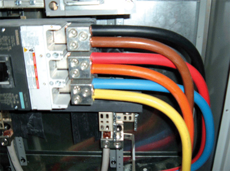
Photos 3 and 4. Various ways of conductor identification for feeders, some code-compliant and some not so.
If what we are going to serve with our feeders requires an equipment grounding conductor, then we must also make sure our circuit includes an adequately sized equipment grounding conductor according to the requirements in two different portions of Article 250. The first is 250.134, and if we have a separate building being fed then we must comply with 250.32(B). If you haven’t reviewed the code for a couple of cycles, please review the section regarding feeders to a separate building. The code has had a few changes to these requirements. What used to be an exception (but was the most common way of feeding separate buildings in reference to grounds) is now the actual code requirement general rule. In my opinion, the code panel did a good job of addressing this portion of the code and updating it to current field methods. The evolution has led to the fact that an equipment grounding conductor is the normal requirement rather than the exception. Remember that the grounding path is our safety line that provides a return path for current to pass through in the event of a fault. If properly installed and maintained, this path will allow the overcurrent device to open and shut down the circuit.
GFCI protection for personnel
“Ground-Fault Circuit-Interrupter Protection for Personnel” is covered in 215.9 and states that if you have branch circuits downstream of your feeders that require GFCI protection you have the option of providing GFCI protection of the feeders instead of protecting each separate device branch circuit. An example of this would be if the panel you were feeding required GFCI protection on each branch circuit and you were going to use GFCI receptacles for this protection, you might have to install 20 GFCI receptacles. The cost of this may be more than a GFCI breaker for the feeder, depending on the amperage of the feeder breaker.
GF protection of equipment
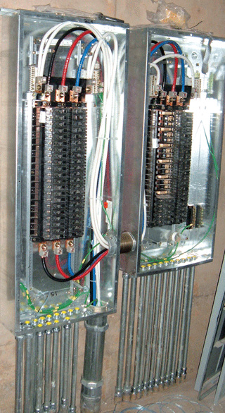
Photo 5. Here we have a feed thru panel on the left so the conductors from the bottom of the left panel are still feeders as they continue to the panel on the right.
The next portion of 215 we need to cover is 215.10, which deals with “Ground-Fault Protection of Equipment.” Although it has a somewhat similar name to what we know as GFCI, it is completely different. This protection is for a feeder disconnect rated 1000 amps or greater on solidly grounded wye electrical systems of more than 150 volts to ground, but not exceeding 600 volts phase to phase. What this boils down to is that we need ground-fault protection of equipment on feeders that are 277/480 three-phase systems, where the disconnect is rated 1000 amps or greater. This protection (unlike GFCI) is not intended for protection of people directly. It is designed for a shutdown of the protected circuit when a fault is detected to ground. The amount of the fault depends on the size of the disconnect and usually needs to be adjusted in the field for the exact installation. The levels at times may be around 200 amps or so, which is very different from GFCI protection. When dealing with ground-fault protection, make sure it is tested and adjusted properly as these devices come set at minimum levels and may cause nuisance tripping and a huge inconvenience to end users. Please make sure you take the time to review the definitions of GFCI and GFPE in Article 100.
Identification for feeders
The last item to cover in Article 215 is “Identification for Feeders.” This is covered in three paragraphs; however, the first two do the honorable thing and that is refer you to the proper code article for the identification of both grounded (neutral generally) which we find in Article 200.6. For the grounding conductors used in feeders, we are referred to Article 250.119. And, lastly, the identification of the ungrounded conductors is nearly identical to that of Article 210.5. So for a little review, if we have more than one nominal voltage system on a premise, then we have to identify each in a unique color code and properly post the identification code legend at each feeder panelboard of similar feeder distribution equipment. These identification requirements add to the consistency of the code for these types of conductors.
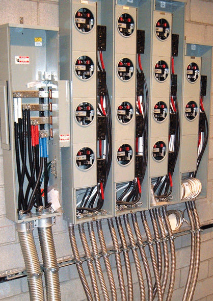
Photo 6. MC feeders feeding into and out of metering distribution equipment in a multi-dwelling high rise project.
As combination inspectors, Article 215 is one of those articles that we don’t refer to as often as many of the others such as 210 or 220. However, like I’ve told many of the individuals who are studying for various electrical exams, you need to have a fair understanding of what is there and be able to recall that we have a specific article for feeders. And when the situation comes up, something will trigger that memory and you will know where to go to find your answer. The average user of the code (and I include myself here) will never remember every article or exact point within the code to find whatever comes up, so don’t feel intimidated by those who can quote verbatim a lot of the code. When someone wants to dispute a particular code requirement, just simply say you want to look that up and review it. By having a fair idea where it is, you will show that you are a knowledgeable code user, and it gives you the opportunity to read the code and be sure what it says.
In the next issue, we will start into Article 220, which is full of the calculations needed to properly apply the code.



Find Us on Socials