An inspector’s first look at the service shown in photo 1 seems to show a relatively simple 120/240-volt single-phase service. It seems to include a service entrance riser, a service entrance wireway, and four 200-ampere fused disconnects, fused at 150 amperes. Disconnects are marked “Suitable for Use as Service Equipment.” Each disconnect has a tap to the grounding electrode conductor and includes a green bonding screw for the main bonding jumper. Each disconnect supplies a separate panelboard. These panelboards are located on each of four concrete light poles to provide branch circuits to the junior high school football field light fixtures at the top of the poles. All fixtures are 240 volt. The grounded circuit conductor is installed to each service disconnect even though there is no 120-volt load. This will provide a path for fault current. This seems to be a simple installation to inspect.
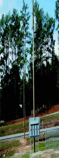
However, after reviewing the above installation, the inspector notices that the utility metering is located on another pole behind and to the left of what he had assumed was the service. The simple installation now becomes quite a challenge.
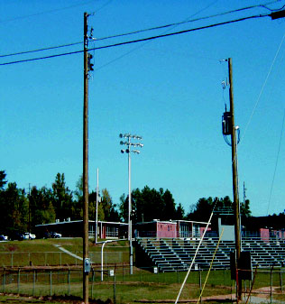
A closer look finds the service point, “the point of connection between the facilities of the serving utility and the premises wiring,”1 on the utility meter pole (see back left pole in the photo 1, left pole in photo 2).
The service drop, “the overhead service conductors from the last pole or other aerial support to and including the splices, if any, connecting to the service-entrance conductors at the building or other structure,”2 from the service point to the customer pole is premise wiring and within the scope of the NEC. The service is 7200 volts, one phase of a grounded 12,470-volt utility system. Moving the service point to the primary side of the transformer will require the installer and inspector to consider many additional Code sections in order to approve the installation. In addition to installation requirements, the inspector will also be responsible for approval of equipment that will not be listed.
This review of the installation begins in Article 230, Part H, Services Exceeding 600 Volts, Nominal. Section 230-200 indicates that all applicable sections of Article 230 shall apply unless modified by Part H. Complying with the requirements preceding Part H will present several challenges. Article 230 reveals where these challenges are found.
The requirements found in Article 230, Part A seem to be met.
Part B covers overhead service-drop conductors and is not modified by Part H. Section 230-22 requires service-drop conductors to be insulated except for the grounded conductor of a multiconductor cable. If the conductors from the utility meter pole to the transformer pole were on the line side of the service point, the NESC would permit them to be bare if properly separated. That permission does not exist in the NEC.
Part C, which covers underground service-lateral conductors, is not applicable to this installation.
Part D covers service-entrance conductors, which are defined in Article 100 for overhead systems as, “the service conductors between the terminals of the service equipment and a point usually outside the building, clear of building walls, where joined by tap or splice to the service drop.”3 Section 230-202 amends Part D, by referring to Section 300-37 for wiring methods. That section permits the bare conductors used on this installation. Minimum conductor size is established in 230-202, and the No. 6 minimum requirement has been met. Although Part D requires the service-entrance conductors to have an ampacity to carry continuous and noncontinuous load, 230-202 only requires a minimum No. 6 conductor. At this project, the No. 6 will certainly carry the load. Clearances are provided in Parts B and D for installations 600 volts or less. In Part H under Section 230-200 there is a fine print note (FPN) which is described in Section 90-5(c) as, “explanatory material, such as references to other standards, references to related sections of this Code, or information related to a Code rule, is included in this Code in the form of fine print notes (FPN). Fine print notes are informational only and are not enforceable as requirements of this Code.”4 This FPN under Section 230-200 states that “for clearances over 600 volts…see the National Electrical Safety Code.”5 The question is whether the jurisdiction will enforce the FPN or do something else.
Part E covers service equipment, defined in Article 100 as, “the necessary equipment, usually consisting of a circuit breaker(s) or switch(es) and fuse(s) and their accessories, connected to the load end of service conductors to a building or other structure, or an otherwise designated area, and intended to constitute the main control and cutoff of the supply.”6 Part E is modified by Section 230-210, which refers to Article 490, Part A. These requirements will not make the inspection job more difficult.
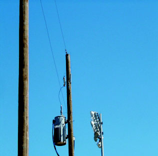
Photo 3
Part F covers service equipment-disconnecting means, which is modified by Section 230-205. This section requires the service disconnecting means to be installed at a readily accessible location, either outside or inside, nearest the point of entrance of the service conductors. The outside part of this rule is great for the stadium lighting job; however, the readily accessible part will require some consideration by the inspector. Readily accessible is defined in Article 100 as, “capable of being reached quickly for operation, renewal, or inspections, without requiring those to whom ready access is requisite to climb over or remove obstacles or to resort to portable ladders, etc.”7 If this service disconnect were located at a large industrial facility that employed qualified electricians, equipped with proper tools and equipment, one could at least argue that the switch was readily accessible to those that needed to reach it. An inspector would have to think about whether the parents, coaches, and school maintenance personnel that might need to operate the disconnect would find it readily accessible.
Section 230-205(b) also requires that the service disconnect have a fault-closing rating that is not less than the maximum short-circuit current available at its supply terminals. The equipment (photo 3), to my knowledge, is not listed and will not have third party verification that this requirement is met. (The information may be provided by the manufacturer?)
Part G covers service equipment-overcurrent protection, which is modified by Section 230-208 and is required to protect the ungrounded conductors it supplies. Tables 310-67 through 310-86 provide ampacities for insulated conductors rated 2001 volts and above. Section 310-15(b)(3) provides information for ampacities of bare conductors. It will not help where all conductors of a system are bare. Section 230-208(a) requires compliance with Part B of Article 490 for equipment used to protect service-entrance conductors. The requirements found in Part B cover interrupting ratings, voltage ratings, nameplate requirements, and design, arrangement, and installation of fuses and fuseholders to minimize hazard to persons and property when fuses clear faults. The requirements seem clear, but this equipment is normally purchased and used on utility systems and is not listed. The jurisdictions with listing requirements for equipment will have to determine how they want to address that issue.
Article 110, Part C addresses general requirements for installations over 600 volts, but does not seem to address installations on poles. Section 110-34(e) provides elevations of unguarded live parts. Workspace when equipment is at the top of a pole does not seem to be addressed; the AHJ would have to determine if adequate space is provided to operate the switch with a hook stick from the ground.
The installation shown involves one branch circuit to a 100 kVA transformer. Articles 210, 215, or 225 do not seem to provide specific requirements for this circuit. The 40- ampere fuse at the service cutout seems to comply with Section 240-100 and protects the conductor from the cutout to the transformer.
The 7200-volt primary, 100 kVA, 120/240 volt secondary, oil-filled transformer is not listed. UL Green Book has a category (XPLH) Transformers, Distribution, Liquid-Filled Type, Over 600 V; this guide card information indicates that these are pad-mount and sub-station type. The transformer used at the stadium is one that is normally installed by utilities and would not normally be listed. Again, the AHJ will have to address that issue locally. Table 450-3(a) will address the transformer overcurrent protection. Primary fuse protection will be 300 percent of the primary current rating of the transformer. Current rating of the transformer will be 13.9 amperes. The 40-ampere fuse is within the limits shown in the table. Table 450-3(a) also requires secondary transformer protection rated at 125 percent of the secondary rated current. The secondary overcurrent device shall be permitted to consist of not more than six circuit breakers or six sets of fuses grouped in one location. Where multiple overcurrent devices are utilized , the total of all the device ratings shall not exceed the allowed value of a single overcurrent device. Secondary current for the transformer used is 416.7 amperes. Maximum value of the overcurrent protection is 520 amperes, rounded to the next standard size of 600 amperes. So the four 150-ampere fused switches provide the secondary transformer protection. The wireway and four fused switches do not comply with Section 240-21. Since this is not a service, the taps in the wireway are connected to a transformer tap.
In conclusion, the moving of a service point can cause a real adjustment in the time taken to do a simple stadium lighting job.
1 NFPA 70, National Electrical Code, 1999 Edition, (Quincy, MA, National Fire Protection Association, Inc., 1998. p. 70-24.
2 ibid
3 ibid
4 NFPA 70, p. 70-18.
5 NFPA 70, p. 70-69.
6 NFPA 70, p. 70-24.
7 NFPA 70, p. 70-19.