
Like most of you, I have been an electrician for many years and came from a time in which energized work was an acceptable practice. Since that time, standards such as OSHA and NFPA 70E have evolved to help minimize hazards in the workplace.
NFPA 70E®, Standard for Electrical Safety in the Workplace, is a best practice to provide a practical safe working area for employees and to help reduce electrical hazards and workplace injuries. Electrical hazards can include electric shock, arc flash, and arc blast.
Electrical Hazards
When discussing electrical hazards, electrical shock is the one that we are most familiar with. In fact, most of the electrical fatalities in this country are related to electrical shock as opposed to arc flash. However, arc flashes are serious hazards as well. The pressure waves coming from an arc flash event can make it even more difficult to protect people (as opposed to the thermal events). Other hazards can include incidents such as falling off a ladder from an electric shock or being sent backwards from an arc pressure wave into a wall or another piece of equipment.
Electrically Safe Work Practices
When it comes right down to it, we are our own last line of defense.
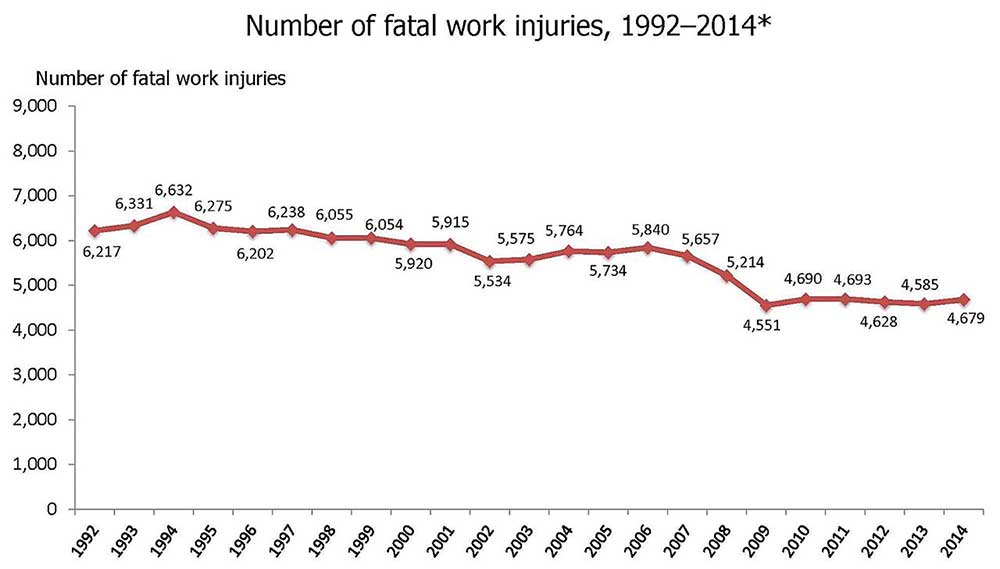
Figure 1 shows the number of fatal work injuries, although it does fluctuate from time to time. The overall number of fatal injuries has declined over time, which I believe is the direct result of safer work practices.
It’s important to look at where we lie in the spectrum of the workplace? In other words, what do you do for work? As an electrical inspector and electrician, I can relate to both sides of the fence.
An electrical inspector, for example, has more indirect exposure to electrical hazards than a more hands on approach. It’s being aware of the surrounding and what state the equipment is in. For example, I have been an electrical inspector for a number of years, and we really don’t interface with a lot of energized equipment unless we happened to be doing some type of an investigation the involves energized equipment. But overall, we were just inspecting for Code compliance and not really hands-on.
When I worked for the State of New Hampshire, very rarely did I have to be involved in a lock or tag out situation where equipment had been de-energized and needed to be controlled from being re-energized. Yet on the sites I work now, there are times I have to place a lock on the equipment’s isolating device because the equipment is connected to a voltage source and I’m going to come in contact with, or be in close proximity to, exposed parts. That’s a different level of inspection than what I did in the past.
The installer is going to be more hands on. With new installations, a lot of that is going to be de-energized and doesn’t present hazardous energy until the end when it connected to a source of voltage and could become energized. If you are in a maintenance role as an electrician, you are more involved with direct exposure to the hazards.
The designing engineer is more similar to the electrical inspector as it is generally not hands-on, touching. The same could be said for the safety manager. The safety manager is usually responsible for the safety of other people as well as their own safety.
We all have different roles in electrically safe workplace practices.
Identifying the Hazards
Exposure to shock is the most predominate cause of electrical fatalities in this country. If you look at the language in the Annex K of the 2021 version of NFPA 70E, it states that electrical shock is responsible for about 98 percent of fatal occupational injuries. Electrical shock requires exposure to a difference of potential. The National Electrical Code (NEC) does a great job reducing that hazard under normal conditions. NFPA 70E takes over when things are not in a normal condition. The interesting thing about shock hazards, compared to arc flash hazards, is that they only really exist when we’re exposed to energized conductive parts.
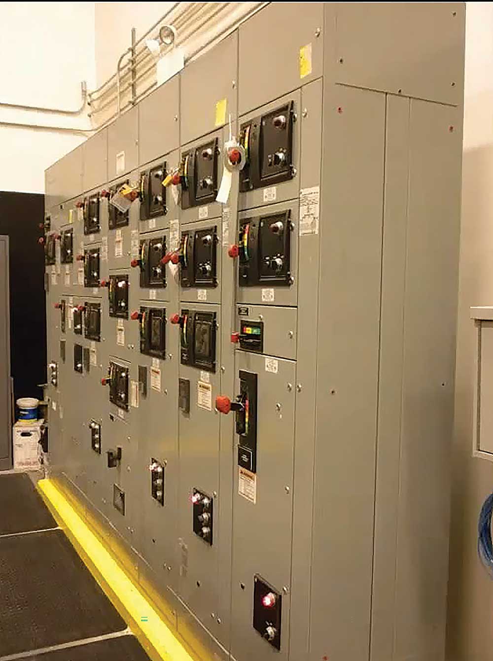
Photo 1 is an example of a 480-volt motor control center that shows what normal operating condition is. It doesn’t pose a shock as we don’t have any exposed parts. Everything is enclosed, all of the openings have been closed and there is no open knock-outs or any place for people to come in contact with hazardous energy. Normal operating conditions generally do not pose a hazard to us, at least from a shock standpoint.
When NFPA 70E considers arc flash, it looks at from a curable burn standpoint and what is greater than an acceptable arc-flash hazard. In arc flash terms, 1.2 calories per centimeter squared is the onset of a second-degree burn on bare skin. We don’t really use the term curable burn in the document, but it’s about being able to return to work in the same capacity that you were originally and needing only minor burn treatments.
Remember that 70E is not a suit of armor. However, it has helped to improve safety. For example, personal protective equipment (PPE) performs better than we could have expected, and the results are certainly indicated in the downtrend of injury.
Photo 2 is two older examples of abnormal operating conditions. You can see that the equipment is open and not in its normal operating state. In the photo on the right-hand side, the gentleman is doing an absence of voltage test. It’s hard to see the meter in the example, but shows zero voltage. However, until you go through all of the steps of establishing an electrically safe working condition, we have to consider it as an energized source. The photo on the left is interesting as it goes back to the early days of NFPA 70. At that time, the goal was for the worker to be provided with personal protective equipment (PPE), trained to understand how to use it and to wear it. It is unlikely today the task being demonstrated there could be justified on energized equipment.

Reacting to Electric Shock
Electric shock was the original purpose of NFPA 70E. It was basically information from the NEC relating to worker safety, such as closing equipment, proper working distance, properly sizing overcurrent protection and equipment grounding conductors, and so forth. To reduce electric shock hazards, we have to understand how we get exposed to it and how people react to it.
Figure 2 shows some different ways that shock travels through the human body (touch potential). The voltage between any two points on a person’s body (such as hand to hand, hand to foot, etc.) is called touch potential. Step potential is the voltage difference between a person’s feet, i.e., the difference in voltage between two points of a walking surface. The current that passes through the heart and lung area is the most serious type as it deals with the muscles related to heart activity and lung function. Whether it is hand to foot or hand to hand, I’m sure that most people involved in the electrical industry have experienced at least one of these pathways in their electrical careers.
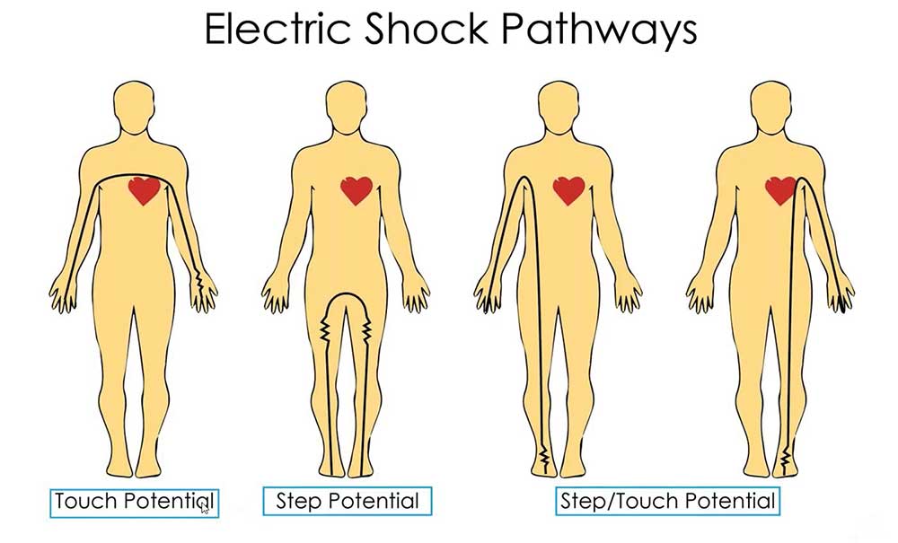
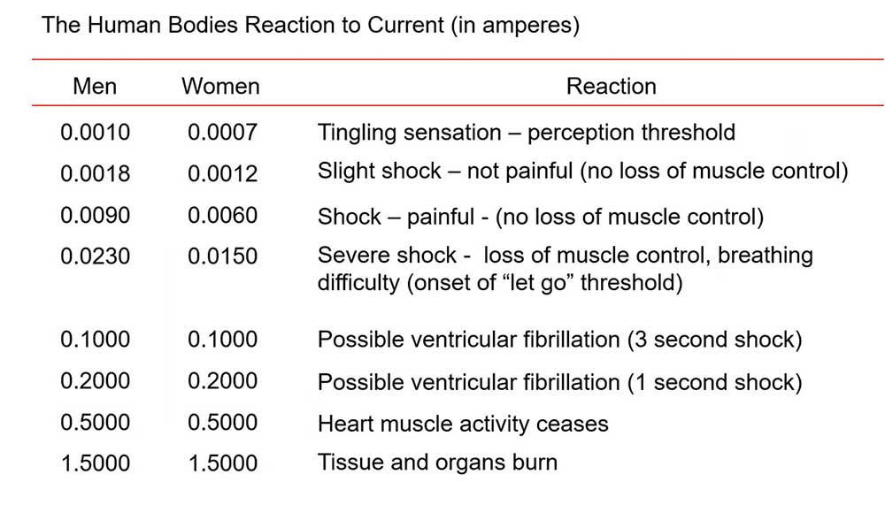
Figure 3 is an older illustration that shows the effect of different levels of electrical current (in milliamps) on men and women. You can feel the shock with less than one milliamp in both men and women. It gets a little more painful at 6 or 9 milliamps. At half an amp (0.5000), the heart muscle can cease activity. You can also see that ventricular fibrillation can occur at 100 or 200 milliamps depending on the length of time.
Shock Protection Boundaries
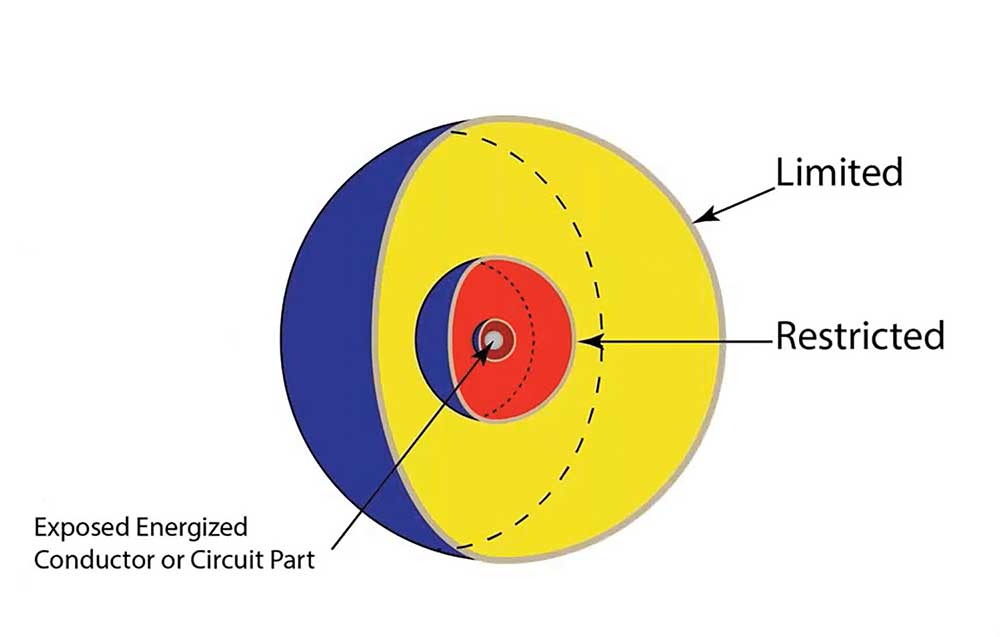
One of the ways that NFPA 70E deals with shock awareness or shock protection is by identifying the shock awareness boundaries known as the limited and restricted approach boundaries (see Figure 4). The limited approach boundary (LAB) is the onset of the qualified person space and the line of demarcation for the unqualified person. You’ve got to be a qualified person to cross the LAB. Unqualified persons cannot cross the LAB unless they are continuously escorted by a qualified person. When the Restricted Approach Boundary (RAB) is crossed, shock protection techniques must be employed and you must be a qualified person. Unqualified persons are not permitted to cross the RAB.
Arc Flash
So, there are a variety of questions people have about arc flash. What is it? How do we deal with or manage it, and how can we reduce the exposure to it? These are just some things that we have to think about when we deal with arc flash. So, we can always create an arc. The question is, can you create an arc flash? I can create an arc with a nine-volt battery if I want, but I’m certainly not going to have enough energy to create an arc flash. There would have be enough energy in the arc to ionize the air between two components, such as between busses or between phases, and cause a conductive pathway to create an arc flash. So, in a given situation, the question will be, do I have enough energy to create an arc flash? It’s probably difficult, but not impossible, with 208-volt and 240-volt systems but it is certainly possible in a 480-volt system where I have plenty of energy to create an arc flash.
Again, the question is, will it rise to that level? When it does rise to that level, I can have an arc plasma fireball. Temperatures can go up to or exceed 35,000 degrees, which is approximately four times the temperature of the sun’s surface. There is a rapid heating of air and expansion when copper vaporizes, creating loud blasts and pressure waves. Figure 5 is one of the early Bussmann illustrations, and you can see some of the things that occur during an electrical arc event.
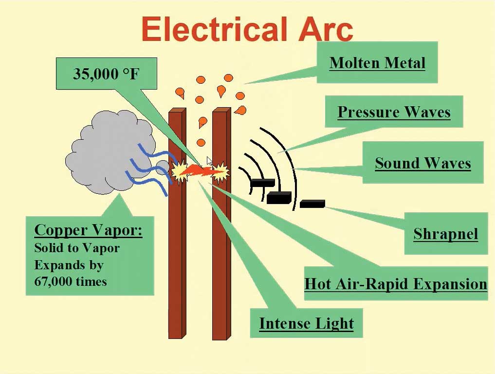
The issue is that once there is enough energy to ionize the air between two energized components, such as these two busbars (two points) in Figure 5, for example, then there is the potential to create the arc flash. When it occurs the molten metal, the pressure waves, and the sound waves are likely.
When it happened to me, I was working in a 400-amp, 480-volt, panel and a metal plank plate fell inside the panel and got between the equipment enclosure and a phase (stud on a busbar). It sounded like somebody shot a 12-gage shotgun off in the building. Fortunately, I didn’t get a thermal burn because of the configuration, but my I was blinded for about an hour and a half, and I believe that it was from the intense light that occurred.
Responsibilities and Priority
From an NFPA 70E and an OSHA standpoint, it’s the employer’s responsibility to provide safe work practices. They’re going to have to train the employee. The employee must carry out said safe work practices designed by the employer. This is generally through the electrical safety program. Eliminating the hazard is the first priority when considering electrical safety-related work practices.
Controlling or eliminating the source even for a period of time is important. In my opinion, the only true way to eliminate the hazard is for the equipment to be disconnected from the voltage source all together, as in new construction, where it hasn’t been energized yet or connected to anything that could potentially energize it. We can certainly eliminate the hazard for a period of time by controlling it through lockout or tagout.
One of the focuses, especially lately, from an OSHA standpoint, is that the employer is responsible for implementing and documenting an overall electrical safety program (ESP). Rather than just handing out copies of NFPA 70E (which is a great start), employers should create an ESP that focuses on what activities are actually taking place in the facility or the site where they work. These programs can vary greatly depending on the type of work performed and whether it is an industrial facility or an electrical contractor. Electrical contractors face an additional challenge as they work in different facilities where they not only have to employ their own electrically safe work practices, but they may have to meet the safe work practice standards of the facility they are working in.
Electrical safety programs are discussed in Section 110.5 of NFPA 70E in the 2021 edition. Elements of an effective program are broken out in this section and include:
- Inspection (B)
- Conditions of maintenance (C)
- Awareness and self-discipline (D)
- ESP principles (E)
- Controls (F)
- Procedures (G)
- Risk assessment procedure (H)
- Human error (H)(2)
- Hierarchy of risk control methods (H)(3)
- Job safety planning and briefing (I)
- Incident investigations (J)
- Condition policy (K)
- Lockout/tagout program (L)
- Auditing (M)
One of the elements of the ESP is inspection. Newly installed or modified electrical equipment must be inspected for compliance with applicable codes. In order for electrical equipment to be in a normal operating condition, it must be properly installed, and an electrical inspection is a critical part of that determination. An electrical contractor would not likely have this element as part of their electrical safety program, but would have to consider it in a facility they are going to work in. Unfortunately, not all industrial facilities have the same level of inspection.
Another important aspect of this type of program is the conditions of maintenance? How has the equipment been maintained? Is there adequate documentation about maintenance procedures? From an arc flash standpoint, it has a lot to do with clearing times and what we can estimate for burn energy. Most electrical safety program requirements don’t mandate maintenance of overcurrent devices (e.g. circuit breakers) but rather that consideration must be given to the condition of maintenance and how that will affect the operation of the equipment from an arc flash standpoint.
Training
Qualified persons are required for performing testing, troubleshooting, and voltage measuring, when dealing with energized electrical conductors or circuit parts operating at 50 volts or more. A qualified person is trained and knowledgeable of equipment or a specific work method. They must be familiar with the hazards, the applicable policies and procedures, related PEE, shielding materials, tools, and test equipment. As we talked about earlier, if we’re going to cross the LAB, the qualified person will need the necessary additional training. For example, individual must be able to distinguish exposed energized parts from ones that aren’t, determine the nominal voltage of exposed energized conductors and circuit parts, and establish the shock approach distances for corresponding voltage. Is the nominal voltage 480 or 208?
NFPA 70E 110.6(I) notes that qualified individuals working with the limited approach boundary must also be trained in performing job safety planning, identifying electrical hazards, assessing the associated risk, and be able to select the appropriate risk control methods from the hierarchy of controls identified in 110.5(H)(3) [in the 2021 version].
Retraining
For a couple of cycles now, NFPA 70E has stated that retraining is generally a three-year requirement which coincides with issuing of the newest edition of NFPA 70E. I personally feel that retraining must include looking back over the last three years and seeing what lessons we’ve learned. For example, how are the employees reacting to electrical safety work and safe work practices? Are there things that we need to focus on? This is in addition to knowing what the new requirements are in the latest edition of NFPA 70E.
NFPA 70E 110.6(A)(3) also notes that retraining must be done more often under certain circumstances, such as if someone isn’t complying with the safe work practices, if the company gets new technology, the employee’s job duties change, or if the task is performed less than once a year. For example, if the task is performed less than once a year the retraining session can be a basic review of the task.
Testing Instruments, Equipment, and Accessories
Let’s talk about test instruments. When discussing testing equipment, we have to consider the steady-state voltage and transient overvoltages. That was some of the problems with legacy equipment as most of it was identified for the steady-state voltage but surge or transient overvoltage was not considered. Meters today are required to be rated in categories based on impulses or overvoltages at different points on the system (Category I, II, III, and IV). Category I is the weakest category, with Category IV being the strongest. Voltage ratings are for normal voltages and are typically 600 or 1000 volts.
One example of a standard dealing with safety equipment is UL 61010-1, Electrical Equipment for Measurement, Control, and Laboratory Use, Part 1: General Requirements.
Photo 3 has a couple of examples of test instruments. The one on the left-hand side is Category IV at 600 volts and Category III at 1,000 volts, which is a very common rating. The right-hand side photo is a proximity tester or non-contact tester (depending on how you want to call it). Noncontact type test instruments can be used as a cursory test before performing an absence of voltage test, but certainly couldn’t be used under the establishing an electrically safe work condition guidelines as a final test. One of the limitations of these test instruments is the lower voltage threshold depends on the strength of the battery. For example, if the low voltage threshold sensing is 50 volts, it could increase to 70 volts or higher as the battery weakens.
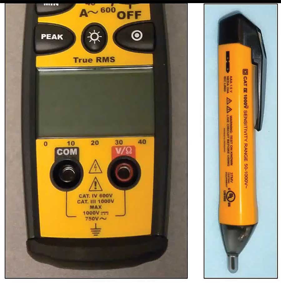
On the backside of most test instruments, you should look for the mark from a nationally recognized testing laboratory. For example, on the side of the meter in photo 3 is a UL mark down at the bottom. Finding such a mark indicates that the device has been tested to meet the product standard, and that is very important when trying to determine safety.
Meter probes also have category ratings as well as an insulated tool rating.
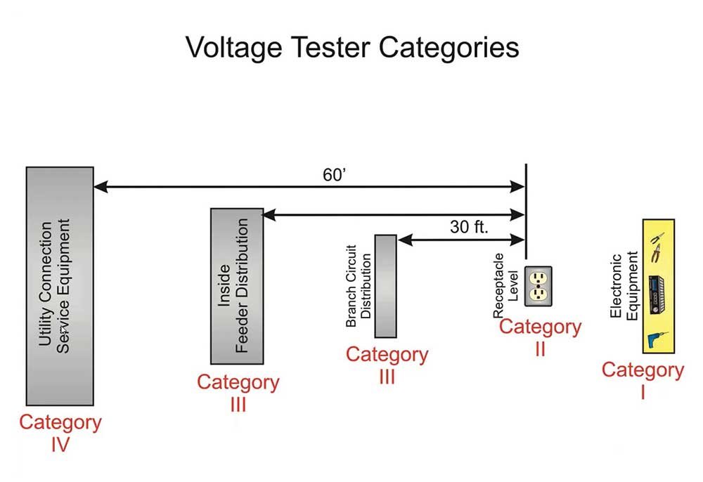
Figure 6 is a summary of the different categories. Category IV is utility equipment, I call that the first level of distribution equipment, where the power supply is coming into the building. That would be the first level of equipment in the building or just outside the building — utility connections and service, service equipment, and connections on an industrial site that could be feeders. At that first level (Category IV) is where you have a potential for higher voltages or surges from upstream lightning strikes or cross over of higher voltage lines and switching spikes. The second level is Category III, which includes inside feeder distribution equipment, large polyphase motors, control panels, etc. Category III also includes branch circuit distribution levels. I haven’t seen many Category II meters myself personally, but you notice that if you have a receptacle level test going on that to be considered a Category II location, it has to be 30 feet from a Category III location or 60 feet from a Category IV location. Category I is, of course, bench work or electronic equipment.
Article 130 — Work Involving Electrical Hazards
Finally, let’s take a quick walk through some work involving electrical hazards, as mentioned in Article 130 of NFPA 70E. Article 130 covers when an electrically safe working condition must be established and also the requirements for electrical safety-related work practices when an electrically safe work condition cannot be established. I also like to say “it applies when establishing an electrically safe working condition.” Remember that until all of the steps of establishing an electrically safe working condition have been performed, the equipment is considered to be energized. So it’s no different than working on equipment while it is energized. The way that I would like to explain it is that if I was doing an absence of voltage test and I determined that I had to work on that equipment to do some type of troubleshooting when it was in an energized condition, I should not have to add additional personal protective equipment (PPE). In other words, if I turn the equipment off and I’m going through the steps to determine the absence of voltage, if I had to re-energize the equipment to do some troubleshooting then I shouldn’t have to change my PPE at all. The PPE that I have on to establish the electrically safe working condition should not be any different than if I was going to do energized work on that equipment.
When considering electrically safe work practices, the goal is to establish an electrically safe working condition where there are exposed conductors and circuit parts operating at greater than 50 volts. So, an electrically safe work condition is required to be established if the employee is within the limited approach boundary. That’s an easy one; covers are off, and we’ve got energized components. Without exposed energized conductors or circuit parts, I don’t have a shock hazard and therefore I don’t have a limited approach boundary.
On the other hand, if I’m dealing with equipment where conductors or circuit parts are not exposed, and there’s an increased likelihood of exposure to an arc flash, establishing an electrically safe working condition is required. So, if I’m interacting with a piece of equipment and there’s a potential for injury from an arc flash, the intent is not just to put somebody in PPE and have them interface with the equipment. The idea is to put the equipment in an electrically safe work condition unless there is justified energized work. The first choice today is to establish the electrically safe working condition rather than putting on PPE and doing unjustified energized work.
OSHA Regulations
OSHA looks at construction differently from the general industry from a lockout or tagout perspective. Even in an existing application, if I am adding on a new section onto a piece of switchgear, that’s considered a construction activity and requires the employer to render the equipment inoperative. For example, from a general industry perspective, OSHA 1910.133(b)(2), Locking and Tagging, requires the employee to place a lock or tag on circuits energizing exposed parts that have been de-energized. On the other hand, from a construction perspective, OSHA 1926.417, Lockout and tagging of circuits, (b), Equipment and circuits, states that equipment or circuits that are de-energized are to be rendered inoperative and that tags are to be attached at all points where such equipment or circuits can be energized. NFPA 70E does not distinguish general industry applications from construction applications. It treats everything as a general industry application.
Establishing an Electrically Safe Working Condition
To establish an electrically safe work condition, NFPA 70E 120.5 has eight steps for establishing and verifying an electrically safe work condition. We don’t have space to cover all of these steps in detail, but here is a quick overview of the eight steps identified in the document. These include:
(1) Identify all possible sources and check drawings
(2) Open disconnects
(3) Visually verify the opening of contacts where possible
(4) Release stored electrical energy
(5) Release or block stored mechanical energy
(6) Apply lockout/tagout devices
(7) Test voltage and verify operation of the tester, and
(8) Apply safety grounds where necessary (normally in larger systems).
All of these steps must be performed in order to determine that an electrically safe working condition has been established. So, basically, the OSHA regulations parallel what we talked about. You need to de-energize before the work begins unless the employer can verify an increased hazard or an operational limitation (less than 50 volts). NFPA 70E mirrors that language and says that energized work can be permitted where the electrical circuit parts and conductors operate at less than 50 volts (with conditions); the employer can demonstrate that de-energizing creates a greater hazard; that de-energizing is infeasible and for equipment that is in a “normal operating condition.”
What determines a normal operating condition? Well, here are a few variables to consider a normal operating condition. The equipment must be properly installed, maintained and used in accordance with instructions included in the listing and labeling and in accordance with the manufacturer’s instructions. In addition, the equipment doors must be closed and secured, all covers must be in place and secured, and there is no evidence of impending failure.
Energized Electrical Work Permit
An energized electrical work permit (EEWP) is required when work is performed within the restricted approach boundary or if the employee interacts with equipment where conductors or circuit parts are not exposed, but there is an increased likelihood of injury from exposure to an arc flash hazard. Let’s say that we’ve got the covers off, there are exposed live parts, and the worker is going to be crossing the restricted approach boundary. An EEWP would be required. Conversely, if there are no exposed parts but the worker is interfacing with the equipment and there is an increased likelihood of injury from and arc flash, an EEWP would also be required.
Elements of a work permit can vary depending on the facility. Whether it’s a facility manager or safety management, it usually requires some level of sign-off to perform the task. You need to have justification for the energized work and include information that indicates familiarity with circuits and equipment. This includes a shock and arc flash hazard risk assessment, establishing protection boundaries, proper PPE, a job briefing and restrictions (barricade) for unqualified persons. Annex J of NFPA 70E has an example of an energized electrical work permit.
There are some exceptions, such as testing, troubleshooting, and voltage measurements, from having to complete an EEWP. Additional exceptions include thermography, ultrasound, or visual inspections if the restricted approach boundary is not crossed or if there is access to and egress from an area with energized equipment, no electrical work is being performed, and the restricted approach boundary is not crossed. General housekeeping and miscellaneous tasks are exempted as long as the restricted approach boundary is not crossed.
Summary
One of the most critical steps to remember when determining electric shock and arc flash hazards is to always test before you touch the equipment. You always want to conduct a test at the point where you’re going to work. You can do an absence of voltage test upstream of where the work will be performed, however, NFPA 70E will require you to do an additional test before you touch at the point where the work will be performed.