
Keeping employees safe at work has to be responsibility number one for a company. What is the rationale for being profitable if unsafe, or delivering product quickly to the customer if the workplace is unsafe and so everyone agrees that workplace safety is a priority but then we need to ask why are the incident rates of electrical injuries and in some case fatalities not reducing year over year, if keeping employees safe is a priority?
From 2011 to 2020 the rate on non-fatal injuries due to exposure to electricity remains relatively unchanged despite extensive campaigns around electrical safety and the use of PPE.
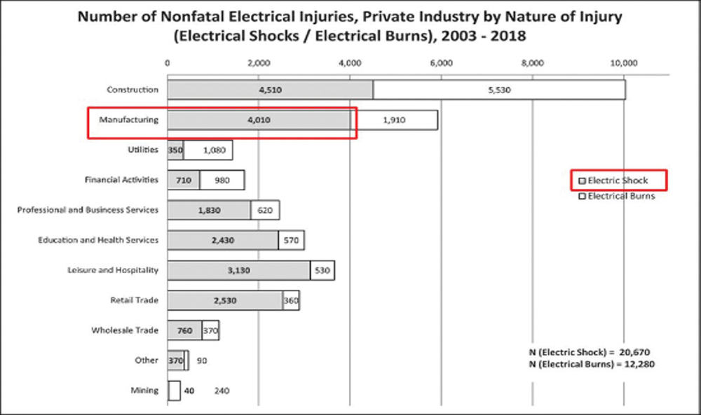
Figure 1 is for all establishments, not specifically manufacturing establishments, that tend to have the second-highest incident rates after construction.

From 2003 – 2018, there were 1,910 electrical burn injuries in manufacturing establishments; the typical cause is arc flash incidents. These receive a lot of press coverage due to the devastating nature of an arc flash and the destructive impact.
Yet, during the same period, there were 4,010 electric shock incidents in manufacturing facilities. While 50% of victims only missed 1-2 days of work, more than 25% missed three weeks or longer due to their injuries.
Perhaps the greater concern is that there was an increase from 2019 to 2020 in the number of incidents that were related to installation, maintenance, and repair of equipment and that while the expectation would be that these were inexperienced personnel, statistical data indicates that 33% of the workers impacted by an electrical hazard had more than one year of experience and 32% had more than five years of experience (see Table 1).
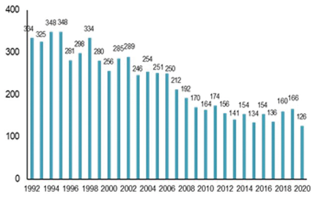
One positive trend is the reduction in fatalities due to exposure to electricity, from 166 in 2019 to 126 in 2020. However, some of this is attributable to the covid-19 pandemic and reduced hours being worked at manufacturing facilities that are not considered essential.
Therefore, the question is what can be done to ensure electrically safe work conditions and reduce the number of fatal and nonfatal injuries each year.


Electrically Safe Work Condition is a state in which an electrical conductor or circuit part has been disconnected from energized parts, locked/tagged out in accordance with established standards, tested to verify the absence of voltage, and, if necessary, temporarily grounded for personnel protection.
There are two references with respect to establishing an electrically safe work condition. The first is OSHA (Occupational Safety and Health Administration), and the second is National Standards.
It would be NFPA 70E, Standard for Electrical Safety in the Workplace, for the US. In Canada, it is CSA Z462, Workplace Electrical Safety, and similar publications for other countries.
In OSHA 1910, Occupational Safety and Health Standards, Section 1910.333, Selection and Use of Work Practices, states the following:
1910.333 a) Safety-related work practices shall be employed to prevent electric shock or other injuries resulting from either direct or indirect electrical contacts, when work is performed near or on equipment or circuits which are or may be energized.
1910.333(b)(2)(iv)(B) A qualified person shall use test equipment to test the circuit elements and electrical parts of equipment to which employees will be exposed and shall verify that the circuit elements and equipment parts are de-energized. The test shall also determine if any energized condition exists as a result of inadvertently induced voltage or unrelated voltage back-feed even though specific parts of the circuit have been de-energized and presumed to be safe.
Both NFPA 70E and CSA Z462 have undergone significant changes over the past eight years, as noted below.
In the 2015 edition, the only prescribed option to verify an electrically safe work condition was to use a multimeter and test the phase conductors or circuit paths directly. This requires opening the door to the electrical cabinet after donning the appropriate safety equipment and making direct contact. This approach involves risk from unintentional contact with possible current-carrying conductors or selecting a meter that is not adequately rated or set incorrectly.
An industry study indicated that 18.3% of facilities experienced personnel injuries when using handheld meters to conduct the test.
In 2018, NFPA 70E was updated and introduced the option to use an adequately rated permanently mounted electrical test device to verify the absence of voltage. This led to the proliferation of companies using voltage indicators and test ports to conduct this important test. The rationale was simple, you conduct the test with the door closed and therefore reduce the risk of unintentional contact with current carrying conductors, and the end result should be a substantial reduction in the fatal and nonfatal statistics.
No such reduction in incident rates occurred, and the question needs to be asked why one simple explanation may be that the products being used were not suited for the specific application.
Reading zero volts at the end of a test port simply indicates that there is no voltage at the test port does not guarantee absence of voltage on the current-carrying conductors. What if a lead is missing or loose? What if the fuse between the test port and the current-carrying conductor is blown? In each instance, you would read zero on the meter inserted into the test port, but the actual situation would remain dangerous due to voltage still being present. Perhaps qualified workers do not 100% trust the results from using a voltage test port and resort to opening the door to the electrical cabinet thereby putting themselves at risk.
In 2021, NFPA 70E went through further updates, and in 120.5 Rule 7, the term “verify it is de-energized” was changed to “test for the absence of voltage.”
The Exception was also changed, and the term electrical test device was removed and replaced with the absence of voltage tester with an informational note that an absence of voltage tester must meet the requirements of UL 1436. These changes eliminated the option to use voltage test ports.
According to UL 1436, an absence of voltage tester is defined as:-
A permanently mounted test device that is used to verify that a circuit is de-energized prior to opening an electrical enclosure that contains energized electrical conductors or circuit paths. An AVT is provided with a test circuit with active indications to verify the absence of phase-to-phase and phase-to-ground voltage.
On the surface an absence of voltage tester does not appear to be different from a voltage indicator but there are significant differences and all related to the design, architecture and operational clauses contained with UL 1436. An absence of voltage tester undertakes all the same tests as a qualified person would undertake using a multi-meter. That is all current carrying conductors and circuit parts are measured phase to phase and phase to ground to verify that there is an absence of voltage. The absence of voltage tester must also ensure via a supervisory circuit that it is functioning satisfactorily and that it conducts continuity checks to verify that all connections are secure and connected in the correct manner.
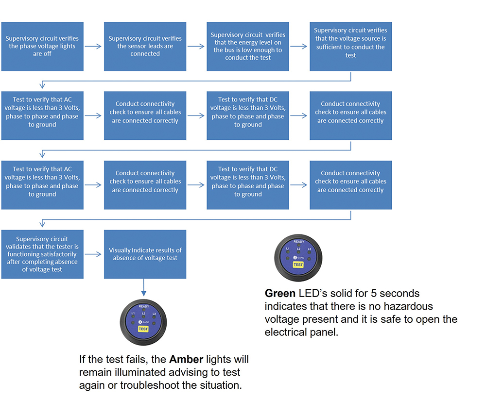
The test sequence of the absence of voltage tester is visually represented below and the entire sequence is performed in around 10 seconds and all with the door to the electrical cabinet closed and personnel removed from the risk of unintentional contact.
If the test is successful and there is less than 3 volts AC or DC present in the circuit, then the absence of voltage tester will provide three (3) green lights for a period of five (5) seconds. This provides a positive indication that the situation is safe and that you can open the door to the electrical panel.
If the test is unsuccessful, then the amber lights on the absence of voltage tester will remain illuminated as an indication that an unsafe condition may still be present. The next logical step would be to retest the installation and wait a further 10 seconds, as the cause could be a residual voltage that has yet to dissipate fully. If the test comes back unsuccessful a second time, the only option is to don PPE if needed, open the door and troubleshoot the situation.
In the 2024 edition of NFPA 70E, there are further updates. Updated Rule 7 now includes the requirement to test “at each point of work,” which was always a requirement in the Exception.
This clarification reinforces the position that you cannot use a voltage test port that tests at a point remote from the phase conductors or circuit parts and not at the point of work.
If using an absence of voltage tester is as simple as pressing a button and waiting ten (10) seconds, and if it is safe and reliable, then why are so few installed already? The answer is twofold — misinformation and market inertia or distrust.
Tackling Misinformation
The addition of Exception No.1 in the 2018 edition of NFPA 70E allowed for the use of a permanently mounted electrical test device to be used. With the market having accepted this approach, the question is whether there really is a difference between a voltage test port and an absence of voltage tester and whether a voltage test port can be used to conduct an absence of voltage test?
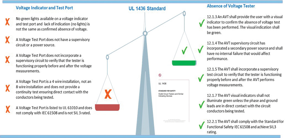
The major difference between a voltage test port and an absence of voltage tester are design, functionality and certification standards. A voltage test port (with our without voltage indication included) is a test device that is designed and tested to UL 61010 and the purpose is to measure voltage.
An absence of voltage tester is designed and tested to UL 1436 and the purpose is to verify the absence of voltage, and UL contains multiple design and test clauses that a voltage test port does not comply with.
There is also the small fact of OSHA’s interpretation – It was stated by OSHA Directorate of Enforcement Programs that:
1910.333(b)(2)(iv)(B) generally does not permit testing a circuit at a point remote from the circuit elements and equipment parts to which the employee will be exposed. A voltage test port is remote from the circuit elements to which employees would be exposed and are therefore disallowed.
If the OSHA provision in 1910.333(b)(2)(iv)(B) generally does not permit testing a circuit at a point remote from the circuit elements and equipment parts to which the employee will be exposed and this disallows permanently mounted test devices such as a voltage test port, then why would OSHA allow a UL approved absence of voltage tester to be used?
Exception 1 to NFPA70E 120.5 Rule 7 states ““An adequately rated permanently mounted absence of voltage tester shall be permitted to be used to test for the absence of voltage of the conductors or circuit parts at the work location, provided it meets all of the following requirements:
(1) It is permanently mounted and installed in accordance with the manufacturer’s instructions and tests the conductors and circuit parts at the point of work;
The point of work is the very circuit elements to equipment parts to which the employee will be exposed and not a point remote from them.
An absence of voltage tester includes a connectivity check each and every time it is used to ensure that all leads are connected at the point of work
Tackling Market Inertia or Distrust
Change is difficult and changing from an approach of using a multi-meter and testing current carrying conductors directly to pressing a button relying on technology faces distrust from the unknown, is the absence of voltage tester safe to use; how do I know it is installed properly; are the results reliable?
Is it Safe to Use an Absence of Voltage Tester?
An absence of voltage tester display unit is door mounted and connected to the control module via a communication cable so that no hazardous voltage is brought to the door.
The absence of voltage tester is installed on the load side of a disconnect switch and there are no connections to the line side.
How Do I Know that it is Installed Properly?
Two sensor leads are connected to each phase and two sensor leads are connected to ground.
Before conducting the absence of voltage test, the supervisory circuit built into the tester verifies that the leads are connected by injecting a signal down each connection.
During the absence of voltage test there are two separate continuity tests to ensure that all leads are connected.
Are the Results Reliable?
As noted earlier the absence of voltage tester will provide three (3) green lights to indicate that the test has been successful and that it is safe to proceed but how do we know that the three (3) green lights are not in error? To answer that, we look to UL 1436 and the following clauses:
| 12.1.6 – The AVT visual indicator shall only illuminate green when all phase-to-phase and phase-to-ground voltages measure less than 3VAC or 3VDC. |
| 12.1.7 The AVT visual indicators shall not illuminate green unless the phase and ground leads are in direct contact with the circuit conductors being tested |
| 12.1.8 – The AVT visual indicator shall not illuminate green if a phase lead is connected to ground or the ground lead is connected to a phase conductor. |
| 12.1.9 12.1.9 The visual indicator shall not illuminate green unless the secondary power source is operational |
| 12.2.1 – The AVT shall comply with the Standard for Functional Safety IEC 61508 and achieve a SIL 3 rating. |
Functional Safety IEC 61508 and SIL 3 (safety integrity level 3) indicate the fail-safe nature of the product. To achieve SIL 3 the average failure in a hazardous condition, that is three (3) green lights incorrectly, has to be less than once in 10,000,000 hours of operation. That equates to one potential failure in more than 1,000 years.
Changing from using a multi-meter to using an absence of voltage tester removes risk, is safer and quicker but if hesitation remains there is the option to mount both a voltage test port and an absence of voltage tester in a single enclosure.
Qualified personnel can use their trusted meter and the test port and then verify the results by waiting 10 seconds and using the approved absence of voltage tester that is labeled and approved to UL 1436 for testing for the absence of voltage.