Severe weather events over the last year or so have resulted in large areas of the country being without electrical power for hours, days, and sometimes weeks. These severe storms have also resulted in significant amounts of structural damage that is somewhat unusual. The structural damage has been due to tornados, high winds, hail, heavy rains, and flooding. While electrical inspectors cannot deal with the building codes that may be inadequate to deal with these new weather events, we can ensure that using available electrical codes and building codes, Photovoltaic (PV) power systems are being installed using these codes and that they are as safe and as robust as possible, both electrically and mechanically.
There are a number of areas relating to good workmanship in the installation of PV systems that deal with the mechanical installation of the PV system, which are not normally looked at closely during an inspection. This article will start with a look at some of the mechanical and structural details that should be addressed closely to ensure that if the building remains structurally sound during a severe weather event, the PV system mounted on the roof of such a building will still perform its intended use. This examination of some structural details will be followed by a discussion of some electrical details that may need more attention.
STRUCTURAL AND MECHANICAL DETAILS
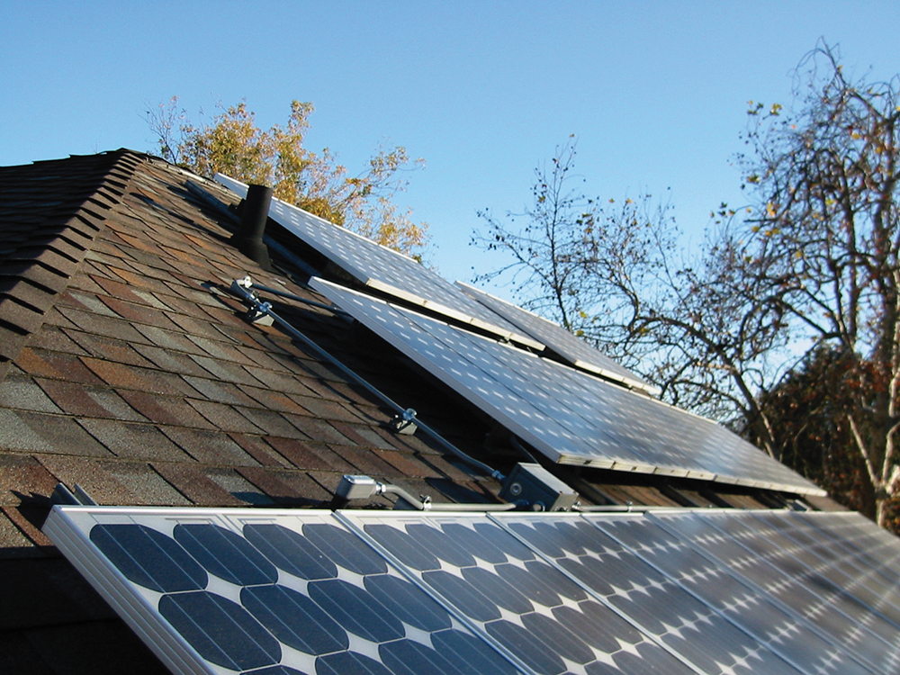
Racking Systems. Frequently commercially available racking systems are used to install PV modules on the roof of a home or commercial building. Underwriters Laboratories (UL) has a Safety Standard (UL 2703) that addresses the construction, mechanical durability, module fastening, and electrical conductivity of listed racking systems. While the National Electrical Code (NEC) does not specifically require that a listed racking system be used, they frequently are (see photo 1).
Racking systems are listed in three separate categories. They can be listed with a fire rating in conjunction with the module fire rating. They can be listed with a bonding, equipment grounding, and electrical conductivity of the racking structure with certain PV modules. And they can be listed with a mechanical means of attachment of specific modules to the rack, such as top clips. Unfortunately, the determination of which of these three areas a racking system listed to UL 2703 applies to a given rack is somewhat difficult to determine. A detailed search of Underwriters Laboratories documents may be required to determine which modules are suitable for use with which racks. The racking listing in the UL documentation is where the search should be started.
Most manufacturers of UL 2703 listed racking systems will have a list of PV modules in the installation instructions that have been evaluated with that racking system for mechanical mounting and bonding and grounding. Additionally, the PV module instruction manual may have a list of racking systems that have been evaluated with that module. If a particular PV module that has been used in an installation is not so listed in the racking manufacturer’s instructions, the PV system installer should be required to provide information as to the suitability of that pairing of module and rack. This issue is yet, another reason why this information should be submitted in the permit application and subject to a plan review.
While the use of an appropriately listed racking system and appropriate PV module will generally ensure that the mechanical installation of the module to the rack and the electrical bonding and grounding of the module to the rack will meet Underwriters Laboratories and NEC requirements, the fastening of the rack to the building structure is not directly addressed as it pertains to a specific on-site roofing system. The racking instructions will cover specific details of how the rack is to be attached to the roof. Generally, this requires sealing any drilled holes against water intrusion and ensuring that bolts or engineered screws penetrate the truss structure and not just the rather thin sheathing on the roof. The PV installer should provide information on how the truss locations were determined.
Another area that should be verified is the wind loading on the truss structure versus the winds expected in the installation area. The racking instructions should detail the various wind velocities that the racking structure can withstand. Local building codes will specify the design wind loads for various structures, but these may not be accurate based on recent weather events.
Also, where required, based on historical and current (most recent) snow loadings, it should be determined that the roof structure, plus the weight of the racking system and the PV modules, will not exceed the structural limitations of the roof. Many roofs throughout the country, due to cost considerations, use the thinnest possible construction methods allowable by the local codes. Some use 7/16-1/2” roof decking. These methods and materials may not be adequate to support the weight of the PV system on the roof, plus snow and/or wind loading.
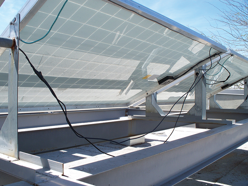
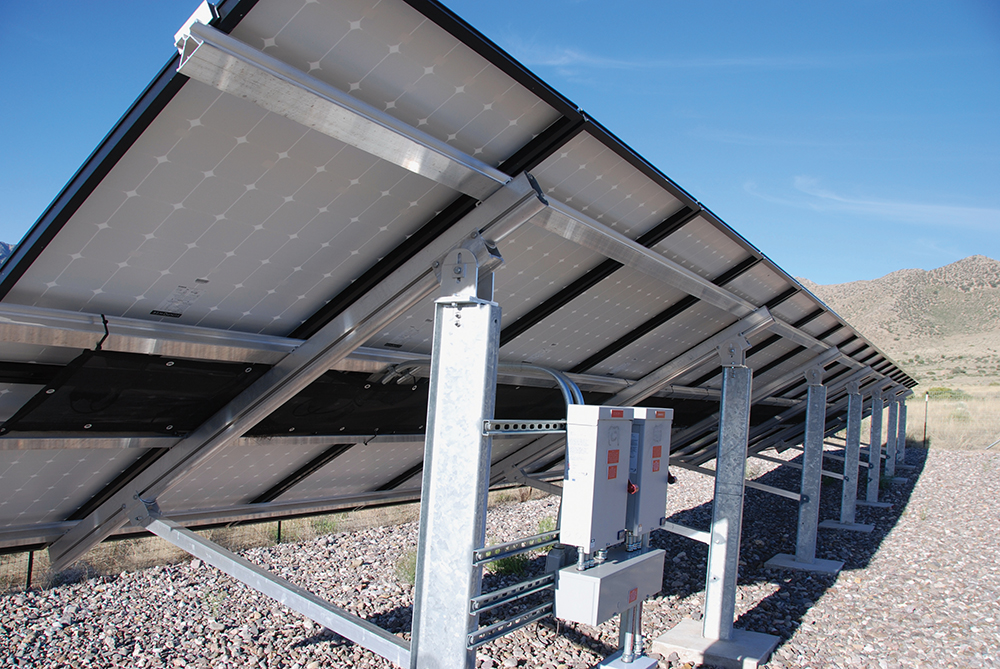
Conductor Protection. The NEC allows exposed single conductors between the PV modules and between the modules and combiner boxes, dc to dc converters, and other similar equipment within or near the array. However, these exposed conductors must be properly secured and protected from increasingly severe heavy rains, ice dams, hail (up to 4” in diameter), and high winds, which can move unsecured cables causing possible insulation damage leading to ground faults and electric shock issues. See photo 2. These exposed conductors should be secured to the racking members near the exit points from module junction boxes and other equipment with a fastening system that should last the life of the PV module—in many cases 30 years or more. See 690.31(C)(1). It has been noted that some plastic wire ties, even some that have been marked and listed as Sunlight Resistant, have not survived more than a few years in the very hot, high solar irradiance climate of the Southwest United States and other similar areas. Specially manufactured metal wire ties and other devices are available for this purpose that will last for many decades in this environment. See photo 3.
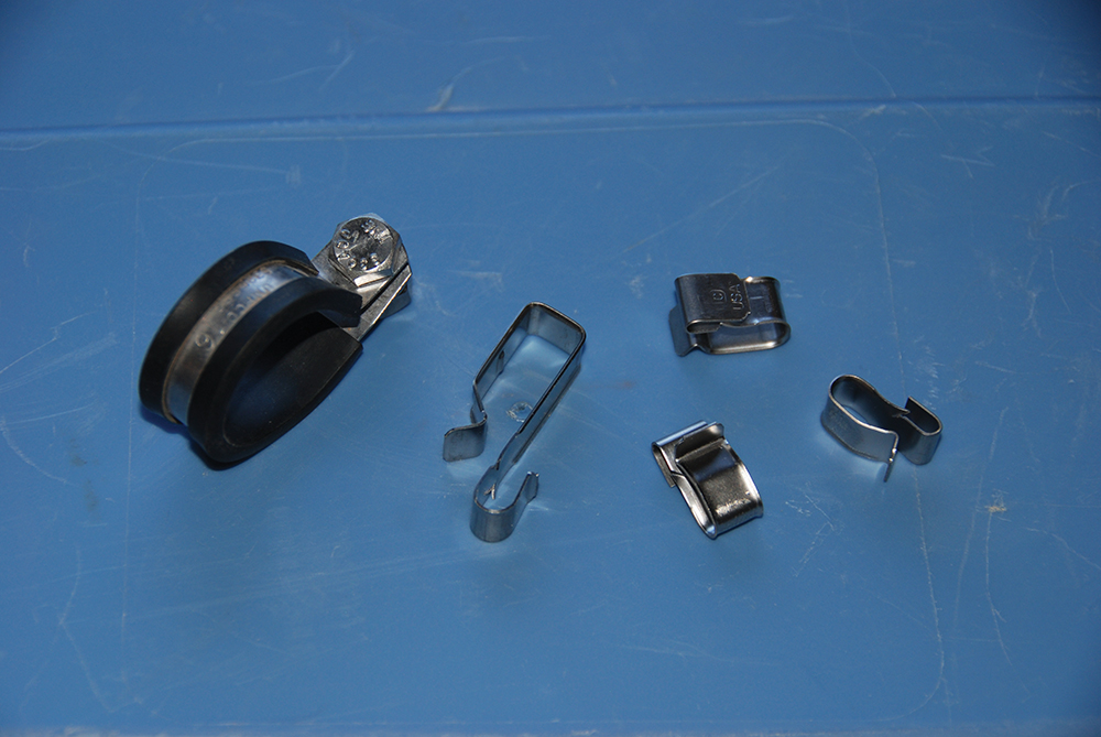
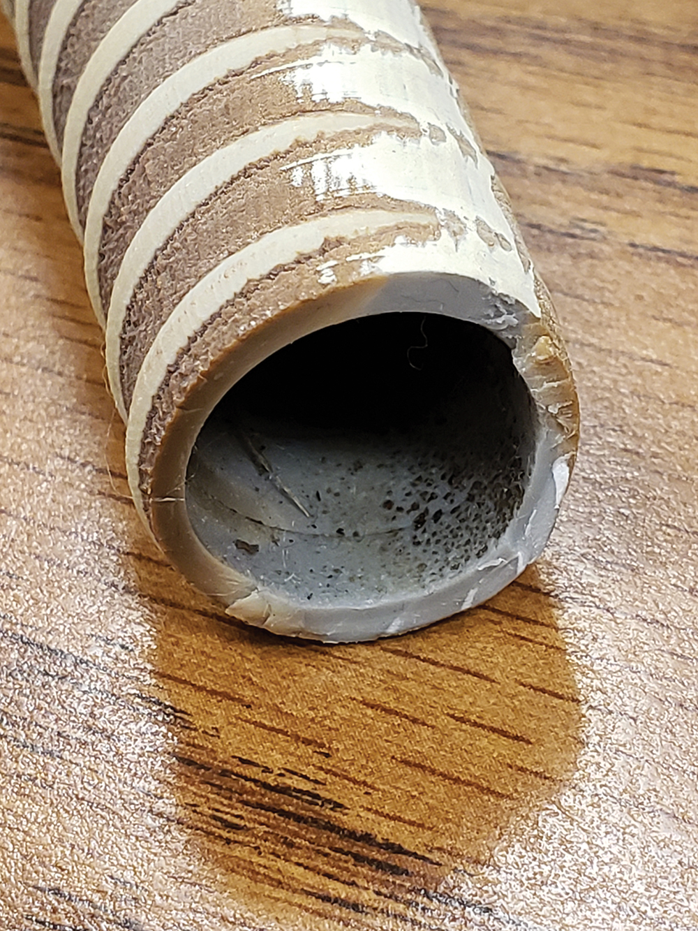
Conduits provide the best protection for rooftop and exterior exposed conductors. These should be securely fastened to the underlying surface so they are not moved by the severe weather events mentioned above. A note: electrical PVC conduits, both flexible and rigid, while listed for 90°C and sunlight resistant, may not be as long-lasting and durable as desired when operated in the exposed, sunny, hot PV environment. PVC conduits exposed to such environments have been found to be blackened, very stiff instead of flexible, and broken in some installations (see photo 4). Consideration should be given before using PVC conduits outdoors under these environmental conditions, which are expected to worsen.
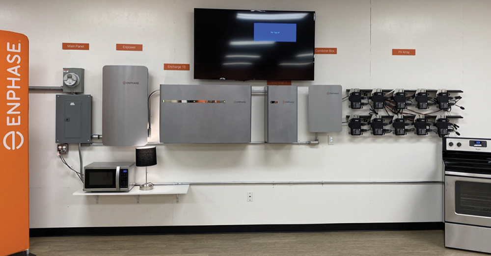
Battery Backed-up PV Systems. Several manufacturers, such as Enphase, Tesla, Panasonic, Generac, and others, are making battery-based/utility-interactive inverter and storage system combinations that are wall-mounted in a rather compact configuration. Some of these systems can weigh over 400 pounds when mounted on the wall (see photo 5). Installation manuals for these systems have detailed instructions for mounting the equipment on a wall without overstressing the wall. These instructions include suggestions to put blocking between the studs of the wall to ensure that the weight is carried uniformly on multiple studs. Of course, this is not possible on finished construction, and an alternative is to use 4’ x 8’ sheets of three-quarter to one-inch plywood fastened to the wall and to all studs as a structural reinforcement to distribute the weight over multiple studs. Another issue that may dictate the use of structural plywood reinforcement is that some of the metal mounting brackets supplied with the equipment do not have predrilled holes that will align for more than two or three adjacent studs when they are on sixteen-inch centers.
ELECTRICAL DETAILS
Battery Backed-up PV Systems. Looking again at the battery-backed-up PV systems, it will be found that although these are factory-engineered units and listed to various UL standards, they are quite complex and allow several optional ways that they can be used. These systems will generally consist of a lithium-ion battery storage module or modules and some sort of overall control device, which is the brains of the system. There may be internal connections that are required inside the various units or devices, as well as connections to external devices and circuits to offer multiple performance options. Various internal electronic controls will require adjustment, frequently using a mobile phone application. The installation and setup instructions for these systems are quite detailed, and additionally, the system installer must make calculations to determine what optional equipment is required to make the systems perform as desired. The optional equipment would include overcurrent devices and their ratings used inside the devices for the various circuits between the internal devices and the external devices in the overall system. Also, the ampacity of the various conductors involved must be calculated. The NEC does not provide detailed instructions on how each of these systems must be installed and connected. Those instructions are found only in the installation manuals, which must be carefully followed so as not to violate the listing requirements of the particular system [See 110.3(B)].
These systems will usually require a plan review process by the AHJ to at least review these manuals to understand the various adjustments that must be made to ensure safe operation.
Supply-side Connections. Article 705.11 has been substantially expanded in the 2020 and 2023 NEC to include significant details concerning supply-side connections to the service. These details should be reviewed and examined for the proper installation of supply-side connections. They refer to numerous other sections of the code for additional requirements. One of these details that may be overlooked is the requirement in Section 230.46 concerning the use of listed power distribution blocks or splicing devices that are marked as suitable for use on the line side of service equipment.
Another area that requires special attention when using supply-side connections is the new requirement (2020 and 2023 NEC) for an “emergency disconnect” in one- and two-family dwelling units in Sections 230.85 and 225.41. The NEC has not yet fully coordinated the requirements of Section 705.11 with Section 230.85 to ensure that the PV system supply side service connection can be installed on the supply side of the service disconnect while remaining on the load side of the service meter to allow proper monitoring. The issue occurs when the emergency disconnect has been installed on the supply side of the meter and is marked “Service Disconnect.” This issue will have to be resolved by possibly moving the meter or moving the Emergency Disconnect to the load side of the meter before making the PV connection.
Load-side PV Connections. Section 705.12 appears to be significantly revised but the actual content and requirements are essentially like those in previous editions of the code with a few clarifications. As in previous editions of the Code, Section 705.12(B) will be commonly used in making PV installations. It has several options, and each requires some specific detailed requirements. In Section 705.12(B)(2) it should be noted that there is a specific requirement that the two sources involved (the service and the PV system output) must be located at opposite ends of the busbar. In other sections of 705.12(B) of the Code, there are no limitations on the placement of the PV sources or the loads. The Informational Note at the end of Section 705.12 says that equipment listed under UL 1741 may have instructions for connections that are not covered by the 705.12 requirements and that the requirements of 705.12 apply where there are no specific instructions in the listed equipment for such connections.
As in previous editions of the Code, Section 705.12(A)(2) dealing with feeders and taps says that where the two power sources (utility and PV) are not at opposite ends of the feeder, the requirements of this section apply. What is implied is that when these two sources are at opposite ends of the feeder, no ampacity changes in the feeder are required because the currents from the two sources oppose each other and do not increase the current at any location in the feeder.
Section 705.28(A) and (B) have been revised for clarity, and additional requirements added. Section 705.28(B)(1) has three exceptions that will require careful reading to apply properly.
DC PV Circuits. In Section 690.4, additional equipment has been added that is now required to be listed.
Section 690.11 concerning arc fault circuit protection has an exception that allows the system to be installed without arc fault protection. However, since PV modules currently are not supplied with metal-clad cables and generally do not have provisions for the connection of metallic conduits, it will be difficult to meet this exception.
The installation requirements for single conductor cables in cable trays have been expanded with additional requirements added in Section 690.31(C) (2).
The requirements of 690.33(C) require some additional attention. They were added in the 2020 NEC and require that if the mating connectors between equipment are not of the identical type and brand, they shall have been listed together for intermatability. While most DC PV connectors are type MC4 connectors, they are made by numerous manufacturers, and while they will plug together, few have been listed for use as mated pairs when made by different manufacturers. This lack of a paired connector listing may represent long-term reliability issues. Will the plating on the pins of the two different connectors be long-lasting? Will the plastics expand and contract at the same rate over the wide variation in operational temperatures? Laboratory tests have indicated connector failures during long-term testing when mated connector pirs have not been from the same manufacturer.
While NEMA and the PV industry are working on a NEMA production standard for a standardized PV DC connector which will specify the size, shape, and various materials and tolerances, this standard has not yet been released. Some manufacturers of dc-to-dc converters, PV rapid shutdown equipment, and similar items are offering their equipment with a selection of the more commonly available connectors that are being used on PV modules.
While the PV Industry is awaiting the NEMA PV connectors standard, the PV installer will have to use some type of workaround, such as installing connectors on external equipment to match, for example, the connectors that come with the module. The AHJ will have to decide whether or not to allow this activity, probably based on the use of the proper tools, manufacturer’s instructions, and workmanship.
Summary
Inspecting photovoltaic power systems requires continuing attention to detail. Each edition of the NEC becomes increasingly more complex as sections are revised for clarity, and additional requirements are added. Also, requirements that are no longer appropriate are removed. Manufacturers of PV equipment are building equipment to requirements established by Underwriters Laboratories Safety Standards. These Safety Standards are revised and updated as new additions of the NEC are released. It behooves local jurisdictions to update their requirements for code compliance to the latest edition of the NEC to avoid conflicts between manufactured equipment and local code requirements.