The need to protect workers from the hazards of arc flash is well understood. The National Fire Protection Association’s Standard NFPA 70E first addressed the issue in its guidelines for safety boundaries and maintenance practices, including personal protective equipment (PPE). However, as electrical environments change arc flash threats need to be reevaluated. Electrical equipment can play an important role in minimizing arc flash hazards. The type of equipment specified, and where in an electrical system it’s installed, can significantly reduce the duration and threat of an arc flash incident.
- A source of possible injury or damage to health.
- A combination of the likelihood of occurrence of injury or damage to health and the severity of injury or damage to health that results from a hazard.
Introduction
While the threat of shock and electrocution from inadvertent contact with energized parts has long been recognized, the arc flash and arc blast hazards have only fairly recently been incorporated into the electrical safety standards. The Occupational Safety and Health Administration (OSHA) enforces electrical workplace safety standards outlined in the National Fire Protection Association’s NFPA 70E: Standard for Electrical Safety in the Workplace®.
Basic compliance to the requirements of NFPA 70E is established through a six-step process:
- Develop and audit electrical safe work practices policy
- Conduct an arc flash risk assessment to evaluate the likelihood of occurrence and severity of arc flash hazards
- Follow strategies to mitigate and control arc flash hazards
- Conduct regularly scheduled safety training and audits for all electrical workers
- Maintain electrical distribution system components
- Ensure adequate supply of personal protective equipment (PPE) and proper tools
Companies can take additional steps to reduce the potential for an arc flash. The remainder of this paper will focus on mitigating arc flash hazards, specifically engineering controls.

What is Arc Flash Mitigation?
According to Webster’s dictionary, mitigation is defined as, “to make milder, less severe or less violent”. When applied to electrical workplace safety, arc flash mitigation involves taking steps to minimize the level of hazard and/or the risk associated with an arc-flash event.
ANSI Z10-2012, Occupational Health and Safety Management Systems, released a hierarchy of arc flash mitigation controls, as shown in Figure 2.
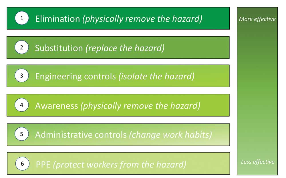
The most effective arc flash safety programs look to incorporate “safety by design.” Though not as effective as substitution or elimination, the goal of engineering controls is to reduce the degree of hazard. Administrative controls and warnings are less effective because they rely on workers following proper procedures and safe work practices.
The engineering controls covered in the following pages will either:
- Reduce arc flash energy to a level where permitted tasks can be performed, or
- Locate the worker so that he/she is not subject to harm.
Reduce Arc Flash Energy Levels
Arc flash reduction systems do not eliminate the electric shock hazard of working on or inside energized equipment. The amount of arc flash energy reduction will be determined by an engineering analysis.
The goal of reducing arc flash energy levels is to reduce the severity of the potential arc flash hazards to which a worker may be exposed. Personal protective equipment (PPE) is required when an arc flash energy reduction system is employed, but the level of PPE may be reduced.
Obviously, too little PPE can increase the worker’s exposure to burns and injury. Too much PPE can also have a detrimental effect such as heat stress, loss of motion and visibility, and carelessness due to rushing the task at hand.
Energy = Volts x Amps x Time
Faster clearing time = Lower Energy
The Role of the Circuit Breaker or Fuse in Lowering Arc Flash Energy Levels
Why is a circuit breaker or fuse always considered in the arc flash analysis? Because arcing time is the key determining factor for arc flash energy. Per the equations in IEEE Std. 1584-2002, arc flash incident energy varies linearly with time. If the duration of the arcing fault doubles, the available energy doubles; halve the duration and you cut the energy in half.
Since incident energy is proportional to arcing time, the use of faster-acting devices is key. As a result, proper selection of overcurrent protective devices – in particular, selecting devices that will quickly clear arcing faults from the power system – is a powerful mitigation strategy
Over-Current Protective Device (OCPD) Coordination Study
An OCPD coordination study optimizes the protective device setting for reliability and arc flash protection. While an OCPD study is not a requirement of an arc flash analysis, it is recommended to have this study completed as a component of an arc flash analysis.
The OCPD coordination study will determine if minor adjustments in circuit breaker (or other over-current protective device) settings can lower incident energy levels. However, settings must be chosen to properly protect equipment while still allowing for normal load currents and routine temporary overcurrents (e.g., motor starting current) to flow without causing a trip.
Specialized Relaying, Such as Optical Technology
Quickly clearing faults is a key to arc flash mitigation. Circuit breaker or relay settings near the source of power may have significant time delays to allow for coordination of downstream devices. A relatively new way to address this issue is to use relays that detect the presence of arcing faults by looking for the flash of light associated with the arcing fault in addition to the characteristic current flow.
However, for an arcing fault to be detected, both the high current and a burst of light must exist. When both conditions are present, the optical relay can operate very quickly to clear the fault. This typically occurs through the operation of an overcurrent protective device. Alternatively, the optical relay can activate a shorting switch that creates a bolted fault that clears the arc even more quickly than a circuit breaker could operate. Optical relays can also be used as the protective relay in a virtual main configuration.

Virtual Main Arc Flash Mitigation System
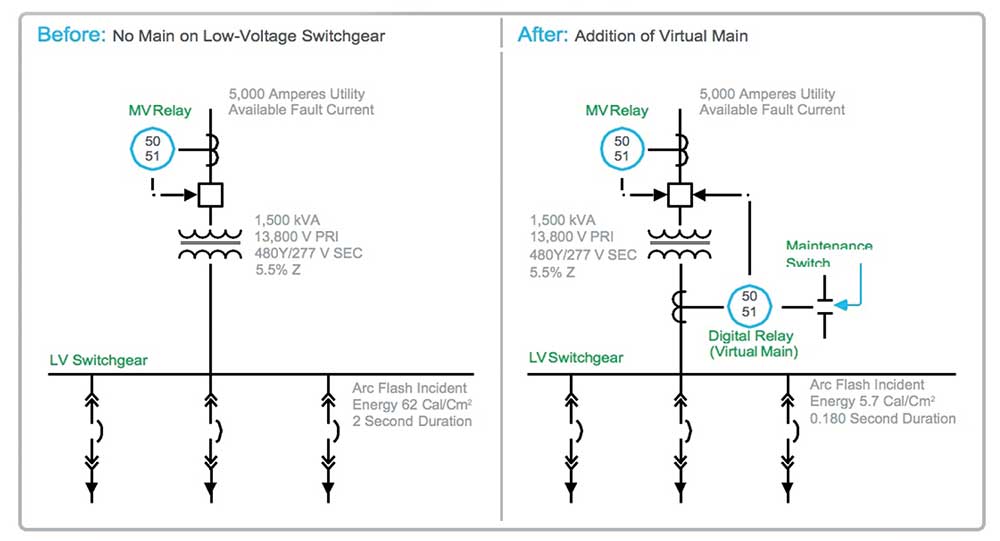
Switchgear and switchboards can be subjected to dangerous levels of arc flash incident energy when fed directly from a power transformer. The addition of a virtual main system reduces the arc flash energy on the entire switchgear, including the main incoming section. Digital relay and overcurrent sensing are added to the low-voltage side of the service transformer and are designed to trip an existing upstream fault breaking device, often a medium-voltage circuit breaker or other vacuum interrupter. This mitigation solution can take one of two forms:
- A maintenance selector switch, which temporarily lowers the instantaneous short circuit current setting. The maintenance setting lowers the available arc flash incident energy and temporarily forfeits selective coordination.
- Zone-selective interlocking with downstream branch circuit breakers in the switchgear eliminates the need for the maintenance selector switch. Arc flash energies can be permanently reduced with zone-selective interlocking.
Before and After One-Line Diagrams
An arc may propagate to the supply side of all devices in the same enclosure. That is why virtual main systems trip the upstream device.
The following arc flash mitigation solutions remove a worker from the location of, or place a barrier between, the worker and exposed energized parts:
Remove Workers from Harms Way
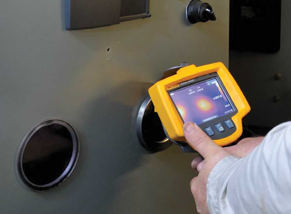
Infrared Viewing Windows
Having infrared (IR) windows permanently installed into electrical equipment enables IR scans to be performed without exposing the worker to hazardous energy. IR windows are made of a glass-like material that is transparent to infrared rays and allows hot spots to be registered by a thermographic camera. They also facilitate permanent access for inspection of electrical components without disturbing operations.
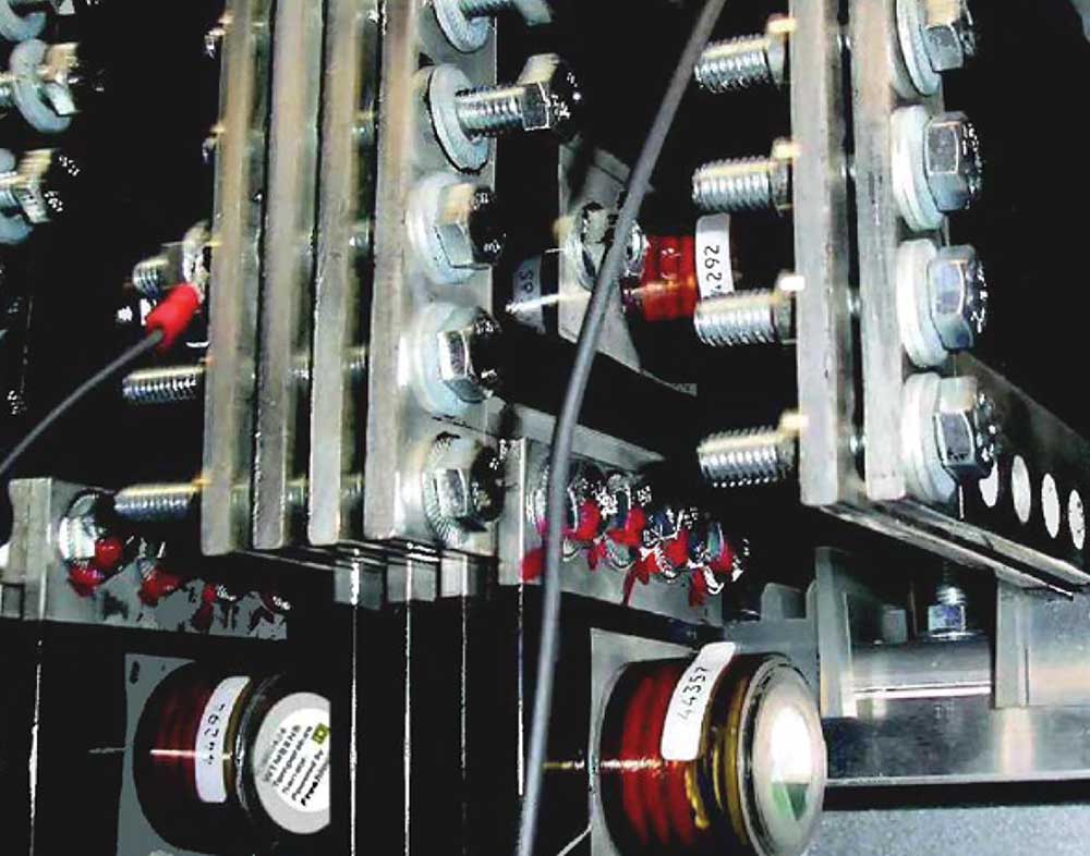
Online Temperature Monitoring
Online temperature monitoring, via wireless sensors, provides 24/7 access to critical connection points where traditional thermography cannot be used. This technology evaluates the equipment’s current condition without exposing workers to energized parts since equipment covers do not have to be removed. The sensors are installed during a planned outage and can be used in equipment with high arc flash ratings without a risk of danger to personnel or equipment.
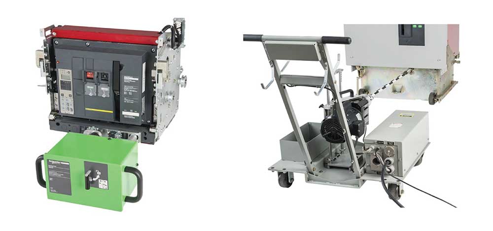
Remote Racking System
A remote racking system (RRS) allows circuit breaker racking operations to be performed via a control panel located away from the cell, removing the operator from manual contact with the circuit breaker. If the operator controlling the RRS is located outside the arc flash boundary, the need for PPE is eliminated.
Conclusion
Electrical hazards are a significant safety and financial risk for electrical workers and their employers. OSHA mandates that work on electrical equipment must be performed in a manner that does not expose the worker to undue risk of injury. Complying with the safe work practices dictated by NFPA 70E and implementing arc flash mitigation strategies through engineering controls will enhance workplace safety for employees and reduce the financial risk for your company.
Reprinted with permission by Schneider Electric. “Mitigating Arc Flash Hazards.”