
Photovoltaic (PV) module prices continue to decrease, and racking systems are reducing the labor required to install PV systems, leading to larger PV systems and increasing numbers of supply-side PV system connections. However, as appliance and HVAC system efficiencies increase, load-side PV connections associated with smaller PV systems will be with us in great numbers. Having said that, battery backup systems, partial load, and whole-house are becoming increasingly common in many of these load-side connections.
The Basics
A load-side PV connection is an electrical connection of the PV system output (power source) to a circuit in the building or dwelling, which is on the load side of the main service disconnect. The circuits that may be affected by this load-side connection are numerous and require careful assessment. Any circuit, whether it be a busbar or a conductor (feeder), that has the possibility of carrying currents from both the utility source (through the main breaker) and the PV system may have to comply with the requirements of Section 705.12 in the National Electrical Code (NEC).
A number of main service entrance equipment panel boards or load centers have somewhat unique configurations compared to the standard configuration of a single main circuit breaker connected to a busbar with a set of load circuit breakers attached to that busbar.
Six Main Breakers. One common configuration is a service entrance panel board, which has not one main breaker but two to six main breakers. This configuration is no longer permitted under the 2020 NEC; each new service must have only a single main breaker. Each of these six (and sometimes fewer) main breakers is connected to a specific load such as an air conditioner, water heater, electric range, electric dryer, or swimming pool circulating pump. At least one of these main breakers is connected to a subpanel with numerous circuit breakers for load circuits like lighting and electrical receptacle outlets.
A utility-interactive PV system ac output connection to one of these unused (open) main breakers would be considered a supply-side connection since there is no single main breaker ahead of any of the six main breakers.
Ranch Panel. In some parts of the country, a service entrance panel known as a ranch panel is used that has, for example, two 200-ampere or possibly even two 300-ampere main breakers. One of these main breakers is connected directly to a busbar in this service entrance panel, which has the full set of load breakers for various load circuits throughout the building. The other main breaker is reserved for a remote subpanel, possibly in a barn or other outside structure. In some cases, the second circuit breaker is unused, and a PV system is connected to it. Again, since there is no additional main breaker ahead of these two main breakers, this becomes a supply-side connection. And the 2020 NEC no longer permits the installation of these types of panels.
After determining that the PV system connection will actually be made on the load side of the main service entrance breaker (or fused disconnect), there are numerous locations where that PV system connection can be made, but in each situation, all circuits on the load side of the main breaker must be assessed to assure that with the PV connection, all Code requirements in Section 705.12 are met. Generally, circuits in a load center that are connected only to loads are protected by the circuit breaker supplying that circuit and would not be affected by PV currents (or currents from other sources-possibly batteries) connected to another part of the electrical system.
125%. Recent editions of the NEC have allowed the use of 125% of the rated output of the PV utility-interactive inverter power source in conductor and busbar calculations. This is the same numerical 125% that is used throughout the Code to ensure that conductors and devices including overcurrent protective devices are not operated at more than 80% of their rating on a continuous basis. In past editions of the Code, the requirement was to use the rating of the PV inverter output circuit breaker to make subsequent busbar and conductor calculations. By allowing the use of 125% instead of the breaker rating, we get a slight advantage on the more complex systems since this number may be slightly smaller than the rating of the required circuit breaker, which is subject to round up to the standard values.
Looking Deeper
First, establish which of the many load circuits protected by a circuit breaker or subpanels protected by the main breaker, which have no PV source or other power source connections downstream of those circuit breakers, are not subjected to any potential overload from PV system outputs. Then, the circuits that are subjected to these combinations of utility currents and PV source currents can be examined. Section 705.12 gives substantial amounts of information needed to make these determinations. It must be kept in mind that not only potential overloads must be dealt with but also short-circuits on these various conductors and busbars.
Section 705.12(A) requires that a dedicated circuit breaker or fusible disconnecting means be connected to the output of each source. If there are multiple sources, each source shall have a dedicated overcurrent protection device at its output. Although not specifically addressed in the code, multiple sources, each with a dedicated overcurrent device, may be combined using the various requirements and Section 705.12 into a single multi-system output where a single circuit breaker may be used to connect the multiple sources to the existing electrical system. And, where multiple sources are involved, they may be separately connected to the existing system if all NEC requirements are met, such as the PV Rapid Shutdown system requirements (690.12).
Feeders [705.12(B)(1)]. Section 705.12(B) is where the details of the requirements for busbar or conductor ampere ratings are determined. And, in this section, the 125% factor for calculations is mentioned. Feeders are addressed in subsection (1). Also required by Section 690.8, where the power source output is connected to a feeder, that feeder must have an ampacity equal to or greater than 125% of the power source output circuit current. This is a minimum requirement since utility currents are also involved. When the connection from a power source is made to an existing feeder, that connection may occur at the beginning of the feeder, at the end of the feeder, or at someplace in between these two locations.
Where the connection is made at the beginning of the feeder, the entire feeder and any downstream equipment are subjected to the current available from the utility plus 125% of the power source’s output current rating. The available current from the utility will be determined by the rating of any circuit breaker limiting current to the feeder from the utility.
Although not specifically mentioned in the 2020 NEC (hopefully, it will be in the 2023 NEC), where the source is connected at the load end of the feeder, there is no impact on the ampacity of the feeder. Of course, this is providing that the feeder has an ampacity of 125% of the rated output of the power source and was also properly rated and protected in the original system. The reason for this is that any currents from the power source will be either absorbed by the loads connected to the feeder or in the absence of any loads or loads smaller than the source currents, the currents from the source will flow back towards the utility and oppose any currents from the utility. The currents from these two sources cannot add at any place on the feeder. Therefore, there is no requirement to increase the ampacity of the existing feeder.
Source connections at some location between the beginning of the feeder and the end of the feeder are a little more complex, as noted in subparagraph (1). As described above, the section of the feeder between the beginning of the feeder and the source connection does not require any changes. The source currents are either fully absorbed by the loads connected to the feeder or with lesser loads or no loads; the currents flow back towards the utility source and actually reduce currents on the feeder. However, the section of the feeder from the power source point of connection to the end of the feeder is potentially subjected to the sum of the available currents from the utility plus the currents from the power source.
Sections 705.12(B)(1) a. and (1) b. provide two options. Subsection a. allows that existing portion of the feeder from the point of connection of the source to the end of the feeder to be replaced with a conductor having an ampacity of not less than the sum of the available utility currents to the feeder plus 125% of the rated power source output current. This same increased current rating/ampacity would also apply to any unprotected busbar connected to the end of the feeder. Of course, the main breaker protected busbar connected to the end of the feeder would presumably have a breaker and busbar rating equal to the existing available utility currents to that feeder. It would protect anything downstream of that breaker from the power source currents added to utility currents. But we must keep in mind the potential for overloads and short-circuits in that section of feeder that is subjected to both the sum of the available utility currents and the power source currents, hence the requirement to increase the size of that portion of the feeder. An overcurrent device at the end of the feeder would not provide full protection for the feeder.
Subsection b. allows the protection of that portion of the feeder from the point of connection of the power source to the end of the feeder by placing an overcurrent protective device at the point of connection on the load side of that point of connection with a rating equal to the ampacity of the existing feeder. If additional loads were connected to the feeder at some point in the future, an overcurrent device at this location would protect the feeder from any additional source currents being added to the available utility currents.
Taps [705.12(B)(2)]. When a power source is connected to a feeder, any new or existing taps to that feeder must be carefully examined. The tap rules in 240.21 (B) were designed with one power source (usually the utility). Section 705.12(B)(2) allows the tap rules to be used where the sum of 125% of the power source rated output current plus the rating of the overcurrent device protecting the feeder is used as the single current source in the tap rule calculations. The rules only determine the length and ampacity of the tap conductor. Any effect on the feeder of connecting the additional power source must be addressed, as shown in the preceding sections.
Where a tap already exists on the feeder and a power source connection to that feeder is planned, the existing tap must be recalculated as described above using the sum of all available sources. The tap conductor ampacity may have to be changed.
Busbars [705.12(B)(3)]. With the exception of a busbar fully protected by a main overcurrent protective device with no sources after that overcurrent protection device, any busbar that is subjected to both utility currents and power source currents must comply with one of the requirements in the subsections of 705.12(B)(3). There are many creative ways that this section’s requirements can be applied in the connection of PV or other power source circuits to existing load side circuits.
Subsection (1) requires that the sum of the rating of the overcurrent device protecting the busbar plus 125% of the rating of the power source output not exceed the rating of the busbar. This is fairly straightforward. In some cases, the main breaker has been used with a higher rated busbar leaving the capacity available to add a source circuit output anywhere on the busbar. Alternatively, where load calculations permit and the equipment can accept an interchangeable main circuit breaker, the main circuit breaker may be reduced in rating. The difference between the busbar rating and the new main circuit breaker can serve as an allowance for connecting the output of the power source. And this requirement does not restrict the connection of the power source to the busbar at any particular location on that busbar.
Subsection (2) is the long-standing 120% rule. This section applies to cases where the connected power source is made at the opposite end of the busbar from the main circuit breaker protecting the busbar. The power source must be connected at the opposite end of the busbar to prevent the busbar from being overloaded no matter how much load is connected to the busbar between those two current sources. There is no place on the busbar where the utility current from the main breaker can add to the current from the power source.
As an aside, the 120% allowance (the sum of main breaker plus 125% of the power source rated output cannot exceed 120% of the busbar rating) is based on thermal considerations. Load centers are tested according to standards established by Underwriters Laboratories (UL), with the main breaker installed and two load breakers installed at the top of the panel with ratings equal to the main breaker. The panel is heated to a temperature of 40°C (104°F) and rated current is supplied through the main breaker and out through the load breakers. The circuit breakers are thermal-magnetic, and they generate heat when current flows through them. This heat is added to the 40 °C temperature of the load center/panel board, and the breakers must not trip while carrying 100% of their rated current. It was determined in the early days of Article 690, Solar Photovoltaic (PV) Systems, in the NEC that these panels or load centers and the circuit breakers could withstand slightly increased internal temperatures generated by an input current from an added power source and the current from added load currents that were equal to the added power source currents.
There are additional requirements in this subsection that ensure that the busbar is sized to carry the connected loads per Article 220. A permanent warning label with wording like that below or its equivalent shall be located adjacent to the power source circuit breaker.
WARNING:
POWER SOURCE OUTPUT CIRCUIT CONNECTION –
DO NOT RELOCATE THIS OVERCURRENT DEVICE.
Subsection (3) is a relatively new requirement. It requires that the sum of all overcurrent devices both for power source supplies and for loads, excluding the main circuit breaker (or the rating of the overcurrent protective device protecting the busbar), shall not exceed the rating of the busbar. Furthermore, the rating of the main overcurrent device protecting the busbar shall not exceed the rating of the busbar. A permanent warning label must be installed on the distribution equipment.
WARNING:
THIS EQUIPMENT FED BY MULTIPLE SOURCES.
TOTAL RATING OF ALL OVERCURRENT DEVICES
EXCLUDING MAIN SUPPLY OVERCURRENT DEVICE
SHALL NOT EXCEED AMPACITY OF BUSBAR
It should be noted that this requirement allows the connection of the power source circuit breaker(s) anywhere on the busbar. The reasoning is that if you limit the total ratings of all overcurrent devices to be less than or equal to the rating of the busbar, there is no combination of sources or loads that can overload the busbar.
An Example
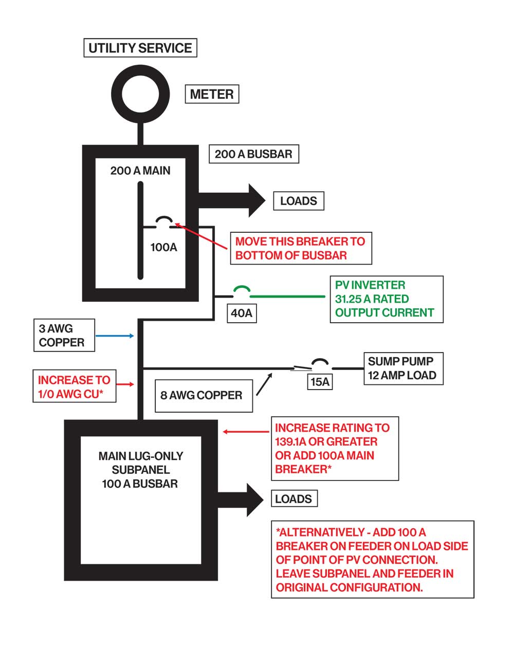
The requirements above can be best summarized by analyzing the sample circuit in figure 1.
The existing system (shown in black) has a 200-ampere service entrance panel with a busbar rating of 200 amps and a 200-ampere main breaker. There are load breakers on this panel totaling 325 amperes that have been sized based on Article 220 load calculations for the dwelling.
One of these breakers, located near the middle of the busbar, is rated at 100 amperes and connects to a 240V, 3 AWG THWN-2 copper feeder (115 amps at 30*C and 100 amperes with 75°C terminations) running to a main-lug-only 100-amp subpanel a seventy feet away. The feeder has an existing tap for an added sump pump that draws 12 amps when running. The tap conductors run 20 feet to a two-pole 15-ampere breaker at the sump pump and are 8 AWG THWN-2 copper conductors (55 amperes at 30°C and 50 amperes with 75°C terminations) and meet the requirements of 240.21(B)(2).
The new PV system that is to be connected to the existing wiring system has a utility-interactive inverter with a rated output of 31.25 amperes at 240 volts (7500 watts), and the manufacturer’s specifications allow a maximum overcurrent device on the output of 50 amperes.
For this installation, an overcurrent device (circuit breaker) of 40 amperes has been used (1.25 x 31.25 =39.1 amperes), and the inverter output circuit conductors will be 8 AWG THWN-2 copper conductors (ampacity of 55 amperes at 30°C and 50 amperes with 75°C terminations). The PV power source output circuit is connected to the feeder about 40 feet from the main service panel. The 40-ampere breaker on the power source output circuit will be connected on this circuit near the point of connection to the feeder.
The examination of the ac connections for the PV system addition will start at the service entrance panel. With the 100-ampere breaker for the feeder located near the middle of the service panel, none of the Code requirements for the service entrance busbar can be met.
However, moving load breakers around on this busbar and moving the feeder 100-amp breaker to the position on the busbar furthest from the main breaker (shown in red) will allow 705.12(B)(3)(2) to be used since the 40-ampere PV allowance on a 200-ampere busbar with a 200 ampere main breaker is met. The 125% PV output is only 39.1 amperes.
The feeder ampacity will require no changes from the 100-ampere breaker to the point of the PV system connection because any currents from both sources will be in opposition. However, the feeder ampacity of 115 amperes (100 amperes with 75°C terminations) from the point of connection to the remote subpanel is insufficient to meet Code requirements. The ampacity of that portion of the feeder must be increased to 100 + 39.1 = 139.1 amperes requiring 1/0 AWG THWN-2 copper conductors (170 amperes at 30°C and 150 amperes with 75°C terminations) to meet 705.12(B)(1)(a).
Note that if the feeder conductor is increased in size as allowed by 705.12(B)(1)(a), then either the 100-ampere subpanel rating must also be increased to at least 139.1 amperes, or a 100-ampere main breaker must be installed in the subpanel to protect the subpanel busbar from excess currents should the loads ever be increased above 100 amperes.
Alternatively, a 100-ampere circuit breaker can be installed on the feeder conductors at the point of PV system connection on the load side of that connection per 705.12(B)(1)(b). In this case, no increase in the ampacity of the conductors or the subpanel rating would be required. The addition of the breaker at this point may be the easiest and cheapest solution.
The existing tap conductor needs to be recalculated to see if it still complies with the tap rules in 240.21(B)(2). The available currents that must be used in the tap rule are now 100 + 39.1 = 139.1 amperes). One-third of this number is 46.3 amperes, and the 8 AWG copper THWN-2 conductors with an ampacity of 55/50 amperes still meet tap rule requirements.
Due to space limitations, Sections 705.12(B)(4) through (6), 705.12(C), and 705.12(D) will be covered in a subsequent article.
Summary
Article 705 gets more complex with every edition of the NEC. However, it is clearly written and provides increasingly useful guidance for those willing to read it carefully and work out examples to illustrate its various points.