In my opinion, two locations within the power distribution system present unique challenges for the electrical worker, service entrance equipment and the equipment directly on the secondary of a transformer. The 2020 version of the NEC just took a leap forward for at least one of these two locations with changes to a rule that has been a long-standing requirement for many years – the six (6) disconnect rule found in 230.71. This discussion would be amiss if we covered the changes in 230.71 without touching on the changes in 230.62(C), barrier requirements for service equipment because the journey for that which we see in 230.71 began due to NEC-2017 changes requiring line-side barriers for service panelboards.
Before we move forward in this area, please recognize that what is learned about the hazards in service equipment and the new requirements for these locations can be used to help increase safety for similar applications elsewhere. A prime example is the equipment found directly on the secondary side of power distribution transformers regardless of their location in the system. As this discussion progresses, we will close with how this information can be leveraged in other than service equipment.

The Beginning
To understand the journey to the changes in the 6-disconnect rule seen in NEC 2020, we must first look back to NEC 2017 with the changes made in 408.3, and more specifically, the exception to 408.3 that had to be created. Section 408.3 as part of NEC-2017 reads as follows
408.3 Support and Arrangement of Busbars and Conductors.
(A) Conductors and Busbars on a Switchboard, Switchgear, or Panelboard. Conductors and busbars on a switchboard, switchgear, or panelboard shall comply with 408.3(A)(1), (A)(2), and (A)(3) as applicable.
(1) Location. Conductors and busbars shall be located so as to be free from physical damage and shall be held firmly in place.
(2) Service Panelboards, Switchboards, and Switchgear. Barriers shall be placed in all service panelboards, switchboards, and switchgear such that no uninsulated, ungrounded service busbar or service terminal is exposed to inadvertent contact by persons or maintenance equipment while servicing load terminations.
Exception: This requirement shall not apply to service panelboards with provisions for more than one service disconnect within a single enclosure as permitted in 408.36, Exceptions 1, 2, and 3.
The above exception language generated questions and concerns about the safety of existing practices for service equipment. This exposed the safety concerns of equipment constructed such that a line-side barrier is not practicable, specifically panelboards, with 6 disconnects installed within.
NEC-2020 has recognized the importance of these barriers and moved this barrier requirement into Article 230 for services. This new requirement can be found in 230.62(C) titled “Barriers.” This action expanded the barrier requirement to all service entrance equipment and reads as follows:
230.62(C) Barriers.
Barriers shall be placed in service equipment such that no uninsulated, ungrounded service busbar or service terminal is exposed to inadvertent contact by persons or maintenance equipment while servicing load terminations.
Note that the exception previously a part of 408.3 has been removed, which is indeed at the heart of the changes found in 230.71 of NEC 2020. The significance of this can only be realized once we understand what the hazards are at this location in the power distribution system.
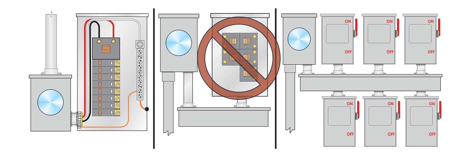
An example of a panelboard with a line-side barrier installed is shown in figure 1.
Understanding The Hazards
The safety concern for this type of equipment — service panelboards with provisions for more than one service disconnect within a single enclosure — is real and had to be addressed at some point in the history of the NEC. The hazards for this equipment include but are not limited to the following:
- The only way to de-energize this service equipment is to call the utility to disconnect the service.
- When six disconnects are in the same enclosure, the act of turning off all of the disconnects provides no level of isolation of power for the electrical worker as the energized common bus will remain exposed unless disconnection at the utility has been performed.
- Incident energy is high because the only upstream OCPD is on the line side of the utility transformer sized to handle inrush current, which will not open quickly on downstream arcing currents
- When the deadfront of the panel is removed, the electrical worker is looking directly at exposed copper or aluminum unprotected bus. The likelihood and severity of an electrical safety event are high for the electrical worker.
The hazards of shock and arc flash are two real hazards electrical workers face every day. Establishing an electrically safe working condition and reducing incident energy relies on upstream overcurrent protective devices and/or switches. Regarding service entrance equipment, the electrical worker doesn’t have direct access to the upstream overcurrent protective device, and the upstream overcurrent protective device is in a location in the distribution system where arcing currents are low enough that clearing times are long. Justified energized work in this equipment presents a real safety challenge to the electrical professional.
Outside of the obvious concerns of shock, an understanding of an arc flash event within an enclosure should be understood to fully comprehend the electrical hazard. Should an arc flash event occur in service entrance equipment, even those with a main overcurrent protective device, the enclosure experiences a rapid release of a plasma cloud that can quickly escalate the event to the lineside lugs of a panel with a main or the main bus of the panel for those without a main. This “lineside propagation” of the arc flash places the clearing time solely in the hands of the upstream overcurrent device.
From Old to New
It was in 1937 that the NEC began the journey into permitting up to six services. Historical documents illustrate this decision as follows:
“Paragraph (c) of Section 401 of this chapter is to be amended by added text to allow for special permission to have more than one set of service conductors run to a single building having a multiple occupancy.”
There were other historical decisions made at this time, including changes in Section 405 that permitted the utility meter, if installed outdoors, to be placed ahead of the service switch and the service fuse. In addition, this edition introduced the structure of the NEC, most of which is what we still know today.
“The main body of the rearranged Code is set forth in ten Chapters as our Appendix indicates. Chapters 1 to 4 are of general application. Chapters 5, 6, and 7 apply to special occupancies or equipment and to other special conditions. Their provisions, as is stated in the Introduction, are supplementary to or amendatory of the general rules. All previous editions of the Code have resorted to this method of avoiding repetition in text. Chapter 8 deals with communication systems–radio and signaling. Chapter 9 will contain only tables and diagrams with necessary cross-references to the rule material of the previous chapters. Chapter 10, similarly to Chapter 9, is a collection, but instead of tables and diagrams is of requirements for details of construction of materials and equipment rather than of installation or appropriate use.”
In 1937, the change to permit more than one service recognized that having one disconnect for a structure may not be the safest approach. The apparent discussions at that time revolved around one disconnect to some structures that would kill power to elevators and other important items within the structure, causing other types of safety concerns. The 1937 report on changes says the following with this regard.
“The changes in the regulations as to service conductors and service entrance equipment register increasing recognition and acceptance of the view that the fire department no longer (if it ever was the practice) proceeds immediately when responding to an alarm of fire to the basement to cut off all current and put premises into darkness and prevent use of elevators or other important aids to their operations. In many buildings, the quantity of electricity used makes the “single-stroke” opening of a disconnect for the entire supply a dangerous if not physically impossible operation. In smaller premises, diversity of use and kinds of supply employed may make a single disconnect undesirably complicated and perhaps hazardous.
A corollary to this development is the subdivision of overcurrent protection and the omission, for some applications, of a single unit of a rating corresponding to the capacity of the service conductors.”
New changes found in 230.71(B), Two to Six Service Disconnecting Means, is changing what the electrical industry has known and used for many years and now provides options for providing a structure with six service disconnects. None of these options permit the installation of a panelboard with six disconnects within. In my opinion, this is a historic moment for the NEC as it has changed a practice that has been in place for more than 80 years.
The options provided for in these installations include the following:
(1) Separate enclosures with a main service disconnecting means in each enclosure:
Examples of applications meeting this option could include fusible switches. Some could make the argument that a six panelboards with a main would be six separate enclosures with a main service disconnect in each enclosure, which leads us to the next option.
(2) Panelboards with a main service disconnecting means in each panelboard enclosure
This option is the item that specifically removes the ability to have a panelboard without a main. This item tells us that a service panelboard must have a main service disconnecting means.
The next option addresses switchboards, and in my opinion, it is very straight forward.
(3) Switchboard(s) where there is only one service disconnect in each separate vertical section where there are barriers separating each vertical section.
And finally, that last option addresses two separate types of service equipment, notably switchgear and metering centers.
(4) Service disconnects in switchgear or metering centers where each disconnect is located in a separate compartment.
It is option 4 that, in my opinion, may see more modifications moving forward into the next version of the NEC. The first step that could be made to improve this item is to separate switchgear from metering centers as, after all, the new Informational Note 1 notes that metering centers are actually addressed in UL 67, which is the UL standard for Panelboards. One could make an argument to include metering centers as part of option 2 which addresses panelboards or address this equipment as a new option 5. The NEC is like a fine wine. It just keeps getting better with time.
These changes accommodate the requirements found in 230.71, as noted above facilitating the barriers of line-side service conductor terminations.
Closing
The changes we see at service equipment are all about reducing the likelihood and severity of electrical hazards. It facilitates the application of line-side barriers, which helps with both aspects of electrical hazards of arc flash and shock.
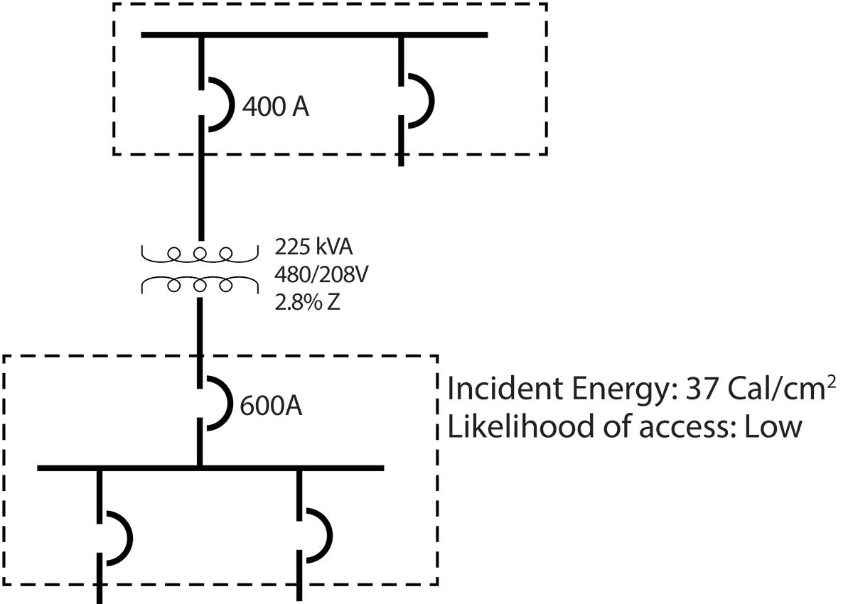
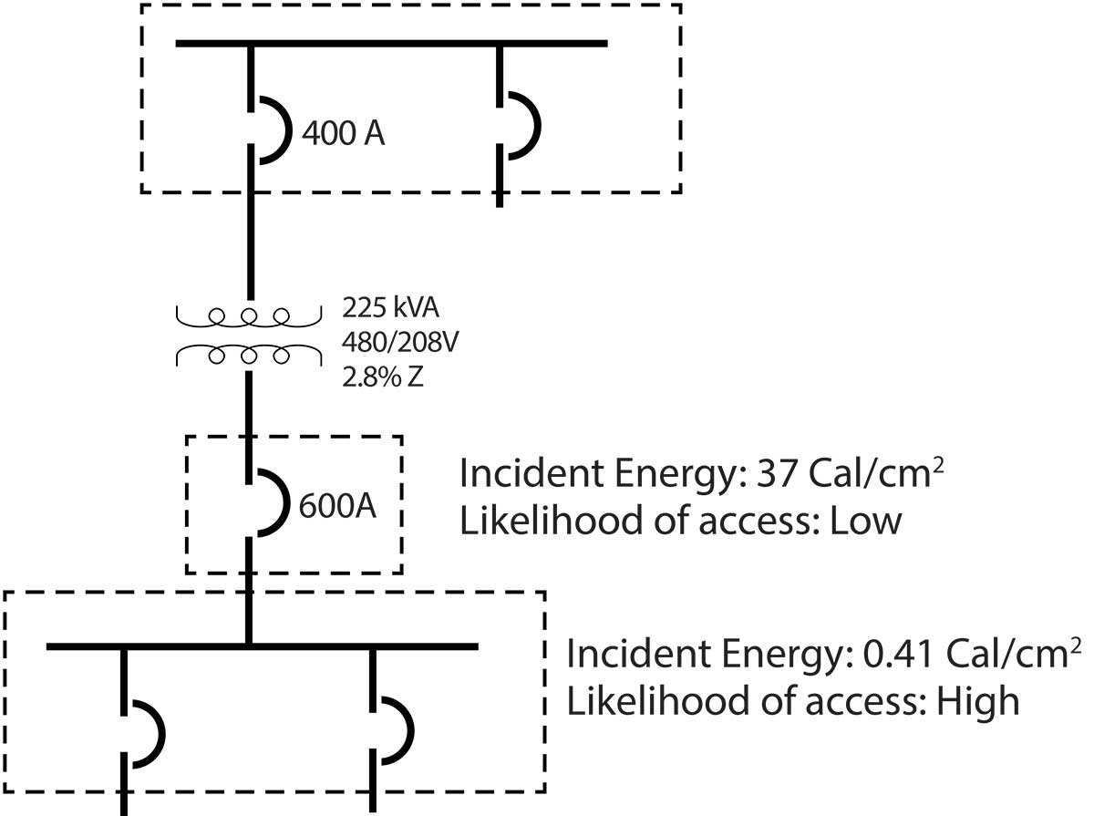
As I noted in my opening paragraph, we can learn from this discussion and leverage this knowledge in other similar areas of the power system. The presence of a transformer in between a panelboard and the next upstream overcurrent protective device, as shown in Figure 1a, presents a challenge to incident energy at the downstream panel. Based on this discussion, the incident energy at the downstream panelboard, as shown in Figure 1a, is a double-digit number placing the electrical worker in a very caustic environment.
The placement of barriers on the lineside of the main OCPD in that panel can significantly decrease the likelihood of an event, but it does not enable the reduction of the calculated incident energy. It is worth noting that a simple change to the design can significantly increase safety for the electrical worker. Figures 1a and 1b illustrate what can be achieved with a design change and presents a generic design option that can be used both at the service and at the secondary of any power distribution transformer. The premise of this change is to push the higher incident energy into an enclosure that is rarely accessed by an electrical worker providing lower incident energy and the ability to easily establish an electrically safe working condition at equipment with a high likelihood of being accessed. The focus of designs can exceed bare minimum code requirements, but together with the principles that the NEC brings to the table, and knowledge of hazards, design approaches can create a safer workplace.
References
- NFPA 70®, National Electrical Code®, 2017 edition. Copyright© 2016, National Fire Protection Association. For a full copy of NFPA 70®, please go to www.nfpa.org.