
The City of Bakersfield, California, is a city of approximately 400,000 residents, located in the Southern San Joaquin Valley, about 100 miles north of Los Angeles. We are an extremely busy jurisdiction for solar photovoltaic (PV) installations. When I first started as the chief electrical inspector for the city back in 2005, we inspected one to two PV systems per week. The weekly average has now increased to 100-150 residential PV installations. Since 2005, we have had the opportunity to permit, inspect and approve more than 40,000 systems total.
This article will examine some of the basic electrical calculations used to validate system design. The information presented will be based on the 2017 edition of the National Electrical Code (NEC). Although some of the Code references may change from cycle to cycle, the basic principles are much the same.
The Role of Inspectors
Before we begin, it’s important to consider the role of inspectors when examining PV systems. I spent most of my career as an installer (25 years). Although I am now an AHJ, I don’t see it as a major difference because, in either case, correct installation is the goal.
Correct installation is essential for any electrical system but can be more challenging when dealing with new technologies. Constantly evolving technology results in new products, installation methods and code requirements. Confusion regarding the requirements can also result.
PV Systems Basics
What is a PV system? The National Electrical Code (NEC) defines a photovoltaic (PV) system in Article 100 as “the total components and subsystems that, in combination, convert solar energy into electric energy for connection to a utilization load.”
A PV system is not just the modules up on the roof, but it’s the total components and subsystems that, in combination, convert solar energy into electric energy. If the system is not interconnected with a utility or other primary source, then the requirements of NEC Chapters 1-4 and Article 690 are applicable. If interconnected with the utility grid or other primary source , the interconnection requirements will be covered by Article 705 of the NEC. The systems discussed in this article today will be central inverter, utility-interactive, and interconnected with a primary source.
An off-grid system that is not interconnected with any other primary sources of electricity would only be subject to NEC Chapters 1-4 and Article 690. Some requirements are duplicated in NEC Articles 690 and 705 because application is dependent upon the interconnection.
What does a PV inverter do? The inverter is an electronic power converter that converts the direct current (DC) output from an array of modules into alternating current (AC). The alternating current output of the inverter can be used to supply a premises electrical system, feedback to the utility grid, or both. The AC output of a utility-interactive inverter will be synchronized with the utility grid or other primary source.
Figure 1 is a block diagram that illustrates the concept. PV source circuits are indicated by the red box on the far left. The box represents the array of modules on the roof which produce the direct current. The PV output circuits route the DC to the inverter input circuit. The inverter converts the DC to AC synchronized with utility or other primary source. The inverter AC output is used to supply the grid and/or the premises wiring system.
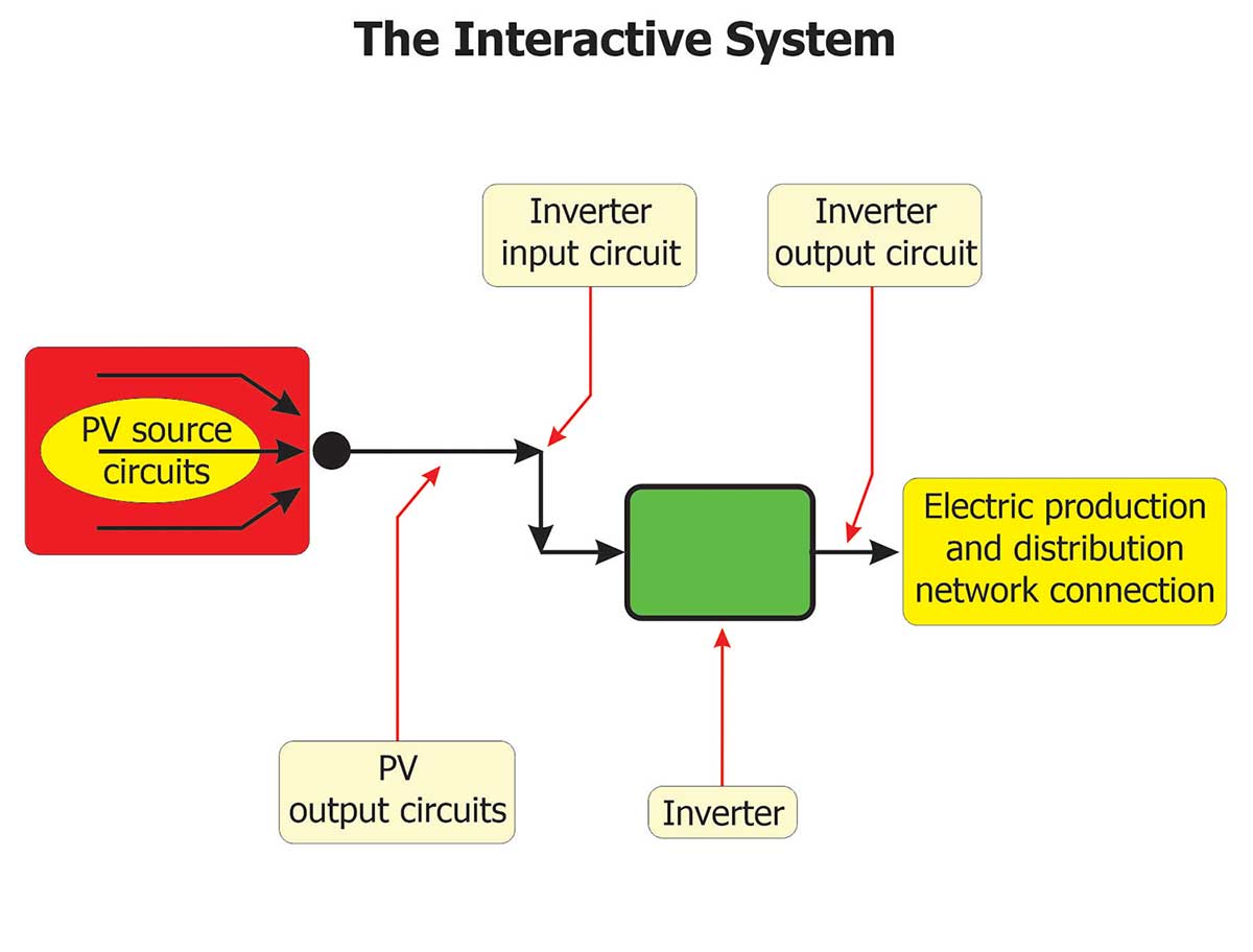
Figure 2 provides an illustration identifying the specific components. Please take note of the red line located in the middle of the inverter. We’re going to look at the system conceptually in two parts: the DC side and the AC side. I like to approach PV system design review in the middle, by starting with the inverter and the AC output.
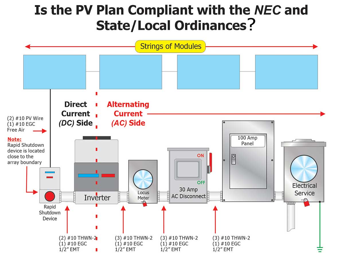
Why start with the AC side? My experience has been that most plan review comments result from design problems on the AC half of the system. That doesn’t mean there aren’t important design considerations for the DC portion, but we’ll leave those for another article.
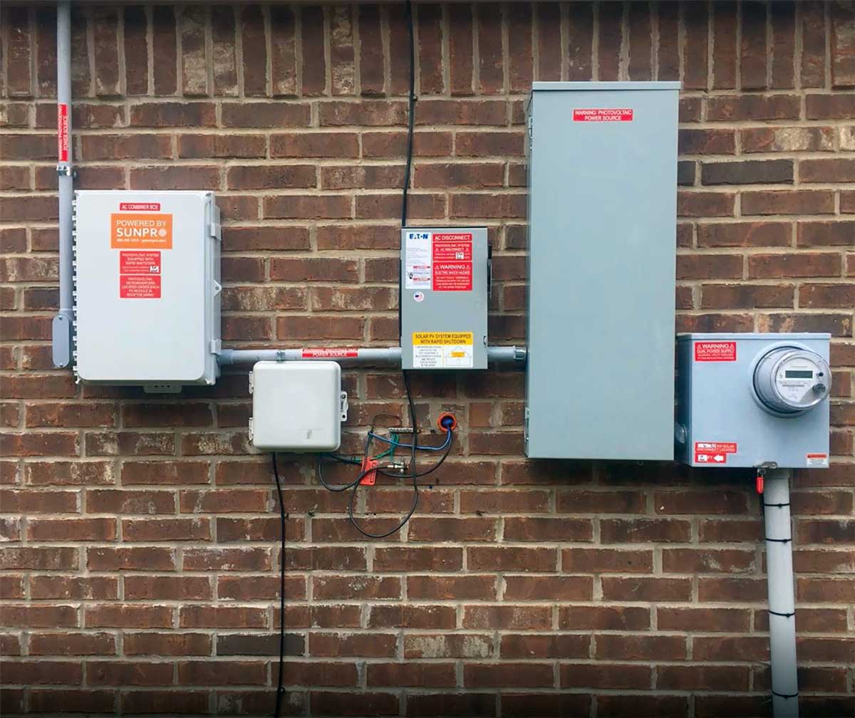
Photo 1 is a picture of an actual system like the block diagram in Figure 2.
The basic elements of a PV system array are illustrated by Figure 3. The individual photovoltaic cells are combined in a manufactured unit known as a module. The modules are connected in series strings and often connected with other strings in a series-parallel arrangement. The output of the combined PV source circuits is known as the PV output circuit.
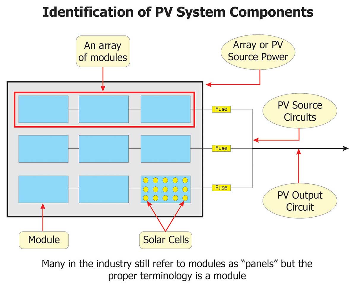
The Figure 3 illustration indicates three source circuit fuses. Be aware that fuses are not always required. Based on the rules and exception of NEC 690.9, fuses are generally not necessary for smaller residential systems.
Photo 2 is a picture of an array I took during an inspection at an apartment complex. It’s difficult to see the string conductors because the modules are close to the roof, but the DC output circuit conductors are located in the conduit on the lower right side of the picture.

There are three basic design elements of the AC side that require simple math to validate: the inverter output overcurrent protective device (OCPD) rating, the output conductor ampacity, and the permitted PV contribution to the premises wiring system. These are also the elements that generate most plan review comments for me.
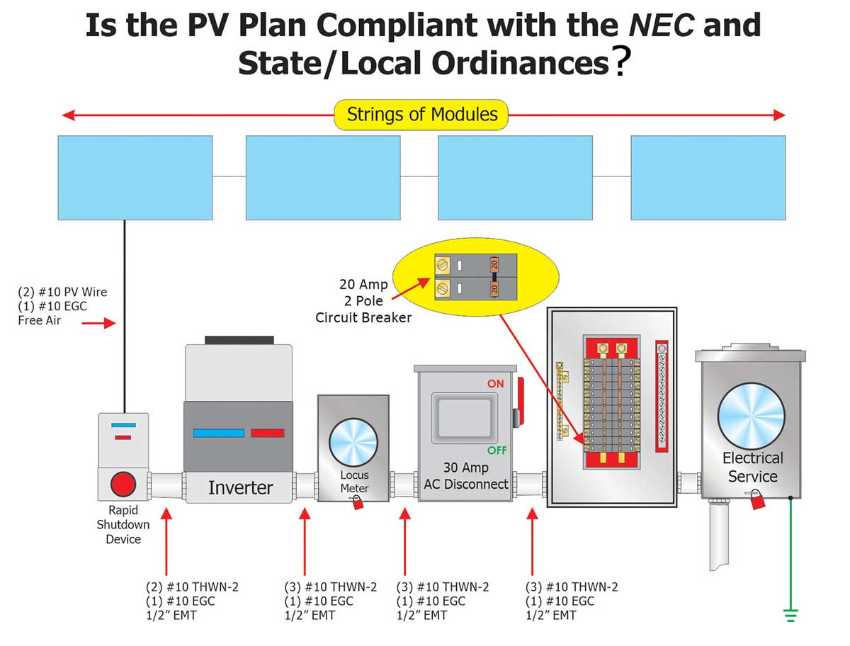
Please refer to Figure 4. Three questions need to be answered:
- What is the minimum required inverter overcurrent device rating?
- What’s the required inverter AC output conductor ampacity?
- What’s the permitted PV system contribution to the panelboard?
The inverter size (the KW rating) in Figure 4 is not identified, but a 20-ampere circuit breaker is indicated for the inverter. Is this correct?
Inverter Output OCPD Rating
Overcurrent protection is required for the protection of conductors and equipment. Current must be limited in accordance with the ampacity rating of equipment and conductors to prevent overheating and/or failure. An overcurrent protective device (OCPD) is used to limit current flow to a safe level.
All PV system currents (DC or AC) are continuous. Why? Because the sun generally will be shining for more than three hours a day. If it didn’t, you probably wouldn’t be installing a PV system! Anytime maximum current is expected to continue for three hours or more, it’s a continuous current, and there are requirements that must be considered.
The minimum rating for the PV inverter AC overcurrent device is 125% of the rated inverter continuous output current unless the overcurrent device is listed for continuous operation at 100% (see NEC 705.60). The circuit breaker in our sample system is not listed for continuous operation therefore we must apply the 125% factor.
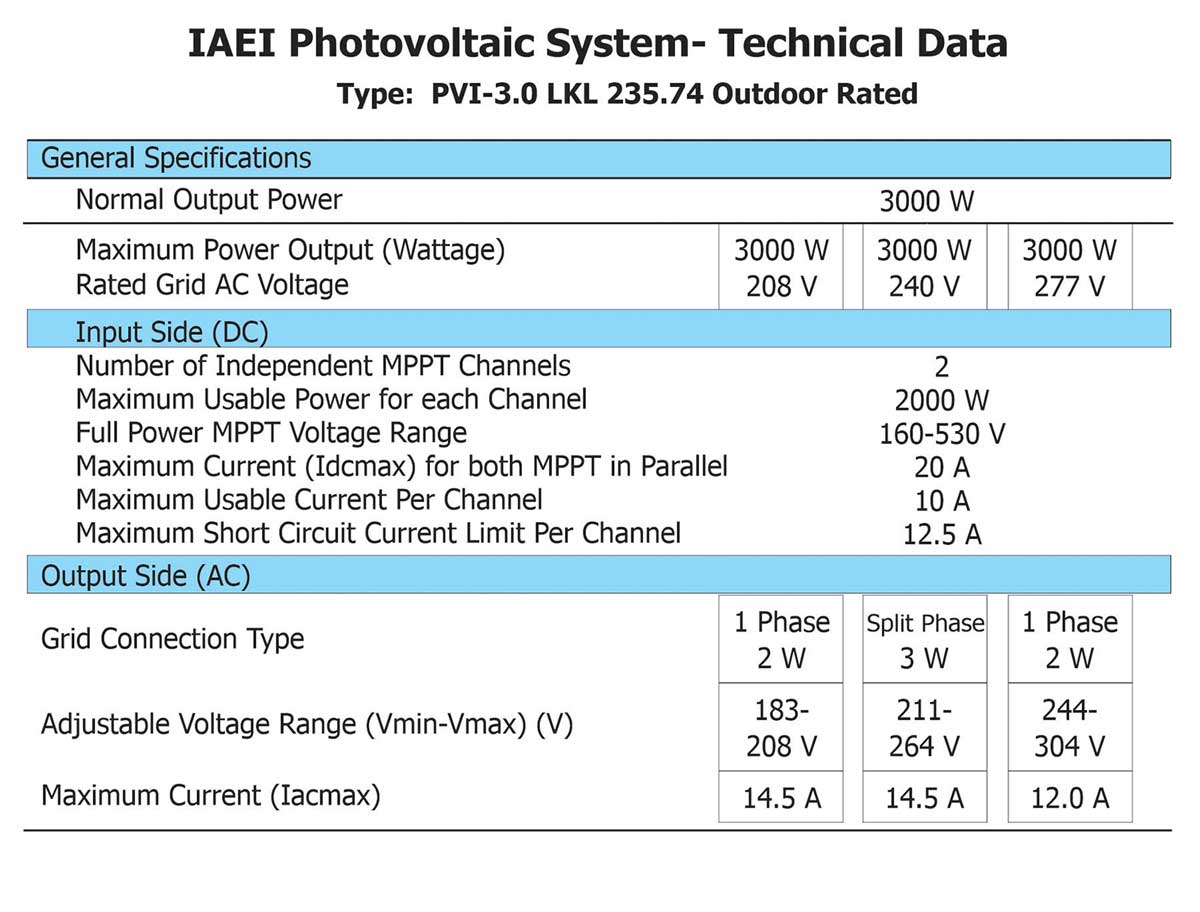
Figure 5 provides an example of a typical inverter datasheet. A key element of the datasheet is the inverter rating (kW). The normal output power is indicated as 3000 watts (3 kW) and the inverter can be interconnected to a 208, 240, or 277-volt premises distribution system. The output current may differ based on the system voltage, so be sure to reference the correct column.
The bottom row provides the maximum current output of the inverter. This system is interconnected at 240-volts. See the center column. Notice that if this were a 208-volt system, the maximum current rating would still be 14.5 amperes. But for a 277-volt interconnection the output would drop to 12.0 amperes. Our system is for a residential dwelling unit with a 240-volt supply, and therefore, a 14.5 ampere current output.
Per the Code reference, the minimum rating for the PV inverter (AC) overcurrent device is 125% of the rated inverter continuous output.
The datasheet in Figure 5 states that the maximum output current is 14.5 amperes at 240-volts.
Minimum OCPD is 14.5 A x 1.25 = 18.125 A
I am not aware of an 18-ampere circuit breaker. The Code permits use of the next larger (800 ampere or less per NEC 240.4) standard overcurrent device rating; 20 amperes in this example. That’s the minimum rating. The OCPD rating can’t be rated less than 20 amperes. Is it possible to use an OCPD with a higher current rating?
If the inverter were tested with larger overcurrent protective device rating during the certification process, then a larger OCPD may be allowed. In that case, the installation instructions should provide the information. I recommend that plan reviewers or inspectors consider the minimum required OCPD rating as the maximum unless someone can show you differently. If the designer can provide documentation that a larger ODPD rating is permitted by the manufacturer in accordance with the listing, then approval is possible.
In our jurisdiction, the field inspector cannot approve an installation where the installed inverter circuit breaker rating does not match what is required by the approved plan. The correct inverter OCPD rating is validated at the plan review stage.
Standard Ampacity Ratings
Standard overcurrent device (fuses and inverse time circuit breakers) ratings are provided by NEC Table 240.6(A).
It may be desirable for you to create a chart like that in Table 1 for the common inverter ratings. If you perform a lot of PV system plan reviews, you will soon memorize the OCPD ratings based on common inverter kW sizes.
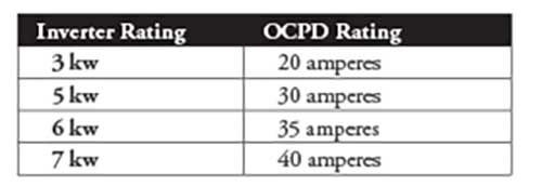
Table 1 does not contain every possible inverter rating. Always confirm the rated output through the manufacturer’s datasheet.
What if there are multiple inverters?
A common question involves systems with multiple central inverters. How do we do the math? Do we just add up the minimum OCPD ratings for each inverter, and use the sum for the single interconnection circuit breaker?
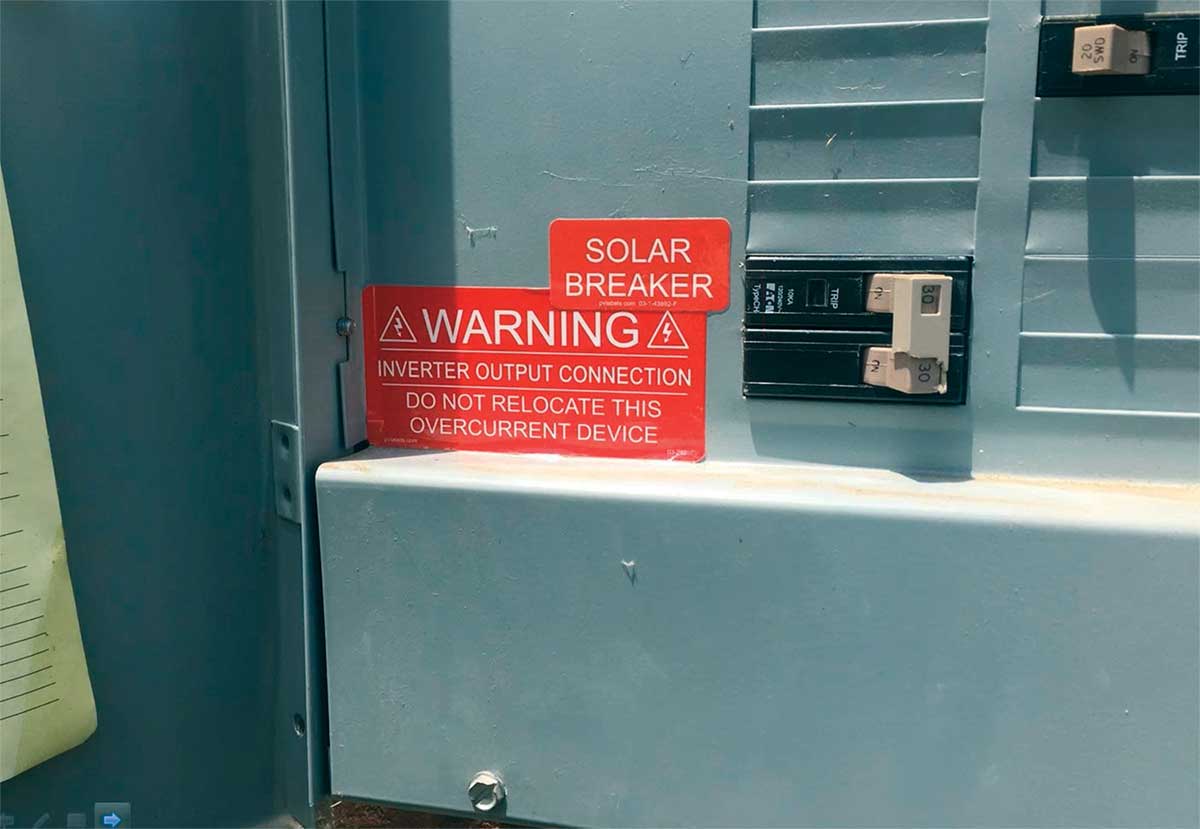
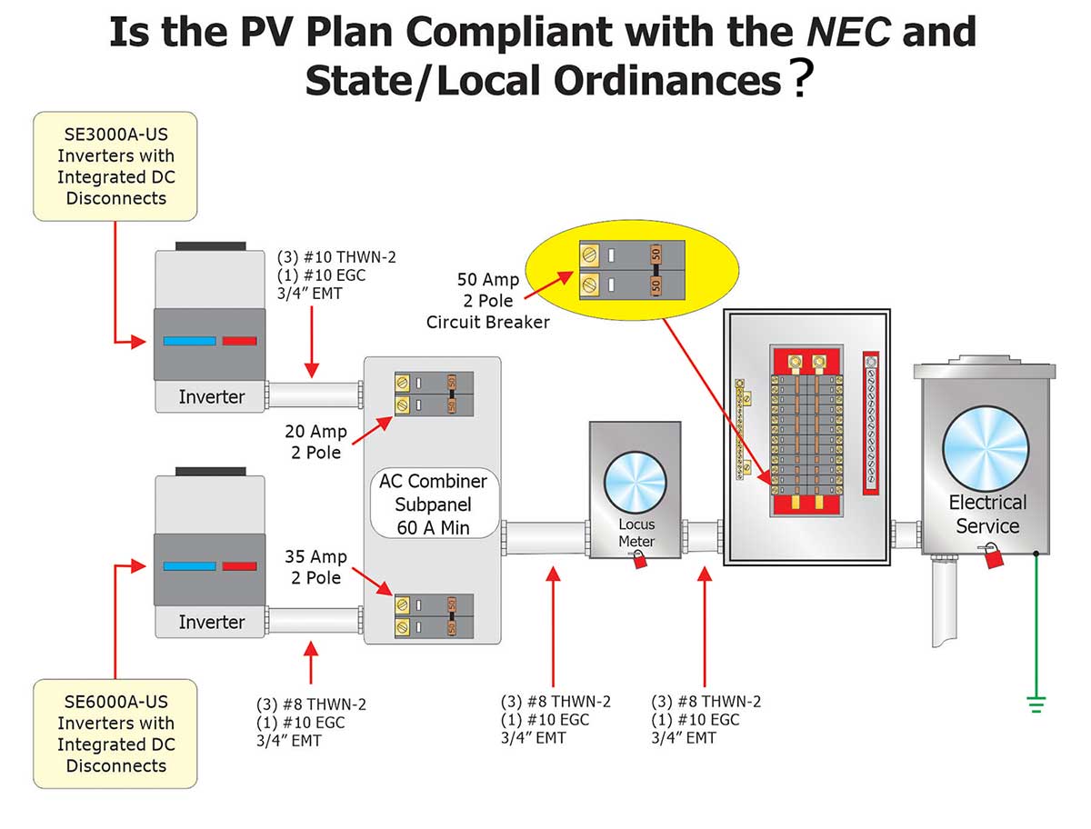
Figure 6 provides an example of a system with multiple central inverters. There are two inverters on the left — 3 KW on the top and a 6 KW on the bottom. Each of those is required to be protected individually by an overcurrent protective device. The requirements differ for microinverter and AC module systems.
In this example, the two inverter outputs are combined in a panelboard. A panelboard used in this manner might be described as an “AC combiner panel”. A standard panelboard or a specially designed unit could be utilized. But in either case, individual OCPD is required for each central inverter. A 20-ampere circuit breaker for the 3 KW inverter and a 35-ampere circuit breaker for the 6 KW inverter is indicated.
What would be the minimum required rating for the panelboard feeder circuit breaker? Is it the sum of the 20 ampere and 35 ampere individual inverter circuit breaker ratings (55 amperes)? Is a 55 -ampere circuit breaker available? So, would a 60-ampere circuit breaker be required? Is that the minimum required rating? The answer is no. Let’s look at the correct method.
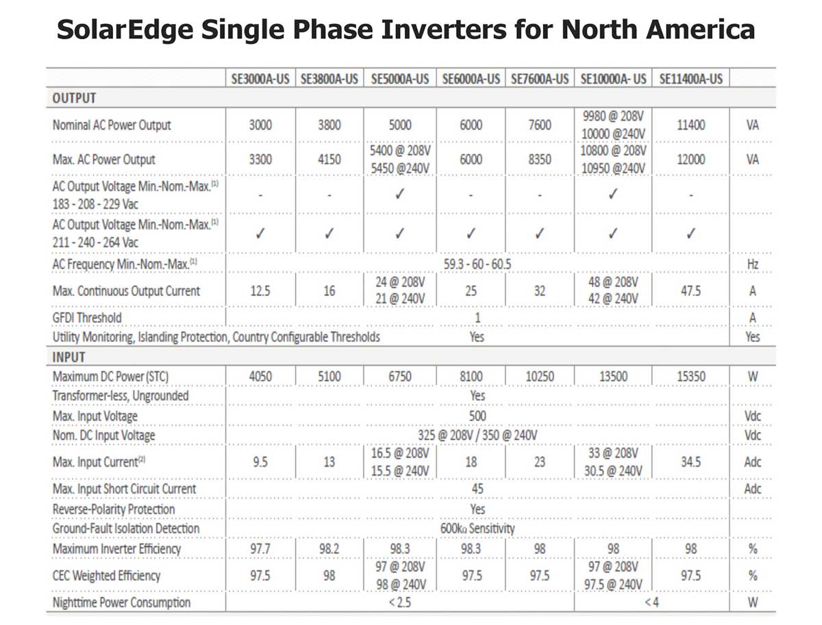
Figure 7 provides an inverter manufacturer datasheet. The 3-kW inverter provides a maximum continuous output current of 12.5 amperes, and the 6 KW has an output of 25 amperes.
For the 3 KW inverter the continuous output current is 12.5 amperes.
12.5 amperes x 1.25 = 15.6 A
Therefore a 20-ampere circuit breaker is required.
For the 6 KW inverter the continuous output current is 25 amperes.
25 A x 1.25 = 31 A
Therefore a 35-ampere circuit breaker is required.
We have established the minimum circuit breaker ratings for each inverter. But how is the circuit breaker rating for the feeder that supplies the panelboard determined? In the same manner as the individual circuits.
Sum of both inverter outputs: 25 + 12.5 = 37.5 A
Minimum required circuit breaker rating: 37.5 A x 1.25 = 46.9 A
Therefore, the minimum circuit breaker rating is 50 amperes
Simply adding the two individual circuit breaker ratings (20 + 35) results in a 55-ampere rating. But you come up with a different answer when the correct method is used. That’s critical because you wouldn’t want to turn down a plan if you think they need a 60-ampere circuit breaker based on adding 20 + 35. The actual minimum required rating is 50 amperes in this example.
The minimum feeder OCPD rating could be greater than 50 amperes if desired, or if necessary for another reason (such as supplying loads).
The method is the same regardless of the quantity of inverters. The numbers may be larger but the same process is used.
Inverter Output Conductor Ampacity
Next are calculations for the inverter output conductor ampacity. After establishment of the minimum overcurrent device rating, the corresponding conductor ampacity must be validated. The order of validation is important because the conductor ampacity will be directly related to the overcurrent protective device rating. The minimum required ampacity for the conductors is established by NEC 705.60 and 690.8. The minimum ampacity for the inverter output conductor must be larger of 1) or 2) below:
- 125% of the inverter continuous output (unless the overcurrent device is listed for continuous operation at 100% of its rating).
- 100% of the inverter continuous output after application of adjustment and correction factors.
For simplicity, in our example here, we will assume that the OCPD is not rated for continuous operation and that 1) above will provide the larger result. For this calculation we will also reference the datasheet of Figure 5. The inverter continuous output rating was used to establish the minimum (and perhaps maximum) overcurrent protective device rating of 20 amperes. The designer specified #10 THWN-2 copper conductors. Will the conductors have the sufficient ampacity?
It may seem redundant, but the process for determining conductor ampacity begins the same way as for minimum overcurrent protection. The inverter datasheet of Figure 5 identifies the continuous current output as 14.5 amperes at 240 volts for the 3 kW unit.
Output Current = 14.5 amperes
Minimum Conductor Ampacity/OCPD
Rating = 14.5 A x 1.25 = 18.125 A
The conductor and OCPD must have an ampacity of at least 18 amperes. Because a 20 ampere OCPD is necessary (18 ampere is not a standard OCPD rating), the conductor will also require an ampacity of 20 amperes.
What is the ampacity of the conductor? See NEC Table 310.15(B)(16). The ampacity will be based on the conductor insulation temperature rating of 60°C, 75°C, or 90°C.
Be sure to consider the asterisks (*) of Table 310.15(B)(16) for conductor AWG sizes 18, 16, 14, 12, and 10. The asterisks refer the user to 240.4(D) for conductor overcurrent protection limitations. Regardless of the temperature rating of the conductor, and any conditions of use, there are OCPD limitations for small conductors.
Figure 4 identifies the inverter output conductor type and size as #10 THWN-2. Table 310.15(B)(16), for Types THWN-2 provides an ampacity rating of 40 amperes before application of any conditions of use.
There are maximum OCPD limitations for small conductors (except in special conditions). Three common conductor sizes and associated limitations include:
- #14 AWG conductor (copper) can never be protected greater than 15 amperes
- #12 AWG conductor (copper) can never be protected greater than 20 amperes
- #10 AWG conductor (copper) can never be protected greater than 30 amperes
The most common design violation I have encountered with residential PV systems is use of a #10 conductor for a 35 or 40-ampere inverter output circuit. Table 1 indicates that a minimum 35-ampere device is required for a 6 kW inverter and a 40-ampere device is necessary for a 7 kW system. These are very common residential PV system and/or inverter ratings.
Unfortunately, what’s also very common is that designers will specify a #10 conductor for the 6- and 7-KW inverter output circuit. The #10 conductor size cannot be approved based on the rules of 240.4(D) even if otherwise permitted by the ampacity tables and conditions of use.
PV System Contribution
The allowable PV system contribution is based on the ampacity rating of the panelboard bus and overcurrent protective device. Are there limitations? The answer is yes, there are limitations, but also several options for compliance.
Busbars are conductors, and all conductors must be protected at their ampacity. The panelboard bus rating determines the main circuit breaker or feeder circuit breaker rating. Can a 100-ampere panelboard bus be protected by a 200-ampere main breaker circuit breaker? The answer is no; you must protect all conductors, including the bus, at rated ampacity.
Where a panelboard is supplied by a utility or other primary source, the PV system will be an additional source of electricity. A PV system is a supply of electricity for the panelboard.
Source currents are only limited by the source overcurrent device. Some might say “well, yeah, but if the PV system is supplying current, then that means the utility is not, so why does it matter?” It matters because the available current, from all sources, cannot exceed the rating of the busbars except as permitted by NEC 705.12.
The sum of branch circuit breaker ratings may exceed the panelboard busbar ampacity. The bus is protected at rated ampacity by either the feeder or the main circuit breaker.
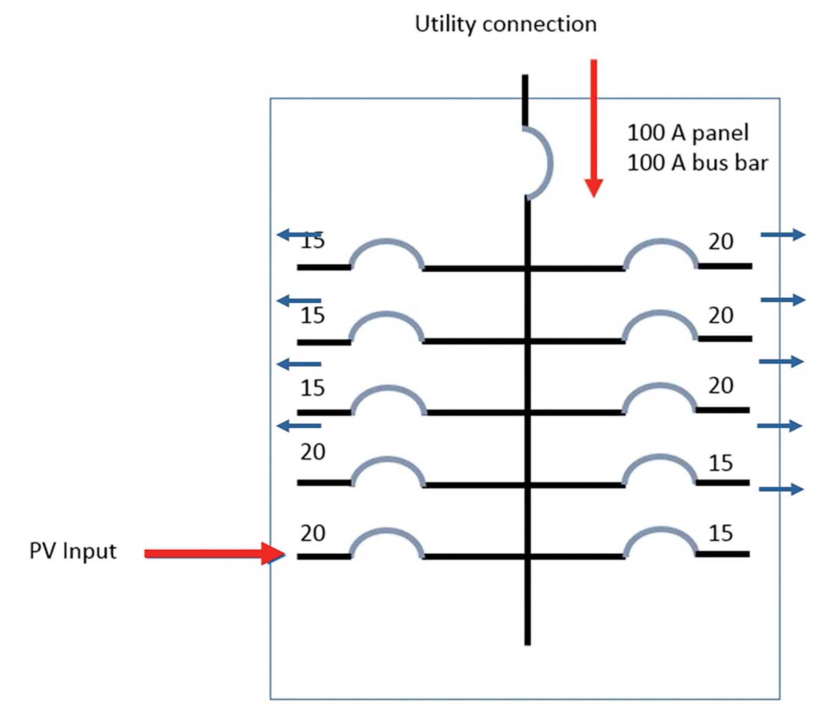
Figure 8 provides an illustration of the concept. The PV system inverter is a supply to the panelboard along with the utility. The utility supply is limited by the 100-ampere main circuit breaker at the top and the PV system supply is limited by the 20-ampere circuit breaker at the bottom. Both the PV input and the utility connection are supplies. What limits ampacity on this 100-ampere rated bus bar? The utility and PV system overcurrent devices provide the necessary limitation.
The rules for load-side source interconnections are found in NEC 705.12. The basic concept is that the panelboard must be equipped with bus sufficient for the PV contribution.
There are specific limitations where panelboards are supplied simultaneously by a primary source of electricity and one or more other load side power sources and are also capable of supplying multiple branch circuits and/or feeders. We will consider two options. The “120% rule” of 705.12(B(2)(3)(b) and the “limited load rule” of 705.12(B)(2)(3)(c).
120% rule
NEC 705.12(B)(2)(3)(b) states that the sum of the main circuit breaker rating (or the feeder breaker) and 125% of the inverter output are not to exceed 120% of the panelboard bus rating. There are requirements that must be met to use this allowance. First, the PV system circuit breaker must be located at the opposite end of the panelboard bus from the primary supply connection. With all of the load connections located between the two supplies there cannot be an oversupply at any one location on the bus bars. A warning label is also required to prohibit relocation of the PV system circuit breaker.
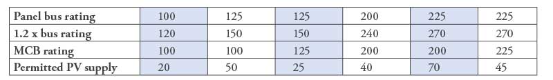
Common panelboard and main circuit breaker ratings are indicated in Table 2. The top row (row 1) contains common panelboard bus ratings. Under the 120% rule, a contribution from all sources up to 120% of the busbar rating is permitted. That equates to 120 amperes for a 100-ampere panel bus (row 2) from all sources. The next variable is the main circuit breaker or feeder circuit breaker rating (row 3). A 100 ampere-panelboard equipped with a 100-ampere main circuit breaker is permitted up to 20 amperes of PV supply. A 125 ampere-panelboard equipped with a 100-ampere main is allowed up to 50 amperes of PV system contribution.
But a 125-ampere panelboard equipped with a 125-ampere main is only permitted up to 25 amperes from the PV system. There’s an interaction between the main circuit breaker rating and panel bus that determines the permitted PV supply under this rule.
Remember that 125% of the inverter output is used for these calculations, not the inverter circuit breaker rating.
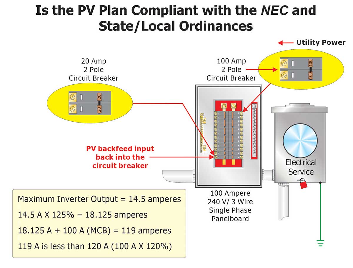

Figure 9 puts the math into action. The 100-ampere panelboard equipped with a 100-ampere main circuit breaker is allowed 120 amperes from all sources (100 amperes x 120%). What does the Figure 4 system indicate? There is an 18.125-ampere continuous output current from the inverter to the panelboard. Since 118 amperes is less than the 120 amperes (100 A x 120%) permitted maximum, the design is code compliant.
Maximum Inverter Output = 14.5 amperes
14.5 A x 1.25 = 18.125 A
18 A + 100 A = 118 A
118 A is less than 120 A (100 A x 1.2)
What about the two inverter system of Figure 6? The PV system contribution is 45.7 amperes from both inverters. Is that compliant?
The 225-ampere panelboard is protected by a 200-ampere main circuit breaker. Using the 120% rule, 270 amperes from all sources is permitted.
Maximum Inverter Outputs = 12.5 amperes and 25 amperes
(12.5 A + 25 A) x 1.2 = 46.875 A
47 A + 200 A = 247 A
247 A is less than 270 A (225 A x 1.2)
The PV system contributes 47 amperes. A supply of up to 70 amperes is permitted. Therefore, the system is compliant.
705.12(B)(2)(C)(3)(c)
The limited load approach can be useful where a panelboard contains limited quantities of branch circuit breakers. A design is compliant where the sum of the ampere ratings of the PV supply and the branch/feeder overcurrent devices does not exceed the panelboard busbar rating. It is not necessary to consider the utility supply (main or feeder circuit breaker). Add the ratings of the PV circuit breaker(s) and all the load circuit breakers; if the sum does not exceed the panelboard bus rating, then the design is compliant.
When using this method, a warning label is required so that the design limitation will not be violated in the future.
Is the panelboard in Figure 9 compliant with the limited-load allowance? Typically, with this many branch circuit load breakers in a panelboard, probably not. The limited load concept is very useful where a panelboard is used only for combining multiple PV system inverter outputs or where there are only a few branch circuit loads.
Where a panelboard is used only to combine the output of multiple inverters, the sum of all inverter circuit breaker ratings is permitted to equal the panelboard bus rating.
Options for Compliance
Are there other options?
A new panelboard with a larger bus rating or a smaller main breaker rating (if load permits) could be installed. A reduction in the main circuit breaker rating is very common in this jurisdiction. But we verify that the reduced rating is still large enough for the connected load. Other options would include a smaller PV system or interconnection through a feeder or supply-side tap.
It is critical to recognize a supply-side interconnection (supply-side of the main disconnect) during a plan review. If the panelboard manufacturer did not provide for a supply-side connection, then a field evaluation by a qualified body to the applicable US product safety standard may be necessary for any field modifications.
Don’t Forget the Basics
There are basic conductor ampacity requirements that must be considered for all electrical installations. These include:
- The conductor ampacity based on temperature rating cannot exceed the lowest temperature rating of any connected device or conductor. See NEC 110.14(C).
- Temperature correction and adjustment factors for ambient temperature and rooftop locations. See NEC 310.15(B).
- Adjustment factors for more than 3 current-carrying conductors in a raceway or cable. See NEC 310.15(C).
I hope this has been helpful. We’ve covered some of the basic formulas and issues to look for when either installing or inspecting PV systems.
Editor’s Note: This article is an edited transcript extracted from Photovoltaic Systems — Electrical Calculations with Pete Jackson, a live training presentation recorded and available on iaeicourses.org.