Applying the rules of the 2002NECfor tap conductors is a topic that has generated many interesting code discussions on jobsites as well as at inspector meetings. The discussion and application of the tap rules in the NEC must begin with the conductor in question.

Figure 1
What Makes a Conductor a Tap Conductor?
We must first determine theNECterm for the conductor. The terms home run and sub-feeder are not terms used in the Code, and are a good example of how we can start off on the wrong foot when using the NEC. We work primarily in the electrical industry with three types of conductors: branch-circuit, feeder and service conductors. As summarized from the definitions of service and service conductors in the NEC, service conductors must originate from an electrical utility source and end at the disconnecting means. Note that the disconnecting means must contain or be immediately adjacent to the service overcurrent protective devices as required by 230.90 and 230.91. The Code definition of branch circuit is: “The circuit conductors between the final over-current device protecting the circuit and the outlet(s).” Feeders are essentially everything between the service equipment and the final overcurrent device. TheNECdefinition of feeder is “All circuit conductors between the service equipment, the source of a separately derived system, or other power supply source and the final branch-circuit overcurrent device.” Care must be taken when applying this definition of feeder to transformer secondary conductors. Conductors from a separately derived system such as a transformer are not always feeders; in fact, in most cases these conductors are tap conductors. As stated in 240.4(F) and 240.21(C)(1), “Single-phase (other than 2-wire) and multiphase (other than delta-delta, 3-wire) transformer secondary conductors are not considered to be protected by the primary overcurrent protective device.” Transformer secondary conductors that are not considered protected by the primary overcurrent device do not have overcurrent protection at the point of supply and are tap conductors.
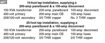
Table 1. Difference between the 25-tap rule in 240.21(C)(6) and existing 10-foot tap rule in 240.21(C)(2)
Examples of transformer secondary conductors, which are always tap conductors, are those from single-phase 3-wire, three-phase 4-wire delta and wye-connected secondarys. In order for us to apply the name tap conductor we must first be certain that we are not dealing with service, feeder or branch-circuit conductors.
Tap conductors are defined in 240.2 of the 2002 NEC as: Tap Conductors “As used in this article, a tap conductor is defined as a conductor, other than a service conductor, that has overcurrent protection ahead of its point of supply that exceeds the value permitted for similar conductors that are protected as described elsewhere in 240.4.” Basically a conductor is considered a tap conductor where it has overcurrent protection higher than its rated ampacity. New in the 2002 NEC, a comma was added after “”service conductor”” to clearly point out that service conductors are not considered to be tap conductors. Where the NEC permits taps from a service conductor, as in 230.82(4) for example, those conductors are merely extensions of service conductors, not tap conductors. Service conductors are treated as being unprotected conductors, as seen in the many restrictive requirements in Article 230. The provisions of 240.21 will not apply to service conductors.

Figure 2. Tap rules for primary and secondary conductors
Note that the definition of tap conductor exists in Article 240, thereby limiting the use of this definition to Article 240. While this definition is limited to a single article, in the NEC it is the platform for most uses of the term tap to a current-carrying conductor. In general motor-circuit conductors are not tap conductors. While the branch-circuit, short-circuit ground-fault protective device may be set at a value above the conductor ampacity, it provides only short-circuit and ground-fault protection. The overloads protect the motor circuit against overloads at their rated ampacity and overcurrent protection is then provided in the form of two separate devices.
Taps from branch circuits are addressed in 210.19. These taps must be sized with a sufficient ampacity for the load served and are further limited as to how small a conductor may be installed and the maximum length of the conductors.
New 25-Foot Transformer Secondary Tap Rule
Applying the tap rules for transformer secondary conductors can put even the experienced installer into a tailspin. The NEC is calling this a secondary conductor and there is not a definition in Article 100 for a secondary conductor. Here again it is the terms used in the NEC that can be the source of confusion. Branch-circuit conductors are branch-circuit conductors. Feeder conductors are feeder conductors. Transformer secondary conductors are transformer secondary conductors. However, transformer secondary conductors must be identified by the installer and inspector as they will be classified as branch-circuit, feeder, or tap conductors. The first step in applying the rules of the NEC to any conductor is to properly identify the type of conductor in question. This remainder of this article will address the use of transformer secondary conductors, which are tap conductors.
Feeder taps and transformer secondary taps must meet the requirements of 240.21. The general rule for the location of overcurrent protective devices protecting ungrounded conductors in 240.4 is that they “..be located at the point where the conductors receive their supply except as specified in 240.21(A) through (G)…”
The most common tap applications are the 10-foot and 25-foot. Feeder taps in 240.21(B) made it through the 2002 code cycle with changes only affecting tap conductors located outdoors. New in the 2002 NEC for transformer secondary conductors is 240.21(C)(6), which will now clearly permit a 25-foot transformer secondary conductor taps in a commercial installation. As the submitter of this proposal pointed out in his substantiation, the only 25-foot tap rule for transformer secondary conductors in the 1999 NEC existed in 240-21(c)(3) for “industrial installations only.” In order to allow a 25-foot tap in the 1999 NEC, both the AHJ and installer had to liberally interpret the provisions of 240-21(b)(3). The new 25-foot tap rule for transformer-secondary conductors is implemented in the 2002 NEC as follows:
The term industrial installation has been added to the title of 240.21(C)(3) to limit its application to only that occupancy. The new text in 240.21(C)(6) is compiled from three rules in 240.21(B)(3) and reads as follows:
240.21(C)(6) Secondary Conductors Not Over 7.5 m (25 ft) Long.Where the length of secondary conductors does not exceed 7.5 m (25 ft) and complies with all of the following:
1. The secondary conductors shall have an ampacity that, when multiplied by the ratio of the secondary-to-primary voltage, is at least one-third of the rating of the overcurrent device protecting the primary of the transformer.
2. The secondary conductors terminate in a single circuit breaker or set of fuses that limit the load current to not more than the conductor ampacity that is permitted by 310.15.
3. The secondary conductors are suitably protected from physical damage.1
The following is an example of the application of this new rule.
The installation is a 150-KVA transformer with a 480-volt primary and 208/120-volt secondary. The transformer secondary conductors are 22 feet long.
The first step is to determine the value of the primary and secondary amps. The current values are equal to the (KVA x 1000) divided by the (line voltage x 1.73). The result for this installation is 180 amps primary current and 416 amps secondary current. Next, the primary overcurrent protective device is sized per 450.3(B), 180 amps at 125 percent equals an overcurrent device size of 225 amps. The ratio of the secondary to primary voltage is 208/480, .43 or 43 percent. The OCPD is sized at 225 amps, 1/3 of 225 amps is 75 amps.

Figure 3. Multiple taps from a single transformer secondary must originate from the transformer.
Compliance with 240.21(C)(6)(1) requires that the conductor ampacity when multiplied by the ratio of secondary to primary voltage is at least 1/3 the ampacity of the primary overcurrent device. If a conductor size is given or already installed, we can determine if the installation is compliant by multiplying the ampacity of the conductor times the ratio of the secondary-to-primary voltage. For example, a THW 500-kcmil copper has a table (310.16) ampacity of 380 amps. To determine if this is compliant we multiply 380 amps x .43 = 163 amps. This is above 1/3 of the size of the primary OCPD of 75 amps and is permitted. Note that 240.21(C)(6)(2) requires that the secondary conductors terminate in a single circuit breaker or set of fuses that limit the load current to not more than the conductor ampacity that is permitted by 310.15. We can determine the minimum size THW, copper conductor permitted in a 25-foot tap from this transformer by dividing 1/3 of the size of the primary OCPD by the ratio of the secondary-to-primary voltage. 75 amps divided by .43 = 174 amps. The minimum size THW copper permitted for a 25-foot tap from this transformer secondary would be a 2/0 with a table (310.16) ampacity of 175 amps.
The key to understanding the difference between the 25-foot tap rule for transformer secondary conductors in 240.21(C)(6) and the existing 10-foot tap rule in 240.21(C)(2) is that the 25-foot rule places a limitation on how small a conductor may be installed. In the above example we could not use a THW copper conductor smaller than a 2/0. Using the above example in a 10-foot and 25-foot installation the difference is illustrated in Table 1.
The 10-foot tap permits a No. 3 THW copper to serve the fused 100-amp disconnect while the 25-foot tap requires a minimum size of 2/0 THW conductor.
Note that in this installation consisting of two sets of secondary conductors from a single transformer, both sets of conductors must originate at the transformer secondary. For example we could not use a single secondary conductor sized at 500-kcmil THW copper into a wireway and then tap to supply the panelboard and disconnect. It is not permitted to “tap a tap.” This is specifically prohibited in this installation by the last sentence of 240.21 as well as in 240.21(C)(2)(2) and 240.21(C)(6)(2).
Outdoor Taps

Figure 4. Secondary conductors must be at least one-third of the rating of the primary overcurrent device
CMP-10 submitted a panel proposal to address confusion in the application of theNECfor outside tap conductors. This proposal was initiated by an inspector member on CMP-10 and resulted in new user-friendly text to allow feeder or transformer secondary taps to enter a building or structure under the provisions of 230.6. New language in the 2002NEChas been added to clearly point out to the user the requirements of a conductor to be considered an outside tap. This change occurred in 240.21(B)(5), 240.21(C)(4) and 240.92(C). The new text now clearly requires that the outside tap originate outside of the building. The text reads as follows: “… where the conductors are located/installed outdoors of a building or structure, except at the point of load termination.” By adding the words “..except at the point of load termination,” the intent of this requirement is clear, the tap must originate outdoors. In addition the provisions of 230.6 were extended to outside taps as follows in 240.21(B)(5)4: “The disconnecting means for the conductors is installed at a readily accessible location complying with one of the following: a. Outside of a building or structure; b. Inside, nearest the point of entrance of the conductors; c. Where installed in accordance with 230.6, nearest the point of entrance of the conductors.”
In the 1999 NEC the disconnecting means for outdoor taps entering a building or structure had to be located “…nearest the point of entrance of the conductors.” The rules in 230.6 did not apply, as the conductors were not service conductors.
These changes are good code because they are practical, easy to read and enforceable.
1NFPA 70,National Electrical Code2002, 240.21(C)(6), (Quincy, MA, National Fire Protection Association, 2002), p. 70–90 & 70-91.