Many businesses are concerned these days with the cost of electrical energy supplying power to their facility, but an increasing number of them are getting real concerned about the quality of the power being utilized at their facility. So what is the problem with the quality of power being delivered to a facility? Many businesses are extremely nervous about loss of data or data errors that can result from this “dirty power” or “electrical noise” on the system. Does this sound familiar? So what do they do? Many have extensive evaluations performed and end up with large surge protectors or filtering systems consisting of metal oxide varistors (MOVs) and capacitors to try and filter or stabilize their electrical supply system. Is that the answer? In some cases these types of devices can be effective in cleaning up some power quality issues.
In large, or even smaller, facilities, if the owner or operator is considering an attempt to clean up the power being delivered to the facility, he should start with an extensive analysis of the serving utility’s power as delivered, the electrical service, the power distribution system, the panelboards, and finally the branch circuits and what is connected to the branch circuits. One of the most important aspects of this analysis is the inspection of the grounding electrode system, the equipment grounding conductors, the bonding system, and the grounded conductor of the system. If an electrical system is not grounded properly, the voltage could be flowing unstably to begin with before it’s filtered. Section 250-2(a) of the 1999 National Electrical Code® specifically states the reasons for grounding electrical systems. The electrical system shall be “connected to the earth in a manner that will limit the voltage imposed by lightning, line surges, or unintentional contact with higher voltage lines, and that will stabilize the voltage to earth during normal operation.”
The term “quality of power” is often described in different ways and by different elements of the electrical industry. Stabilized voltages and stable waveforms are two elements which are desirable in power systems when talking about the subject of “power quality.” Grounding affects voltage stability but, more importantly, is a critical element to personal safety. Harmonic currents are a mathematical model one often uses to analyze distorted waveforms flowing at higher frequencies than the common fundamental root frequency of 60 hertz.
The term “power harmonics” is probably familiar to most individuals involved in the electrical industry, but is probably more often misunderstood. Many technical articles and publications have been written about this subject, but these articles do not always address one’s basic problems and concerns in an understandable way. This article addresses the following questions.
- What are power system harmonics?
- What effect do they have on the power distribution system in a building?
- What are common symptoms or signs of harmonics or harmonic problems?
- How does one address these issues?
Harmonics is a mathematical model of the real world. Harmonics is simply a technique to analyze the current drawn by computers, electronic ballasts, variable frequency drives and other equipment which have modern “transformer-less” or electronic power supplies. These power supplies operate according to Ohm’s Law, which states that when a voltage is applied across a resistance, current will flow. This is how electrical equipment operates. Voltage applied across equipment is a sinewave which normally operates at 60 hertz (cycles per second) in the United States.
The utilities have the responsibility of generating this voltage at this 60-cycle sinewave. It has (relatively) constant amplitude and constant frequency.
Once this voltage is applied to any utilization equipment, Ohm’s Law is in effect. Ohm’s Law states that current equals voltage divided by resistance. The formula is simply:
I=E/R or Current (I) is equal to the Voltage (E)
divided by the Resistance (R)
Expressed graphically, the current ends up being another sinewave, since the resistance is a constant number. Ohm’s Law dictates that the frequency of the current wave is also 60 hertz. In the real world, this is true; although the two sinewaves may not align perfectly the current wave will indeed be a 60-cycle sinewave.
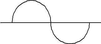
Drawing 1
Fundamental Root Frequency 60 Hertz
Since an applied voltage sinewave will cause a sinusoidal current to be drawn, systems which exhibit this behavior are called linear systems. Incandescent lamps, heaters and, to a great extent, motors are linear systems.
Some modern equipment is taking on different characteristics. Computers, variable frequency drives (VFD’s), uninterruptable power supply systems and electronic ballasts are some types of non-linear electrical loads. In these systems, the resistance is not a constant and, in fact, varies during each sinewave. This occurs because the characteristics of the load drawn by the equipment are not a constant. The resistance, in fact, changes during each sinewave. The power supplies of these systems usually contain solid state devices such as power transistors, thyristors, or silicon-controlled rectifiers (SCRs). These devices draw current in pulses.
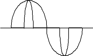
Drawing 2
The major difference between an AC source and a DC switching power supply of most electronic equipment is simply that it draws current only within short periods of time or (cycles) within the normal sine wave. This is how harmonic currents are introduced into the return or neutral of an electrical power distribution system.
As voltage is applied to a solid state power supply, the current drawn is (approximately) zero until a critical “peak voltage” is reached on the sinewave. At this peak voltage, the transistor (or other device) gates or allows current to be conducted. This current typically increases over time until the peak of the sinewave and decreases until the critical peak voltage is reached on the “downward side” of the sinewave. The device then shuts off and current goes to zero. The same thing happens on the last 180° of the sinewave side with a second negative pulse of current being drawn. The resulting current is a series of positive and negative pulses, and not the true, smooth 60-cycle sinewave drawn by linear systems. Some systems have different shaped waveforms, such as square waves. These types of systems are often called non-linear systems. The power supplies which draw this type of current are called switched mode power supplies.
That is, one can create a series of sinewaves of varying frequencies and amplitudes to mathematically model this series of pulses. These are multiples of the fundamental frequency, 60 hertz. These multiple frequencies are called harmonics. The second harmonic would be two times 60 hertz,are called or 120 hertz. The third harmonic is 180 hertz and the fifth would be 300 hertz and on. In the typical three-phase power systems, the “even” harmonics (second, fourth, sixth, etc.) cancel. In these systems dealing with the “odd” harmonics is the challenge.
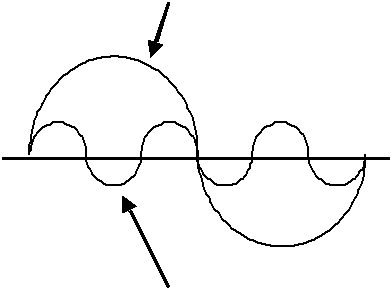
Drawing 3
This figure shows the fundamental (60 Hz) and the third harmonic (180 Hz). As you can see, there are three cycles of the third harmonic for each single cycle of the fundamental. These two waveforms will be additive, as it flows it results in a non-sinusoidal waveform. Peaks will start forming that are indicative of the pulses drawn by switch mode power supplies. If one adds in other harmonics, one can model any distorted periodic waveform, such as square waves generated by UPS or VFD systems. It’s important to remember these harmonics are simply a mathematical model. The pulses or square waves, or other distorted waveforms are what one would actually see if one were to monitor an oscilloscope on the building’s wiring distribution systems. True RMS testing equipment is available and qualified testing facilities are available that can effectively measure these currents. These current pulses, because of Ohm’s Law, will also begin to distort the voltage waveforms in the building. This voltage distortion can cause premature failure of electronic devices.
On three-phase systems, the three phases of the power system are 120° out of phase. The current on phase B occurs 120° (1/3 cycle) after the current on A. The current on phase C occurs 120° after the current on phase B. Because of this, 60 hertz (fundamental) currents actually cancel on the neutral. If there are balanced 60 hertz currents on three-phase conductors, neutral current in theory and on the meters will be zero. It can be shown mathematically that the neutral current (assuming only 60 hertz is present) will never exceed the highest loaded phase conductor. Thus, overcurrent protection on phase conductors also protects the neutral conductor, even though there is no overcurrent protective device in the grounded or neutral conductor. This is in compliance with NEC® Section 240-22, which says one should not connect an overcurrent device in series with any grounded conductor of the system.
When harmonic currents are present, the third harmonic of each of the three-phase conductors is exactly in phase. When all of these harmonic currents return together on the neutral, rather than cancel, they actually add and can result in more current on the neutral conductor than on phase conductors. These neutral conductors, in effect, are no longer being protected against overcurrent by the overcurrent device (breaker or fuses) on the circuit. These harmonic currents will create heat, which, over a period of time, will raise the temperature of the neutral conductor. This temperature increase can overheat the associated conductors in the same enclosure and cause insulation failure. These harmonic currents also can cause sources (such as transformers or generators or converter windings) which supply the power system to overheat. This is the most obvious symptom of harmonics problems: overheating neutral conductors and transformers. This overheating is largely related to the “skin effect.” Simply stated: currents flowing at higher frequencies will not utilize the total conductor property or total circular mil area, but will flow on the skin of the conductor, creating heat. Some symptoms include:
- Heat in the conduit of wiring systems
- Computer malfunctions and data loss or errors
- Insulation degradation
- Nuisance tripping of circuit breakers
- Several solutions are available to address these symptoms:
Oversizing Neutral Conductors:
In three-phase circuits with shared neutrals, it is common to oversize the neutral conductor up to 200% when the load served consists of non-linear loads. For example, many panelboard manufacturers build a 200% neutral bus rated panelboard for these applications. Most manufacturers of office furniture systems provide a No.10 AWG conductor with 35 amp terminations for a neutral shared with the three No.12 AWG phase conductors. In feeders that have a large amount of non-linear load, the feeder neutral conductor and panelboard bus bar should also be oversized. Section 310-15(b)(4)(c) considers the neutral (that is carrying these types of currents as a majority of the load) current-carrying conductors.
Using Separate Neutral Conductors:
On three-phase branch circuits, another method, instead of installing a multiwire branch circuit sharing a neutral conductor, is to run separate neutral conductors for each phase conductor. This increases the capacity and ability of the branch circuits to handle these harmonic loads. While this successfully eliminates the addition of the harmonic currents on the branch circuit neutrals, the panelboard neutral bus and feeder neutral conductor still must be considered
Oversizing Transformers and Generators:
The oversizing of equipment for increased thermal capacity should also be used for transformers and generators which serve harmonics-producing loads. The larger equipment can dissipate more heat effectively.
K-Rated Transformers:
Special transformers (K-Factor Transformers) are being manufactured to dissipate the additional heat caused by these harmonic currents. These transformers that are specifically designed to handle the effects of circuits and feeders with harmonic currents are being installed for old and new computer rooms and information technology systems.
Surge and Dip Filtering Equipment:
While many filters do not work particularly well at this frequency range, special electronic tracking filters can work very well to eliminate harmonics. These filters are presently relatively expensive but should be considered for thorough harmonic elimination.
Special Testing Equipment:
Standard clamp-on ammeters are only sensitive to 60 hertz current, so they only tell part of the story. New “true RMS” meters will sense current up to the kilohertz range. These meters should be used to detect harmonic currents. The difference between a reading on an old style clamp-on ammeter and a true RMS ammeter should give you an indication of the amount of harmonic current present.
Grounding Conductors: Your Safety Insurance Factor
Often times when the quality of the power is considered dirty, recommendations to install “isolated” equipment grounding conductors, also referred to as “separate grounds” or “clean grounds,” are the course of action. The rules for installing a separate isolated grounding conductor are covered in detail in the NEC® in Section 250-96(b) and 250-146(d) (See Figures 1 and 2 below). The Fine Print Note following each of these sections explains that the use of this method for the reduction of electrical noise in the grounding circuit does not relieve the requirement for grounding the raceway system and outlet box. The use of supplemental grounding electrodes often is in the plan for each electronic piece of equipment. While the National Electrical Code® allows this “supplemental electrode” in Section 250-54, it does not in any way relieve the requirement of the proper connection of an equipment-grounding conductor. “The earth shall not be used as the sole equipment grounding conductor.” Grounding conductors are required by the National Electrical Code® in the United States and by most other major electrical codes in the world. No matter what they are called, these conductors serve the same purpose. Grounding conductors connect all of the non-current carrying parts of the electrical system or any metallic parts in the vicinity of the electrical system together. This part includes conduits, enclosures, supports and other metallic objects. [See Figure 1 and Figure 2]
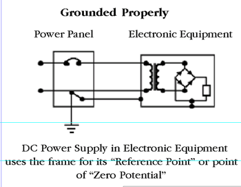
Figure 1
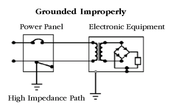
Figure 2
This grounding system has two purposes:
1. Safety. The grounding conductor system provides a low impedance path for fault currents to flow. This path must have three important characteristics. The path must be permanent and continuous, have lowest impedance possible, and the capacity to conduct safely any current imposed on it. This allows the full current to be detected by overcurrent protective devices (fuses and circuit breakers), safely clearing the fault, quickly eliminating shock hazards to persons and protecting property. See NEC® Section 250-2(d).
2. Power quality. The grounding system allows all equipment to have the same reference voltage. The electronic power supply in electronic equipment uses the frame of the equipment for the reference point. This is where the ac equipment grounding conductor and the electronic equipment grounding circuit come together. (See figure below.) This helps the facility’s electronic equipment operation and helps prevent the flowing of objectionable currents on communication lines, conduits, shields, and other connections.
To examine the safety issue more closely, consider the following system: a power system consisting of a voltage source (transformer or generator) connected to a disconnect and a panelboard. An appliance is fed from this panelboard. When the circuit is formed current flows in the circuit allowing the appliance to operate. The grounding conductor connects the frame of the appliance to the panelboard enclosure and to the service enclosure. This enclosure is connected to the grounded conductor (often the neutral conductor) which, in turn, is connected to the grounded terminal of the transformer. If a ground-fault occurs, the grounding conductor connection allows current to flow. This current will be much greater than the normal load current and will cause the circuit breaker to open quickly. This safely clears the fault and minimizes any safety hazard to personnel. Suppose the grounding conductor is not connected properly or is interrupted. If a fault occurs, little or no current will flow in the grounding conductor since the circuit is interrupted. This opened grounding conductor could be caused by a grounding prong illegally cut off a cord cap, a loose connection, a conduit which is not connected properly or many other causes. This fault leaves the frame of the appliance energized. Should someone touch both the appliance and the building steel, another piping system, or possibly even a wet concrete floor, the circuit would then be completed in current flow through the body, injuring or killing the person. The National Electrical Code® recognizes the use of certain raceways and cables as equipment grounding conductors. Many designers today do not believe that using steel conduits is adequate for this use. Conduit has connections every ten feet and often low-grade, cast-metal couplings and connectors are used. The secondary benefit of this copper grounding conductor is it will provide an equipotential plane for all equipment connected to it. This often makes the so-called isolated grounding conductors specified by computer and other manufacturers unnecessary.
Article 250 of the National Electrical Code® sets up the minimum requirements for grounding and bonding of electrical power distribution systems. Article 250 took on a new look and feel for the 1999 Code cycle. First, it should be understood that all of the previous requirements in Article 250 are still in place as minimum requirements. Second, the article has been totally reorganized. The performance based requirements in 1996 Section 250-1 FPN 1 & 2 and also Section 250-51 have been written into the general requirements of Part A. The 1999 edition also continued its quest to migrate away from using the grounded conductor for grounding equipment downstream of a main bonding jumper at a service, or downstream from a bonding jumper at a separately derived system. This still is allowable in very few cases with several restrictions. The section on objectionable current flowing on the grounding system still exists in Article 250. It is worth a closer look. Section 250-6(d) deals with permissible alterations to stop objectionable current. This section explains that the provisions of this section should not be misunderstood as allowing electronic equipment from being operated on ac systems that are not grounded as required by Article 250.
Following the minimum requirements in the National Electrical Code® essentially provides for the safety aspect and purpose of chapter two (Wiring and Protection). By following the rules in Article 250 regarding properly sized grounding conductors, proper use of isolated grounding conductors, code compliant installation of supplemental grounding electrodes, and proper connections of both grounded conductors and equipment grounding conductors users can ultimately end up with one having the”best of both worlds” when it comes to power quality issues and most important safety concerns. These grounding and bonding topics are extensively covered in the IAEI Soares Book on Grounding (Seventh Edition).




Find Us on Socials