Neon lighting requires ignition of gas in processed tubing with higher voltages. Voltages in the required ranges are developed by transformation from a primary (low voltage) circuit input to a secondary (high voltage) output. The voltages are produced by appropriate neon transformers or power supplies. The supply chosen is directly related to three key factors, which include the size of tubing used, the type of gas contained within the processed tubing, and finally the length of tubing. The amount of tubing also has an impact on the number of transformers required for the installation. Placement of the transformer(s) or power supply can also determine the length of secondary (high voltage) circuit that must be installed from the supply to the neon tubing. This article picks up where we left off in the last issue and focuses on the general requirements for neon secondary circuit conductor installations from the high voltage hub or connection at transformer or supply to the first electrode in the tubing installation.
Secondary Circuit Wiring Methods
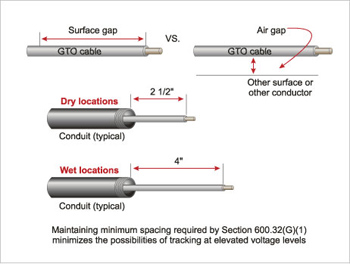
Figure 1. Minimum surface of conductor insulation distances (surface gap) requried at GTO cable points of emergence from conduit or tubing
An important point to emphasize here is that high voltage secondary circuit installations must meet the requirements contained in Part II of Article 600. Currently Section 600.30 indicates that Part II applies only to field-installed skeleton tubing. It should be understood that Part II is also necessary for application neon secondary circuit installations for signs and neon circuits other than field-installed skeleton tubing. It has to apply to those installations also because Part II contains the applicable rules for the neon tubing, electrode connections and secondary circuit conductors for field-installed skeleton tubing installations as well as other neon installations with secondary circuits over 1000 volts. There are proposals to revise Article 600 to correct this apparent hole in the Code. In reality, installers and inspectors are already applying the rules in Part II to secondary circuits over 1000 volts because that is where the rules are located, even though literally, the requirements of Part II of the article currently applies only to field-installed skeleton tubing installations.
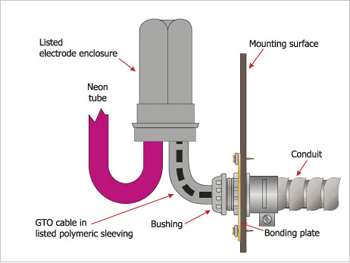
Figure 2. Listed nonmetallic point of transition and electrode connection showing mounting plate at wall surface and required sleeve material
High voltage circuit conductors must be installed to meet some basic Code requirements. Generally the high voltage conductors must be installed in a wiring method as specified in 600.32(A)(1). This section recognizes rigid metal conduit, rigid nonmetallic conduit, electrical metallic tubing, flexible metallic conduit, liquidtight flexible metal conduit, liquidtight flexible nonmetallic conduit, metal enclosures and other equipment listed for the purpose. These wiring methods of the conduit types are required to be installed in accordance with the applicable installation rules in Chapter 3 of the NEC which includes securing and supporting, use of listed fittings, and so forth, and must not be smaller than metric designator 16 (trade size ½ in.). Unlike standard electrical circuits, only one high voltage secondary conductor is permitted in a conduit or tubing.
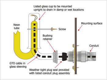
Figure 3. Listed glass point of transition and electrode connection showing conduit plug assembly and orientation for wet location installations
The high voltage circuit conductors are required to be insulated and listed as Type GTO (gas tube sign and ignition) cable rated for 5, 10, or 15,000 volts, and not smaller than 18 AWG. The minimum temperature rating must not be less than 105ºC (221ºF). GTO cable is listed under UL 814 and the requirements in the Code relative to these conductors are also requirements of the UL standard. It is important that care be taken when installing any electrical circuit conductors, especially high voltage circuit conductors. High voltage neon secondary circuit conductors are subject to higher stress levels, so the Code places extra consideration for sharpness of bends, and protection from physical damage are necessary for the installation.
(Isn’t it somewhat interesting that high voltage neon secondary circuit conductors are often installed where they do not even meet the minimum installation rules? It seems as though the branch circuit supplying the transformer is installed appropriately, but the secondary falls short of meeting the rules. This is unfortunate, but a reality. Installers and code enforcement share roles in assuring that these installations meet the Code minimum.)
The wiring method used for the neon secondary circuit installation must also be suitable for the environment in which it is installed. Simply speaking, if the secondary is installed in a wet location, suitable wiring methods and fittings must be used. This is a general requirement found in Chapters 1 and 3 of the Code.
Spacing and Length Limitations of the Secondary
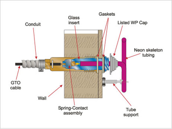
Figure 4. Anatomy of a listed neon tubing electrode receptacle showing weather cap required to be used where the tubing receptacle is exposed to wet locations
High voltage neon secondary circuit conductors must maintain a minimum spacing of not less than 38 mm (1 ½ in.) from each other and objects other than listed insulators or tubing. Where the conductors emerge from conduit or tubing in dry, damp, or wet locations, they must maintain a minimum length of conductor insulation. In wet or damp locations a minimum of 100 mm (4 in.) of insulation must remain on the conductor, and in a dry location a minimum of 65 mm (2 ½ in.) is required (see figure 1).
Length in any electrical circuits is related to capacitance in the circuit. A capacitor is simply two conductors separated by insulation (could be air). So when electrical circuits are installed, varying amounts of capacitance are built into these circuits. Keeping capacitance as low as possible is desired for high voltage neon secondary circuits, and this is accomplished by length limitations.
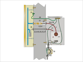
Figure 5. Cross-sectional view of a neon lighting system showing the secondary circuit wiring installed from the transformer to the electrode connection within the pan challel letter of the sign.
Section 600.32(J) provides a length restriction for neon secondary circuit conductors. Two maximum lengths are provided; one length for metallic conduit or tubing, and one for nonmetallic conduit. The length is from the high voltage terminal (hub) or lead connection measured to the connection at the first electrode in the tubing from each side of the transformer or supply. Basically for metallic conduit or tubing, the length is limited to conduit, the maximum length of which is 15 m (50 ft). The length restriction is related to keeping capacitance effects as low as possible in these secondary circuit installations. Intermediate jumpers between sections of tubing are required to be kept as short as possible as indicated in 600.32(J)(2). Chapter three in IAEI’s book, Neon Lighting provides more detailed information about the circuit characteristics of the high voltage secondary installations and the concerns.
Points of Transition
As the neon secondary circuit conductor and wiring approaches the tubing electrode connection point, a transition must be made to connect the GTO cable to the tubing electrode. This point of transition is where things seem to go amiss. There really is no reason this transition should be so difficult. It involves a little planning and knowledge of the parts or components suitable for this use. There are a few ways in which to accomplish this transition and meet the Code rules in the process. Remember 600.32(A)(1) requires the secondary conductors to be installed in one of the methods contained in that section, which includes “”equipment listed for the purpose.”” These are still secondary circuit conductors and the Code rules still apply. There are transitions of the nonmetallic types and the glass types that are listed for this purpose to make this task easy to accomplish (see figures 2 and 3).
An important consideration for the transition is the location. In a damp or wet location, the transition means and electrode connection must be suitable for the purpose (listed). Section 600.42 provides rules for such connections, and there are products available. It is common knowledge in the electrical industry that if a failure is going to happen, it generally happens at electrical connections; in this case, the point of transition. Care must be taken to meet the minimum rules and use materials or assemblies that are listed for the purpose within the limits of how they were listed to be used. Where glass transitions are installed in wet locations, an orientation (position) requirement must be followed. In dry locations, glass types can be installed in any position. See the manufacturer’s installation instructions for specific information. Particular attention must also be placed on tubing clearances and supports for the tubing and conductor within 150 mm (6 in.) of the connection to the electrode.
Electrode receptacles are another popular method often used as the point of transition between the secondary circuit conductor and the tubing electrode connection. These electrode receptacles are listed specifically for the purpose and must also be protected where the open end of the electrode receptacle is installed exposed to wetness. A listed cap must be used to close the opening between the tubing and the receptacle.
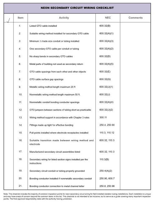
Neon checklists
Where a secondary wiring method terminates in a pan channel letter that is equipped with an appropriate face lens, the GTO cable is considered to be within an enclosure and is permitted to be exposed from the point of emergence from the conduit of tubing to the electrode connection. Be sure to observe the minimum spacing requirements contained in 600.32(E) and (G)(1) and (2) in this location and also at the conductor entry to the transformer enclosure(s) when making electrode connections in each location.
Figure 5 and the checklist for neon secondary circuit wiring installations from IAEI’s book, Neon Lighting are provided as a guide. Complete information and details related to these secondary circuits can be found in the book, including the applicable Code rules.
Always check with the local authority having jurisdiction for any local rules in addition to the minimum requirements of the NEC.