Introduction
In the very early days of electrical power generation and transmission (the 1890s), George Westinghouse and Thomas Edison battled it out to see which power generation/transmission system, alternating current (Westinghouse) or direct-current (Edison), would become the nation’s primary electrical power distribution system. Westinghouse won this early war of DC (direct current) versus AC (alternating current). That is the primary power generation and distribution system used throughout the United States and most of the rest of the world. This early victory was primarily due to the ease of changing voltage levels in AC systems using transformers, and at the time, there was no easy way to do the same with DC systems. Although early advocates of DC worked on methods of transforming DC voltages to higher levels, the complexity of using various motor-generator sets was not cost-effective, durable, or practical.
However, in recent decades, the development and application of high-current, high-voltage solid-state electronics (transistors and thyristors) are changing the picture. These solid-state devices can and are being used in various switching modes to make DC-to-DC converters and DC-to-AC converters, and AC-to-DC conversion devices.
At the high voltage end of power transmission, there are 800 kV (800,000 volts) DC transmission lines installed and operating. Devices have been demonstrated in the laboratory that may allow future transmission lines to operate at 1100 kV (1,100,000 volts) (photo 1). The transmission of electrical power at high direct-current voltages results in significantly lower losses than the transmission of electrical power using alternating current. And the use of direct current allows easier coupling and synchronizing of separate large transmission networks.

At the other end of the voltage spectrum, our computers, printers, clocks, LED lights, and other electronic devices in our homes operate for the most part on direct current, which has been transformed down from the normal distribution voltage of 120/240 V alternating current to levels less than 15 volts direct current in these devices or in a switching power supply at the plug (wall wart).
In years past, fluorescent lighting systems in stores have used electronic ballasts that would accept either AC or DC inputs. These lighting systems were powered by direct current from a roof-mounted PV system when there was sufficient energy from that source. At night or in cloudy weather, the AC power from the utility powered the lighting system. The changeover from AC to DC power and back was seamless.
If direct current at appropriate voltages were readily available in our commercial, industrial, and residential locations, significant efficiency, and cost benefits would be accrued. Such a DC transmission and distribution system, as well as premises use of direct current, is the wave of the future. There are some industrial applications already using DC power. End-use devices (e.g., variable speed drives and appliances) that can operate on dc power from a premises wiring system will be developed as dc microgrids, and nanogrids start being installed in first industrial, then commercial, and finally residential buildings.
The Basics
Various organizations, including manufacturers, universities, and specifically tailored groups devoted to the application of direct current to devices in our daily lives, are deeply involved in the research, study, and application of DC circuits, DC devices, and DC microgrids. One such organization is the Emerge Alliance (https://www.emergealliance.org/).
The Emerge Alliance has already issued several standards relating to DC microgrids and DC nanogrids. It is working with several other organizations, such as the Institute of Electrical and Electronic Engineers (IEEE), to develop standards for telecommunications systems, campus/neighborhoods/community microgrids, and residential applications.
The National Fire Protection Association (NFPA), as the publisher of the National Electrical Code (NEC), has been developing and including requirements for direct-current circuits and DC microgrids in the more recent editions of the NEC.
Looking Deeper
NEC Requirements for DC Circuits, DC Equipment, and DC Microgrids
The 2017 and the 2020 editions of the NEC have numerous references to DC circuits and systems. The following paragraphs present a list and, in some cases, a brief summary of the various requirements in the NEC that address DC systems, equipment, and circuits.
In Article 100, the neutral point is defined as the midpoint (in voltage between the positive and negative conductors) of a 3-wire DC system. Exhibit 100.14 (in the 2017 NEC Handbook) shows an example using a 3-wire DC system derived from a battery bank. This midpoint is connected to a conductor like the neutral conductor in a 240/120 VAC system.
Section 210.5(C)(2), Branch Circuits Supplied from Direct-Current Systems, establishes identification requirements in terms of marking or color coding for these DC circuits and sizes 4 AWG and larger and sizes 6 AWG and smaller. Ungrounded 4 AWG and larger conductors shall be identified by polarity at each termination, connection, or splice point. For positive ungrounded conductors, the options include:
- A continuous red outer finish; a continuous red stripe marked on a conductor of color other than green, white, gray, or black,
- An imprinted plus sign (+) or the word positive or POS durably marked on the insulation of a color other than green, white, gray, or black and repeated at intervals not exceeding 24 inches or,
- An approved permanent marking such as shrink tubing at all terminations, connections, and splice points with imprinted plus signs (+) or the word positive or POS durably marked on the installation of a color other than green, white, gray, or black.
A similar marking system shall be used on ungrounded negative conductors, except the primary color will be black, and the underlying insulation cannot be red, green, gray, or white.
It should be noted that there are and have been numerous off-grid, stand-alone DC electrical systems in dwellings that should be using these color codes for DC conductor identifications but probably have not. The “rule” that was used in the past has been “red for positive and black for negative,” and the NEC carries this requirement through with additional requirements.
Anticipated Nominal Direct-Current Voltage. Some of the working groups establishing and writing standards for these direct-current microgrids and DC circuits are working towards a nominal voltage of 380 V line to line (positive to negative). There is some probability that this will be a bipolar system with a midpoint connected to earth, thereby making the line-to-ground voltages a nominal 190 V. This has some impact when we look at Section 210.6(D)(3) which may pose limitations or requirements on the installation of luminaires (incandescent, fluorescent, and LED) in DC systems.
Section 215.12, Identification for Feeders, addresses the identification of ungrounded feeder conductors supplied from direct-current sources. The colors and marking requirements for both small and large conductors are like those required by branch circuit conductors in Section 210.5.
Section 240.15(B)(4), Overcurrent Protection, establishes requirements for using circuit breakers as an overcurrent protection device in DC circuits. There is an allowance for single-pole circuit breakers rated 125/250 volts DC with handle ties to be used when the line to ground voltage does not exceed 125 volts. However, as mentioned above, the line-to-ground voltages on these DC microgrids may be 190 V, thereby requiring a circuit breaker with a higher voltage rating. Although direct currents are harder to interrupt, it is anticipated that DC load centers will be developed that are not overly large.
Section 250.6(E), Grounding and Bonding DC circuits, discusses the requirement for providing isolation when there are objectionable DC ground currents from cathodic protection systems.
Exception No. 3 to Section 250.142(B) in the 2017 NEC concerning DC load side grounding has been removed from the 2020 NEC.
Article 250, Part VIII, Direct-Current Systems, addresses numerous requirements relating to the grounding of DC systems. As applied to a bipolar 380 V DC microgrid system, Section 250.162(B) requires that this system be grounded, and this would typically be the midpoint conductor. Section 250.164 indicates that the point of connection for grounding in a DC system will depend on whether the source of the DC currents is on the premises or off the premises. In either case, the source may be used as the grounding connection location. In an on-premises source, alternatively, the first system disconnecting means or overcurrent device may be used or other equipment listed and identified for equivalent system protection.
Section 250.166 specifies the required size of the direct-current grounding electrode conductor. These requirements are like those found in other sections of Article 250 dealing with the size of the AC grounding electrode conductor based on the type of the grounding electrode with minor differences.
Section 250.167 addresses the requirement for direct-current ground fault detection. Ungrounded DC systems are required to have ground fault detection, but ground fault detection is only permitted on grounded DC systems.
Section 250.168 discusses the sizing and connections requirements for the system DC bonding jumper and where the equipment-grounding conductors are to be connected to the DC grounding electrode conductor. Section 250.169 addresses the grounding of ungrounded direct-current separately derived systems.
Section 393.45 should be reviewed to determine the requirements for reverse polarity protection where low-voltage direct-current power systems are used for suspended power distribution systems.
Section 404.14(B) establishes limits on the use of general use snap switches (remember those?) with AC and DC ratings when connected to various loads.
Sections 408.3(E) and (F) discuss the bus arrangements and markings for various types of DC systems.
Section 410.134 requires that luminaries installed on DC circuits have auxiliary equipment designed for DC operation and the luminaries be marked for DC operation.
Table 430.12(B), Sections 430.22(A) and 430.29, and Table 430.247 establish various requirements for direct-current motors.
Section 445.12(E) lists overcurrent protection requirements for three-wire, direct-current generators.
Article 480 covers the numerous requirements for storage batteries which are direct-current energy storage devices
Section 522.28, Control Circuits in Wet Locations, establishes voltage limits for DC circuits in some applications and locations.
Section 530.64, Direct-Current Switchboards, establishes several requirements related to the use of direct current in switchboard applications.
Article 668, Electrolytic Cells, has several sections that deal with the direct-current connections to these cells.
Article 669, Electroplating has several requirements associated with direct-current circuits.
Integrated Electrical Circuits, Section 685.12 permits two-wire direct-current circuits in integrated electrical systems to be ungrounded.
Article 690, Solar Photovoltaic (PV) Systems, has numerous requirements that are based on the direct-current output of PV modules. These requirements have been discussed extensively in previous articles in this series which are archived at www.IAEI.org.
Article 691, Large Scale Photovoltaic (PV) Electric Power Production Facility, covers the documentation requirements on the direct-current operating voltage requirements for PV systems greater than 5 megawatts that are not under the direct control of a utility.
Article 692, Fuel Cell Systems, has requirements for direct-current circuits where those circuits are external to the fuel cell.
Article 694, Wind Electric Systems, has requirements where the direct-current circuits are external to the turbine.
Article 712, Direct Current Microgrids, will find significant application as these DC microgrids find their way into industrial, commercial, and dwelling applications. This relatively short article will undoubtedly be expanded in future editions of the Code as these applications proliferate. The solutions to real-world installation issues must be codified to ensure the uniform safety of these systems.
Direct-Current Microgrid Research at New Mexico State University.
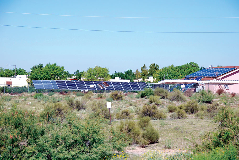
The Southwest Technology Development Institute (SWTDI) at New Mexico State University (where the author has worked for thirty-two years) was established in the early 1980s as a partnership between New Mexico State University and the US Department of Energy (see lead-in photo). The facility was dedicated to applied research on photovoltaic (PV) power systems. Although it ceased formal, fully-occupied operation in about 2013, the facility, under the author’s supervision, continues to produce about 40 to 50 kW of utility-interactive energy from the installed PV systems. Portions of the facility are now being converted to DC microgrid research, and the author supervises electrical and mechanical engineering students in the initial stages of the conversion process. It might be instructive to note some of the issues that are being addressed in dealing with this 380 VDC microgrid research facility.
The 380 VDC Bus. For this facility, it was decided to install a 100-amp, nominal 380 VDC main bus running between workstations in two adjacent buildings. At this current level, 1 AWG conductors were selected, and the design assumed that there would be a midpoint conductor between the positive and negative 380 VDC conductors, which, according to Code requirements, will be grounded, but not necessarily solidly grounded [712.52(B)].
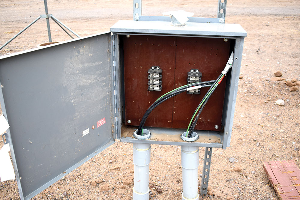
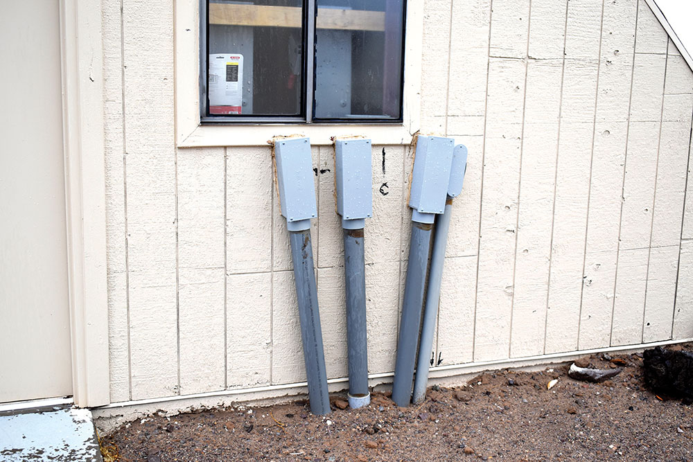
Four PVC conduits were installed underground between the buildings. The conduits consisted of one 3-inch PVC conduit for the main 100-amp 380 VDC bus. Another 3-inch conduit was installed, also with 100-amp conductors, to allow for fault testing of equipment being designed. There is a termination point in an outdoor metal enclosure for this fault test bus (photo 2). A third 3-inch conduit was installed for a 100-amp 120/240 VAC bus between the buildings to allow for the possibility of connecting AC loads to the DC bus after DC to AC conversion. The fourth PVC conduit was sized at 2 inches and was reserved for data acquisition circuits, communication circuits, and a local area network cable. PVC conduits below ground are Schedule 40; above ground-Schedule 80. See photo 3.
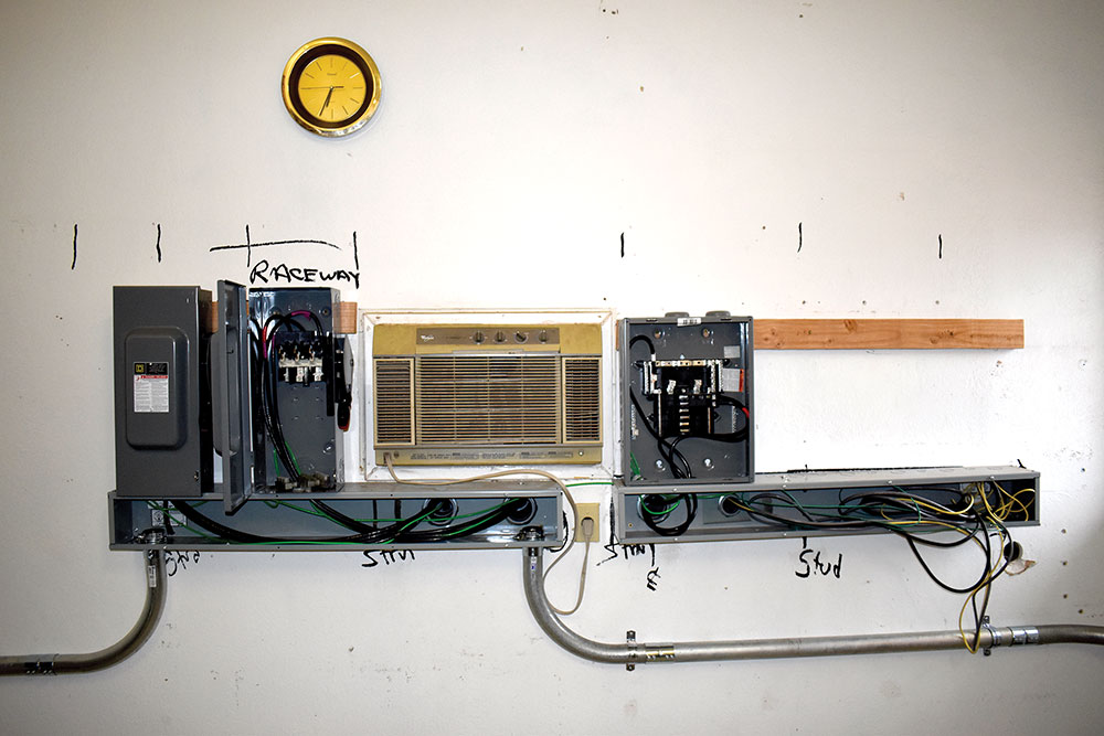
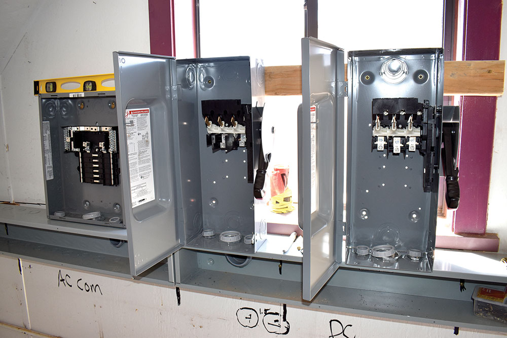
The PVC conduits, as they enter the buildings, are terminated in two 6 x 6″ steel raceways with the conduits containing the 100-amp 380 VDC circuits in one raceway and the AC circuits and the communication circuits terminating in a second raceway (photo 4). Each of the two 380 VDC circuits between the two buildings will terminate in each building with a 100-amp DC rated disconnect. It should be noted that these 100-amp DC-rated unfused (or fused) disconnects are quite large. While they may be suitable in industrial and some commercial installations, the industry will have to develop and market much smaller disconnects for the residential market. This disconnect allows independent operation of each building and will have a lockout-tagout system to ensure operator safety. The 100-amp AC circuit between the buildings will terminate with a 100-amp load center in each building. See photo 5.
From the metal raceways, 2-inch EMT conduits were routed to four workstations in one building and a single workstation in the second building. These will carry the 380 VDC bus conductors. EMT was selected based on the increased safety provisions of this metal tubing, which is exposed and runs along the interior walls of the building. Connections through the workstations to the 380 VDC bus may be from one or more PV systems, an energy storage system, other sources such as a hydrocarbon-fueled engine-driven generator or a wind turbine. DC-to-DC converters or AC-to-DC inverters will interface each of these sources (or loads) to the 380 VDC bus. Students will be designing and testing the interface devices.
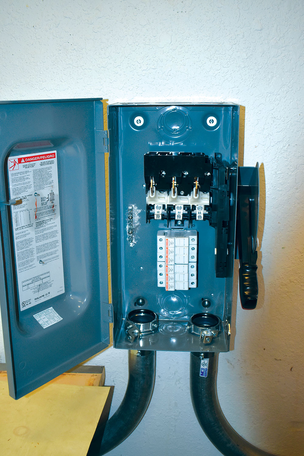
Disconnects and Overcurrent Devices. DC-rated 600-volt disconnects (safety switches) are common in 60-amp and 100-amp configurations. The 60-amp disconnects were chosen for each workstation location to allow the connection of two 30-amp fused input/output jack panels for connection of either loads or sources up to 30 amps per input. As noted previously, these disconnects are large and would probably not fit readily into the residential/dwelling environment.
While these DC-rated 600-volt disconnects are available in fused configurations, many of the more common RK-type fuses have only a 300-volt DC rating. There are indicating and solid-state fuses that can be used with a 500-volt dc rating, but it was decided to install unfused disconnects. Midget, finger-safe fuse holders were installed in the space normally occupied by the larger fuses (photo 6). Since the exact nature of the ground fault detection system is unknown at this time, all three conductors (positive, negative, midpoint) of the 380 VDC bus were switched, and each of the three conductors was fused in each of the two input/output circuits for each workstation.
While the input/output wiring and fuse holders are rated at 30 amps, fuses that will be used will be selected based on the continuous current rating of the input source or the output load-up to a maximum of 30 amps.
Laboratory operating procedures will be established to ensure that no conductor or disconnect will be subjected to continuous currents of more than 80% of rating.
A PV system with a DC output of a nominal 400 volts at about 8 amps (STC ratings) will be connected to the input of a DC-to-DC converter. That converter will not only peak power track the PV array but also maintain a 380-volt direct current output required by the 380 VDC Bus. The PV system overcurrent protection requirements of using overcurrent devices listed for PV applications [690.9(B)] determined that midget fuses with that listing be used.
Connection to a battery system (voltage TBD) is planned for the microgrid system. A programmable bidirectional DC-to-DC converter will control the charging and discharging of the battery while maintaining a relatively stable 380-volt bus voltage. The battery midpoint (+/- 190 volts) may also be used (with appropriate equalizing controls) to ensure that the positive and negative voltages to ground on the bus stay close to +/- 190 volts.
Summary
While there are some limited applications of DC microgrids, the industry is still in its infancy. Standards are being developed and published while research is being conducted on how to best implement the use of direct current energy sources for end-use industrial and commercial equipment and dwelling appliances. Some of the necessary disconnects and overcurrent protective devices are available, but new, smaller, more compact devices will be required to replace similar alternating current devices now in use. Everyone involved or potentially involved should keep abreast of developments in the field.