I remember many years ago working at a nuclear generating facility and being surprised that there was very little of the NEC being applied to the installation. It was mostly engineered design utilizing many IEEE Standards and it was only regulated by private inspection teams. The majority of the components were not listed/certified by a NRTL and, frankly, the installation was difficult for even a journeyman electrician to grasp as many of the NEC codes were not applicable to the installation. The structural building codes and special inspection requirements were not clearly understood or defined, and the IEEE standards used by the design engineers were not available for the electrician to read and digest.
With privately owned and built power generating substations, the same is true. Because of this, the AHJ needs to determine the level of compliance required and the appropriate standards to be applied. Some questions to ponder are:
- Will you require a recognized NRTL to field evaluate all unlisted/uncertified components?
- Who will monitor the medium/high voltage terminations?
- Will you require third-party verification of all VLF/ELF testing before energization?
- Who will review the relay settings at the control building?
- Who will perform the special inspections required by the IBC?
- Will you enforce OSHA requirements for restricted access?
- How do you determine NEC requirements and IEEE requirements (and if there’s a conflict, which requirement will prevail)?
- Should an inspector be dedicated full time to observe the installation?
These are just a few questions that you may want to address early in your discussions with the installing contractor. This can help avoid costly mistakes that usually lead to schedule and/or project delays, equipment modifications, and angry project leaders/contractors. Every AHJ wants to prevent these issues, and they can be avoided by using honest, open communication up-front from the start of the project.
This article will address the possible pitfalls in the construction and installation of privately owned generating substations as well as some other unique types of installations.
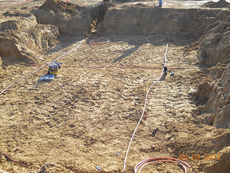
Underground Ground Mat
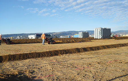
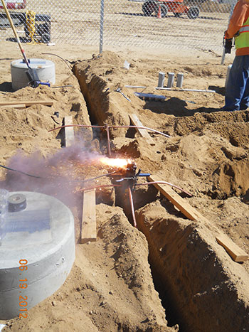
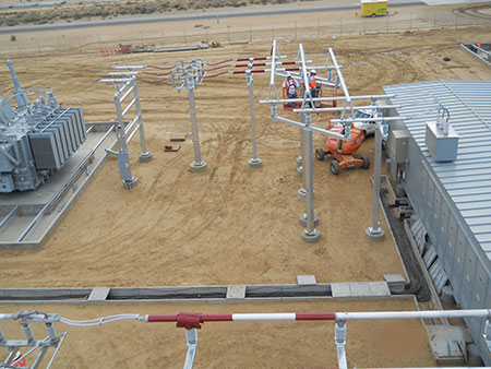
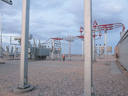
The underground ground mat conductors are installed in the substation soil to assist with fault clearing, equipment preservation, and personnel protection (step, touch, mesh, transferred voltage potential). The mat is trenched down 12 to 18 inches into the soil, and is spaced 10 feet to 20 feet apart in a grid pattern (see photos 3 & 4). Ground rods are placed at critical locations (such as at surge arresters, capacitors, and main transformers) spaced 20 to 100 feet apart, depending on the engineered design, and may extend several feet beyond the fence line of the substation. The conductor size will vary from 4/0 to 500 kcmil. The larger the area grounded, the lower the grid resistance, and the lower the ground potential rise (GPR). The engineer will be attempting to design around the GPR, and will utilize the IEEE-80-2013 standard as a reference (Guide for Safety in AC Substation Grounding) to design the following:
- Conductor size
- Grid pattern
- Ground rod placement
- Connections to foundations/anchor bolt cages
- Connections to equipment enclosures and switches
- Connections to ground rods, number used and length of rods
- Connections to the fence and the distance the ground mat will extend beyond the fence
- Soil characteristics (resistivity test)
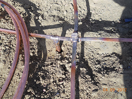
These components/conductors must be large enough to handle the high fault currents without excessive heating and melting. The Tables in the IEEE-80 standard provide the maximum allowable fault-current versus fault-current overtime. The engineer should pay special attention to this. As an example, a 4/0 conductor can withstand 42,700 amps without fusing (melting) for 0.5 seconds; however, at 5.0 seconds, it can only handle 13,500 amps. Connectors, either pressure-type or welded connections, that meet the IEEE 837 standard (Standard for Qualifying Permanent Connections Used in Substation Grounding) will satisfy all the criteria for mechanical strength, current carry capacity, corrosion resistance, and electrical conductivity. Additionally, soil conditions really drive the design of the ground grid and IEEE 80-2013-16.4 provides a 12 step process (with a block diagram) referencing all appropriate sections and equations to satisfy requirements regarding:
- soil conditions
- conductor size
- tolerable touch and step voltages
- conductor spacing (and rods)
- equations for resistance in soil (and computer analysis modeling)
- equations for only that portion of fault current that flows through the grid to earth
- analysis of GPR
- calculation of the mesh and step voltages done by analysis
- ‘if/then’ statement for progressing to step 10 or 11
- ‘if/then’ statement for touch/step voltage limits below tolerable limits
- ‘if/then’ statement for touch/step voltage limits above tolerable limits
- final review to eliminate hazards for transferred voltage potential and special areas of concern (see Clause 17)
Section 9 of the NESC (part 093E) and the NEC provides very little guidance regarding the installation of the ground grid. Therefore, the EOR (Engineer of Record) will need to provide the details in the approved drawings for this installation.
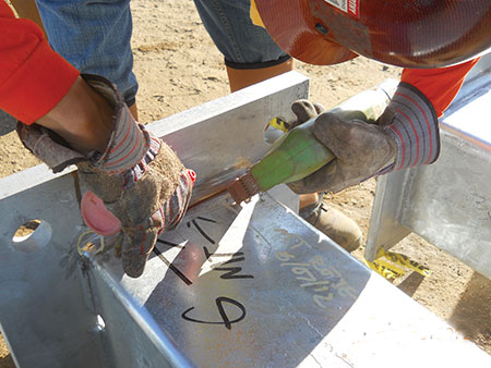
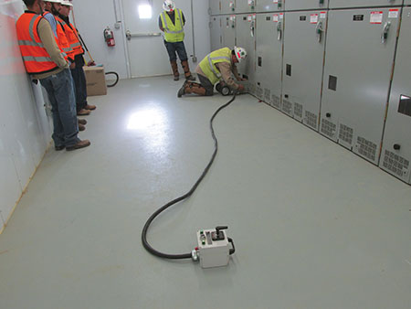
During your inspection, verifying that the work has been completed per the approved drawings is extremely important. This is especially true regarding all of the connections located underground (pressure and/or exothermic) (see photos 5 & 6). These should be verified by the inspector for proper depth and to make sure all appropriate tools/dies have been utilized. Be sure that the exothermic molds are discarded by the installer per manufacturer recommendations after repetitive use (see photos 7 & 8). It is also critical to inspect connections to rebar cages, rods, fence posts, gates, and control building. The grounding within and around the substation is extremely important to inspect to make certain there is quick clearing of high fault currents, and to ensure the safety and reliability of the system. The likely occurrence of future follow-up grounding inspections (after the installation is covered) is highly unlikely. This means you may be the last set of eyes to view the installation. No pressure, right? But as long as you make certain that the installing contractor is following good workmanship practices, this will ensure a safe installation.
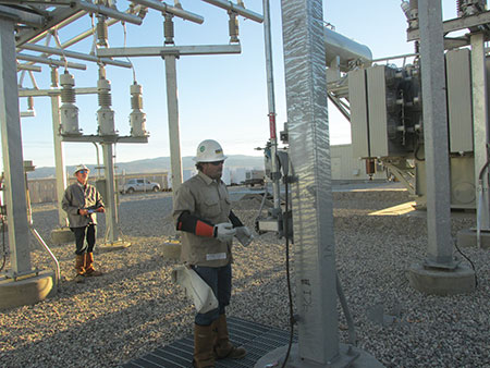
Additionally, remember the engineer may design to tolerable body current limits (see IEEE 80-2013-6 & 6.1 for the equations) where it is assumed that 99.5% of all persons can safely withstand the passage of current based on the magnitude and duration determined by a formula. As stated in the IEEE 80-2013, “it would not be practical to design against shocks that are merely painful and do not cause serious injury; that is, for currents below the fibrillation threshold” (< 60 mA). Keep this in mind when entering any substation (see photo 9). I always wear appropriate attire (Hazard Risk Category-2) with eight calorie flame resistant coveralls, along with boots that meet ASTM-F2413-11, leather gloves, hardhat and safety glasses; I don’t want the assumed equation to alter my life. I remember years ago when working in a high voltage substation I experienced a DC shock (50+ mA) when I touched the access doors to a de-energized GAS breaker. That experience drove home for me the importance of grounding and bonding. After I calmed down, the engineer installed a new metal grounded grate for the operator to stand on.
Fence Grounding
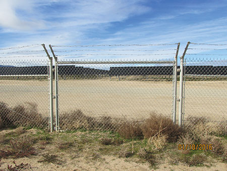
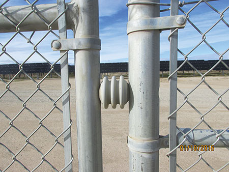
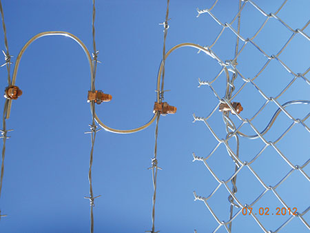
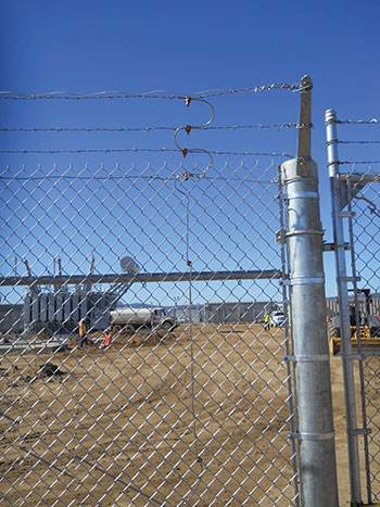
The metallic fence surrounding the substation may be grounded/attached to the engineered ground mat previously described. However, there may be cases where the Engineer of Record (EOR) may design an isolated fence attached to several miles of perimeter fencing to eliminate migration of fault current during an event (see photos 10 & 11). Again, the EOR should reference the IEEE 80-2013 standard to ensure all portions of the metallic fence, accessible to the general public, are calculated and designed within the calculated tolerable limits for touch and step potentials as touched on earlier. And NESC rules 092E and 093C6 can be followed for the connections to the barbwire strands, fence mesh (see photos 12 & 13), fence posts, and ground rod location at gates (swinging portion of the fence is grounded), as well as for typically flexible braided conductors, and buried bonding jumpers used across the gate entrance.
The IEEE 80-2013-17.4 standard provides five different test cases for fence grounding and utilizes computer analysis. The results and figures are provided via illustrations. The EOR will decide whether to attach (bond) the fence to the ground grid or keep it separate using ground rods. Or perhaps utilize as the ground the metallic posts used for support and set in concrete. This is very different from the NEC requirements where we have established size and depth requirements. It is recommended that at the beginning of the project, a components inspection be completed. By reviewing the drawings and inspecting the materials shipped to the site before installation, this will streamline the approval process for the hundreds of connections used.
When the grid and fence are completed, the approved drawings should detail the type of surface material to be placed within and around the substation. If this information is not included and there is no design and/or engineering justification provided, this is a safety issue. What is needed is a description of rock (the most common), asphalt or concrete and, if rock, the depth must also be provided. Rock depth is usually 3 to 6 inches and is placed within and around the perimeter of the substation. This rock may sometimes extend several feet beyond the fence to limit “step, touch, mesh, transferred voltage potential” discussed earlier. If this information is not included in the approved drawings I require a wet stamped, dated letter from the EOR stating the “current installation” meets the minimum requirements of the IEEE-80-2013. It’s important to make sure that it is stated as “current installation” because the design may change in the future.
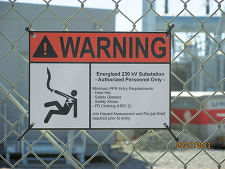
After the fencing is complete, NESC rule 110A requires a safety sign at each entrance and at each side of the fenced-in area (see photo 14). ANSI Z535 Safety Alerting Standards (comprised of six individual standards) provide information on the symbols/pictures, wording, size, colors and formats to be used for signage pertaining to warnings that describe the hazard, and provide recommended action to avoid the hazard. Additionally, during an inspection, I recommend that inspectors have the operator open all metallic gates and doors to limit unsafe exposures as described earlier.
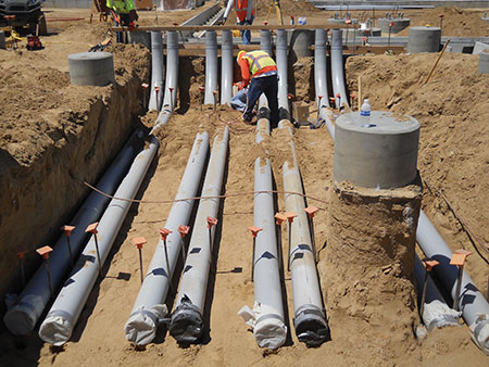
Underground electrical conduits
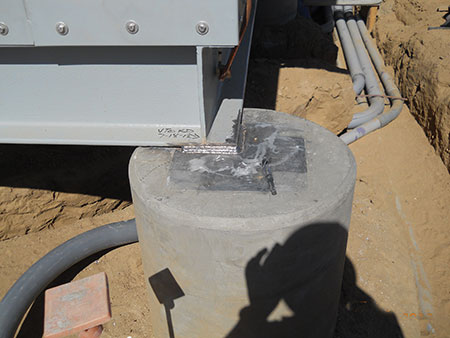
The underground electrical will usually consist of direct burial cables and/or PVC conduit at various voltages and currents; the drawings should indicate a unique identifier for each individual conduit and cable. By using the unique identifiers, this makes it easier to keep track of the approvals for each conduit and cable. Check the depths of the conduits and don’t forget that proper compaction is required and is usually called out in the geotechnical report requiring special inspection. Some installers will use 8 inch PVC (above and below ground) with large radius sweeps to enter the control building and/or substation. It’s important to remember that listed/certified 8 inch PVC does not exist and you will need to determine if a field evaluation is required (see photo 15). A best practice is to catch this at plan review to avoid schedule conflicts and project delays. Additionally, make sure to check the special inspection reports daily for drilled piers, rebar cages, structural concrete placement, welding and high-strength bolting. Your responsibility as the AHJ is to keep up with the activities of the project and review/approve all special inspection reports.
Support Structures
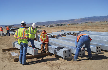
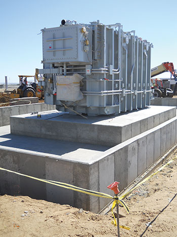
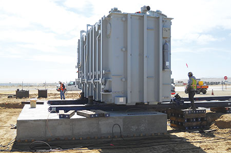
I will not dive into all of the micro details of the International Building Code (IBC), but it is important to keep in mind that the foundations and steel for equipment, like transformers and heavy static masts, are absolutely critical to ensure a safe installation. Some jurisdictions require approved fabricators for the steel support structures, or additional testing may be required (see photos 16 & 17) to verify that the welds (fabricated parts) meet the D1.1 welding code. And don’t forget that Section 2203 of the IBC requires the structural steel to have proper mill-certifications that meet appropriate ASTM Standards; identification must comply with the American Institute of Steel Construction (AISC 360). If not, testing is required. The pads and containments designed for the transformers are massive (see photo 18) and the over excavation/re-compaction of these areas will require special inspection (SI). The drilled piers also require SI. And when you are viewing this activity, don’t forget to use proper fall protection (i.e., use a harness, tie off, etc.). The installation can be several feet deep and may extend downwards up to 65 feet. So be careful. I have seen (on more than one occasion) a cave-in of the area surrounding a large drill where people were standing. As you might imagine, this caused a little bit of excitement for all involved. If you have a control building within the substation, it will be supported on drilled piers with steel imbeds (see photo 19) for welded attachment; again, all the activities need to be verified by SI as detailed in Chapter 17 of the IBC. This will require several SI inspectors verifying all of these activities on a daily basis.
Additionally, the EOR will detail the ground/bond connections (pressure and/or exothermic) attached to the steel reinforcement that will need to be inspected before concrete placement. Remember to pay special attention to the details specified in the drawings by the structural EOR. Many years ago, I was involved in a large bridge project in San Francisco where the structural EOR would not allow the use of exothermic methods of attachment to rebar or the use of plasma cutters on the structural steel. If this had not been paid attention to upfront, this would have triggered steel replacement, project delays and huge additional cost for replacements. Suffice it to say, the devil is in the details.
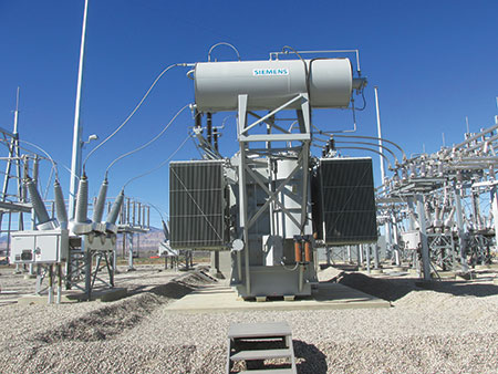
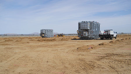
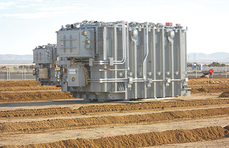
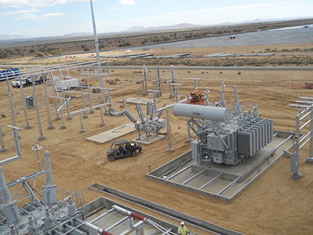
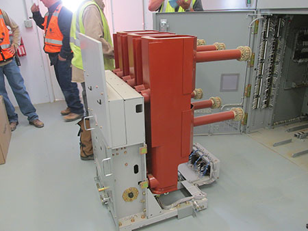
Equipment
Most of the medium/high voltage equipment that you see in substations will not be listed/certified by a recognized NRTL and you will need to determine if a third-party evaluation is required. Equipment such as main distribution transformers may take several weeks to a month to assemble (see photos 20 & 21) and have several hundred bolted connections that require some level of verification. A loose insulator or an improperly tensioned bolt for a reserve oil tank 40 feet in the air is a recipe for an unscheduled event that can be avoided by inspection. The air switches, ground switches (some may be motor operated) will require function verification during installation. The following is a partial list of components that will not be listed/certified that you will possibly need to involve a third-party NRTL, depending on your inspection experience:
- CTs, VTs
- Capacitors
- Sectionalizing cabinets
- Station transformers
- Gas breakers, or depending on the design, a control building with rack out breakers, and
- Medium/high voltage cable terminations
Any outdoor operator stations will usually have a grounded steel grate, which could be isolated (depending on the design) to stand on during manual operations. Be sure to look at this as part of your inspection. The control building will have step-down transformers for controls, panel boards at various voltages & currents, a DC system for the critical controls with battery backup, fiber optic patch panels, standby generator(s) and cable tray systems. These are a few of the items encountered and are similar to common industrial installations where you can apply the NEC generally for compliance. Lighting, access/egress, smoke/gas detectors, fire alarms, panic hardware, ventilation, and the heating/AC system, all will require some level of verification. There is more detail regarding this in the “Control Building” section below.
One other important thing to remember is that all of the medium/high voltage electrical Dead Break/Load Break BOL-T connectors, splice kits, and stress cones are not listed/certified by a recognized NRTL. With all of the bolted structural connections, electrical terminations, shipment of materials, and depending on the velocity of the project, it is recommended to employ a full-time inspector to oversee the installation and handle delivery inspections. Keep in mind that all bolted electrical connections will have a tensioning value and stacking order for nuts/bolts (grade 5), and Belleville (spring) washers.
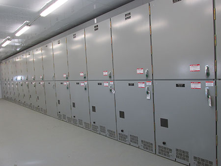
Control Building
The control building is the brain of the generating station and will be located within the substation boundaries. The components and controls are similar to an industrial installation and may contain some of the following:
- Revenue meters (and VAr meter)
- DC panelboards
- Battery bank for backup power
- Gas detectors
- Charge controllers
- Transfer switches
- Panelboards at various voltages
- SCADA systems (supervisory control and data acquisition)
- Remote switching for vacuum breakers, air switches and gas breakers
- Patch panels
- Heating & ventilation controls
- Cable tray & wire-way systems
- Step down transformers
- Medium voltage draw-out breakers with remote racking
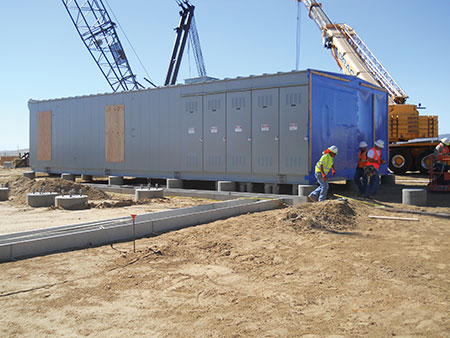
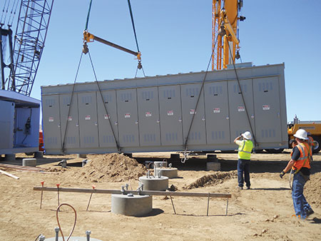
Some of the components will not be listed/certified by a NRTL and, depending on your comfort level and inspection experience, you may determine that it is necessary to require third-party field evaluation. One thing I have learned over the years is that most of these buildings are pre-fabricated and delivered to the site; and if the building is delivered in sections (see photos 22 & 23), then the additional field wiring installed should be inspected. I recommend inspecting the entire structure from the ground up. Some common issues encountered are the following:
- Undersized feeders
- Unlisted fine-stranded conductor
- Fine-stranded terminations in set screw lugs
- Overfilled wire-ways and cable trays
- Openings in the medium voltage breaker cubicles
- Improper working space
- Main bonding jumpers absent
- Transformers missing system bonding jumper
- Incorrect breakers installed in AC & DC panelboards
- Fiber optic cable in violation of Article 770.48(A)
- Battery bank in violation of Article 490.9
- Series rating for panelboard is incorrect
- All labeling is absent for disconnects, panelboards, controls
- Exit signs missing
- Service disconnects with two conductors under one terminal
- Feeders in violation of Article 300.3(B) & (B)(1)
- Overfilled raceway systems
- Twist lock receptacles installed (hole sawed) in four square blank covers
- Exposed 250V DC fuses
- Improper access/egress
- Medium voltage equipment is not NRTL certified
- Drawings do not match the installation
This is just a partial list of what you may encounter and, remember, the building itself should be plan-checked and verified as compliant to the building code. Some may have a State certification stating it was inspected by an independent third-party. However, careful consideration should be given as to whether to accept that certification based on the aforementioned list of common issues encountered. These issues will likely not be found through a third-party review.
Precast Concrete Trench
The Trenwa is where all the control wiring will be located and usually consists of all DC cabling. It is placed in the ground with removable covers (see photo 27) for easy access and future upgrades. [One of the few manufacturers of these precast concrete trenches is Trenwa, and its name has become common field terminology.] The removal covers extend its entire length from the control building out to the various equipment locations. It is important to check for proper soil compaction under this cable support system to ensure a good foundation. The cable will need to be verified as suitable for direct burial type and size verified to the approved control drawings. Checking the cables (and any and all materials) as they arrive to the site saves time and expedites the inspection process. The precast must be verified for the design load required for the project. For instance, will people be walking on this or will there be trucks passing over? The author has seen during night operations/shutdowns where vehicles have passed over these trenches and damaged the covers and conductors, which required additional shutdowns to remediate the issue caused by improper design and/or missing warning signs.
O & M building
Some privately owned generating substations (with certain technologies) may have an operations and maintenance (O&M) building, or they may be remotely controlled. As a little background regarding control and operation of O&M buildings, I have been involved with three substations that had O&M buildings associated with the installation while others were remotely controlled by private operators out of state. One common misunderstanding is that these power generating stations and substations are under the exclusive control of the utility. This is not true. The owner-operator is usually in full control as to the operation of the plant. For gas turbine type power plants, where the power can be quickly brought up and down, the utility can transfer control and run the generator as they need it. Allowing the utility to take control, of a solar plant for example, can cause more harm than good regarding controlling, adjusting, and shutting off inverters as well as maintaining the proper VArs (reactive power). The ability to shutdown the plant/substation is called a transfer trip, tripping the main breaker, but this is hardly ever used and is reserved for extreme emergencies. Voice communications between the owner and utility usually are sufficient in maintaining that control and the contracts with the utility dictate how the plant is to be operated. These buildings will have a feeder that originates from the substation and/or a separate service to provide the necessary power to work and observe the operation of the plant. If the site is generating its own power, operators may use one of the rooms as an operation center to control voltage, current, and frequency and to adjust reactive power (VAr). Some private owners will opt for remote control from their central control building located out of state.
Now that you have a little more of this background information, here’s what you need to pay special attention to when inspecting these sites. These buildings are inspected just like any occupied structure. They may be prefabricated or built with conventional construction and all of the requirements of the NEC and module building codes apply. You will have bathrooms, showers, kitchen, heating and ventilation, maybe sleeping quarters, and perhaps standby power systems—all require verification. And don’t forget to have your Fire Marshall inspect the fire alarms, test the sprinkler system, and check access egress pathways. Disabled parking, graspable hand rails, ramps, stairs, and the like all need to be verified. NESC Table 111.1 provides Illumination levels (may vary from your local codes) for the generating station interior, exterior and substation locations and the notes under the tables provide lots of detail regarding lighting location descriptions. Additionally, the NESC details the requirements and recommendations not covered in the NEC. These are broken down into 4 parts:
- General sections
o 01 (Introduction)
o 02 (Definitions)
o 03 (References)
o 09 (Grounding Methods).
- Part 1 Electric Supply Stations
- Part 2 Overhead Lines
- Part 3 Underground Lines
- Part 4 Work Rules
Some of the more unique sections and rules cover the following:
- Connection of the grounding conductor to non-shielded and shielded conductors/cables
- Grounding of messenger wires and guys
- Composition of grounding conductors
- Ampacity and strength for bare and insulated grounding conductors (designed for the short-time ampacity without affecting the design characteristics of the conductor and/or insulation)
- Ground resistance requirements
- Floors, floor openings, passageways, and stairs
- Working space for over 600 volts—several tables based on BIL (basic impulse insulation level), switching-surge or transient overvoltage
- Arrangement of switches in the substation and at poles
- Relationships between various classes of overhead lines and equipment
- Clearances for wires, conductors, or cables on the same pole
- Climbing space (for overhead lines)
- Working space (for overhead lines)
- Vertical clearance of conductors
- Wind and ice loading on an overhead line
- Manhole access opening dimensions and working space requirements
- Circuit identification at the termination location
- Unauthorized entry requirements for pad-mounted and other above ground equipment
- Rules for working on or near energized lines or equipment (see photo 28)
This is just a sampling of the uniqueness of the NESC; be sure to take note that the NESC is an IEEE Standard and is adopted by utilities, authorities having jurisdiction (as a supplement to local codes) and other authorities. And, in general, utilities in 49 of the 50 states use this standard with the exception of the state of California, which writes its own codes titled General Order 95 (overhead lines), General Order 128 (underground lines) and General Order 165 (inspection). We Californians have always liked to be different.
In summary, this article only scratches the surface of the many aspects to consider when inspecting these electrical systems. When you approach one of these types of projects for inspection, think of it as an iceberg – there may be much more below the surface than you can initially see. And these generating substations provide unique challenges with codes and standards that may be unfamiliar and/or different to the local inspector. However, with careful research and collaboration with industry experts, knowledgeable NRTLs, and a well-organized inspection team, these projects can be easily built, inspected, commissioned and operate safely/efficiently for many years with limited maintenance and/or unscheduled power events.
If this article has generated any additional questions and/or comments, please contact the author by phone 619-318-7310 or email at shinspections.inc@cox.net