Excitement is building in Arlington, Texas, as the Dallas Cowboys’ new stadium nears completion. The city of Arlington, Texas, with a population of 350,000 is now the home of two major professional sports teams, the Texas Rangers and the Dallas Cowboys. The Rangers’ ballpark and the new Cowboys’ stadium are centrally located within Arlington’s thriving entertainment district, along with other attractions such as Six Flags Over Texas and Hurricane Harbor.
In November of 2004, Arlington residents voted to accept a tax increase that committed $325 million towards the construction costs of the Dallas Cowboys stadium. Contractual agreements between the city of Arlington and Dallas Cowboys owner Jerry Jones paved the way for construction of the new stadium. The original estimated price tag for the stadium was set at $650 million. Ongoing changes and construction costs are projected to push the stadium cost over $1.1 billion before its completion in June 2009. HKS Inc., a Dallas-based architectural firm has designed the 2.3 million square feet, fully air-conditioned football stadium that will seat 80,000 to 100,000 fans and will have 300 suites. Manhattan Construction Company is the performing general contractor on the project.
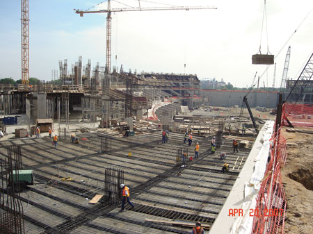
Photo 1. Ground level foundation steel work
Site development for the construction project required the purchase of 106 residential, commercial, and vacant land properties totaling 133.9 acres. It looked like a war zone in the months ahead as structures were demolished, land cleared, and 1.4 million cubic yards of dirt removed to make way for the utilities, foundation and the bowl of the stadium.
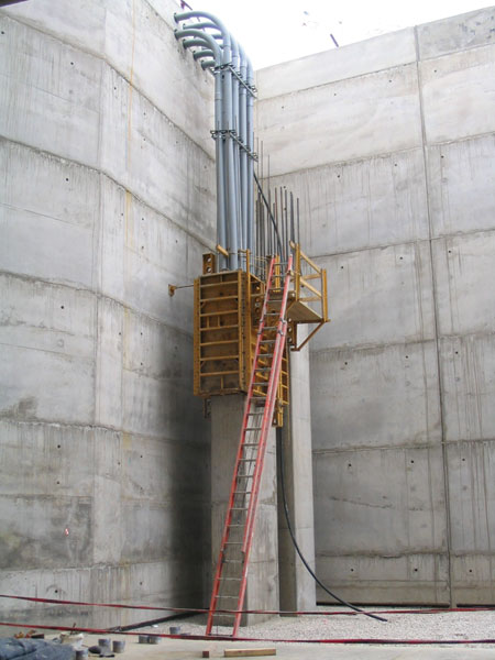
Photo 2. Utility primary conduits serving the stadium
Oncor, the electric utility delivery company, has supplied electric power to the stadium through two available power grid sources. Each 13.2 kilovolt power grid has two service feeders. The stadium can operate most loads on an individual service feeder from either power grid. An elaborate electrical utility switching program called the Vista System can automatically switch under a fault condition to another feeder within a 30-second time frame. The automatic switching process uses a series of switching arms with a 5-second rotation for each switching arm. The redundant electrical power grid and multiple service feeders provide reliability assurance in the event of a power outage.
The primary electric utility conductors have been installed within a utility easement that actually runs around the inside of the stadium. The oval utility easement inside the stadium can accommodate large vehicles up to and including 18-wheel semi trucks for maintenance and service of the utility equipment. Primary conductors serve utility transformers at four designated distribution areas of the stadium. The utility transformers step the voltage down to 4160 volts and 480/277 volts respectively, for electrical distribution throughout the stadium. The largest of the four utility distribution areas located adjacent to the oval utility easement, contains five 3750-KVA transformers and three 500-KVA transformers. It has been estimated that the diversified load for the stadium is approximately 24 MW. Each power grid has the capacity of handling a connected load of up to 50 MW.
Construction of the stadium began to pick up speed as concrete piers, foundations and the box abutments supporting the structural steel roof arches were poured. It is phenomenal when you realize how much structural support is installed for the arch trusses. There are four box abutments that support two structural steel roof arches. Each of the box abutments is 18 feet wide by 140 feet long and 71 feet deep of tightly webbed steel and concrete. The arch trusses stretch an amazing ¼ mile long and are the world’s largest single span roof structure. Rising 292 feet above the playing field, the roof arch trusses support a 660,800 square foot two-section retractable roof. The bi-fold retractable roof panels operate on rails with a rack and pinion drive system that can open and close the 256 feet wide by 410 feet long roof opening in less than 12 minutes. Power for the retractable roof panels is distributed through four 400-amp electrical panels that supply one hundred twenty-eight 7.5-hp, 480-volt, 3-phase motors.
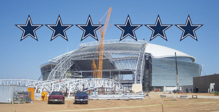
Photo 3. Retractable roof panel trusses and tracks
Over the center of the stadium, truss structures spanning between both roof arches support the world’s largest LED video display. A 1.4 million-lb. (1400 ton) LED video scoreboard suspended by cables approximately 90 feet above the playing field. The video scoreboard has nine floor levels and 2 sets of stairs that pass through to each floor level.
Electrical power to the scoreboard is supplied through two 1-MVA transformers with 4160-volt primary and 208-volt, 3-phase, 3-wire secondary, no grounded (neutral) conductor. There are twenty-four liquidtight (MC) metal-clad cables with three 350-kcmil aluminum conductors each, run from the 1-MVA transformers located in the steel trusses above, down below to the scoreboard. The twenty-four liquidtight MC cables extend down the steel support cables to the scoreboard and are secured by ½-inch diameter stainless steel clamps. One additional liquidtight MC cable with three 3/0 AWG copper conductors is brought down from a 75-KVA transformer to the scoreboard for standby power. The electrical distribution equipment is set on two levels within the scoreboard.
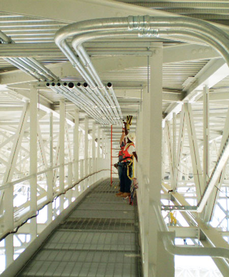
Photo 4. Feeder conduit installation on catwalks
Displays mounted on the scoreboard consist of two sideline displays that are 159′7″ wide by 71′ 4″ high with 10.5 million LEDs on each display. The two end-zone displays mounted on the scoreboard are 50′ 5″ wide by 28′ 6″ high with over 2 million LEDs on each display. All of the LED scoreboard displays are capable of displaying HDTV at 1080 p resolution. The high tech LED video scoreboard is made by Mitsubishi at a cost of $28 million. In addition, along the edge of the upper level is 1,986 linear feet of 4-feet-high LED display boards that contain almost 4 million LEDs. The ring of honor has 836 linear feet of 3-feet-high LED display boards with nearly 1.4 million LEDs.
One of the items that concerned fire department officials about the suspended scoreboard was the inability for rescue response teams to access and reach workers in an emergency situation. Periodic maintenance of equipment within the video scoreboard will have workers suspended at least 90 feet above the playing field. Original plans called for single man lifts which would not be sufficient for an emergency response. Fire department officials required the personnel lifts to be increased in size and capacity to provide a means of access and sufficient room for fire rescue team or paramedics, ambulatory bed and equipment. The personnel lifts on the scoreboard are now 5 feet by 8 feet with a 2000-lb. capacity. Each personnel lift has two motors, but only one motor is used at a time, the other motor is a redundant backup. The motors at each personnel lift are powered at 208 volts, 3-phase, 30 amps each. For life safety purposes, there are 18 telephones installed in the scoreboard for communications, a fire alarm system, standby power, and emergency lighting. The data, telephone, and fire alarm systems are served by fifteen, 2-inch liquidtight conduits extending down support cables to the scoreboard.
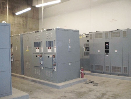
Photo 5. One of many 4160-volt electrical equipment rooms
Electrical service feeders off the secondary side of the utility transformers are distributed through sixteen electrical distribution switchboards inside the stadium and one electrical switchboard outside the stadium. Of the sixteen indoor electrical switchboards, ten of the switchboards are rated at 4160 volts; the other six indoor switchboards are rated at 480/277 volts. There are four 4160-volt, 2000-amp switchboards serving the 11,000-ton chillers and six 4160-volt, 1200-amp switchboards being utilized for general building power. All six of the 480-volt indoor electrical switchboards are rated 1200 amps and serve lighting, mechanical, and general building power loads. One 480-volt, 2000-amp outdoor electrical switchboard provides the power for all of the cooling towers. In the event of a fire, the fire sprinkler system utilizes a single 125-hp 480-volt, 3-phase fire pump for the entire stadium.
The end-zone glass doors standing at 120 feet high, and 180 feet wide are the world’s largest operable glass doors. Powered by only a single 480-volt, 60-amp circuit for each set of end-zone doors, they can open and close in 18 minutes.
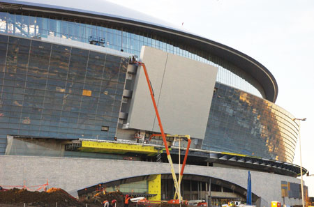
Photo 6. Outdoor LED display
I had an opportunity to talk with Dan Graham, senior superintendent for JMEG, the electrical contractor on the stadium project. Dan said that JMEG has six superintendents that work directly under him on the project. Each superintendent manages a group of electrical supervisors who are responsible for delegating project work areas and overseeing the journeyman electricians’ and apprentices’ electrical installations. At the peak of the project, JMEG had up to 309 electricians on site. The JMEG team has consistently performed well on the stadium project and is on schedule for its completion date despite all the changes that have been made.
With the scheduled completion date in June 2009, there are several noteworthy events already scheduled. The NBA all star game will be hosted at the stadium in 2010, the Super Bowl is scheduled to be hosted in 2011, and the NCAA Final Four will be hosted in 2014. Not a bad start for a stadium that is not yet completed. Despite a tough economy, pre-season ticket sales have been brisk and the 300 available suites are selling fast, as Cowboy fans look forward
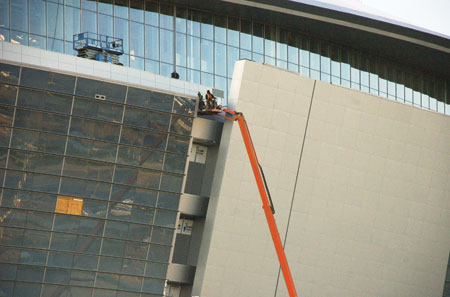
Photo 7. Glazier work on stadium exterior

Photo 8. Hydraulic bender set up for feeder conduit installation
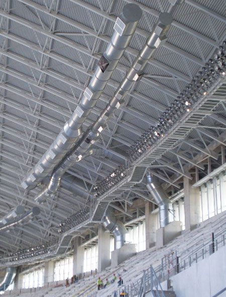
Photo 9. Sports lighting and mechanical duct work at domed perimeter
to the 2009 fall season in their new stadium. For further construction progress, updates, and information on the Cowboys stadium, please visit the city of Arlington website link at: www.arlingtontx.gov/cowboys
I would like to give a special thanks to David Ramage, Bureau Veritas; Fred Sivley, Manhattan project manager; Dan Graham, senior superintendent for JMEG; Andrew Shivley PE, electrical project manager for M-E Engineers Inc.; Mark Bringhurst, Oncor major projects manager; and Greg Walston, HKS Architects Inc., for their knowledge and assistance in providing information used in this article.