What is the purpose of a life safety system that fails in the event of an emergency? These systems are designed to help occupants safely evacuate a building during emergency conditions. Contractors, code enforcement agencies, and designers must understand the requirements of local, state, and national codes and standards that are developed in order to maintain this integrity.
A life safety system is comprised of building elements designed to protect occupancies and allow occupants to evacuate the building during emergencies safely. Emergencies can include anything from fires, natural disasters, terrorist attacks, or simply the loss of normal power. These building elements include alarm systems, emergency communications systems, fire suppression systems, ventilating equipment used for smoke removal, exit signs and egress illumination, and elevator control functions.
Electrical designers, contractors, and code enforcement agencies are directly involved with the installation of these systems electrically. But do you have a full understanding of the value of these systems? If not, maybe this article will help you with this subject. Life safety systems are the components that keep the occupants safe, but yet many people fail to understand the value and importance of these systems. Any time you are working directly with life safety systems, there should be a higher level of thinking and planning “outside of the box” to ensure the integrity of the systems not only during the initial installation but for the life of the systems.
This article will focus on the 2020 National Electrical Code (NEC) and the 2019 National Fire Alarm Signaling Code. It’s important to note that the National Electrical Code does not enforce when life safety systems are required, but rules and standards for the installation of these systems. The Building and Life Safety Codes establish requirements for when the life safety systems are required. Specifically, I will be focusing on the three most important factors in maintaining the integrity of life safety systems: emergency systems, fire pumps, and fire alarm systems.
Emergency Systems
Emergency systems are essential to safeguarding human life and keeping essential systems powered while occupants safely evacuate an occupancy. Emergency power systems are legally required by municipal, state, federal, and other codes or by the authority having jurisdiction. The Code intends to keep emergency systems isolated from other systems, create reliability, and maintain a hierarchy over other systems. These legally required systems are intended to supply, distribute, and control power for illumination, power, and other systems approved by the authority having jurisdiction (AHJ) to protect lives when the normal supply or source is interrupted. Emergency systems can provide an alternate source for exit signs, egress illumination, fire detection and alarm systems, ventilation equipment, elevators, fire pumps, and emergency communications systems in places of assembly where a large number of persons congregate.
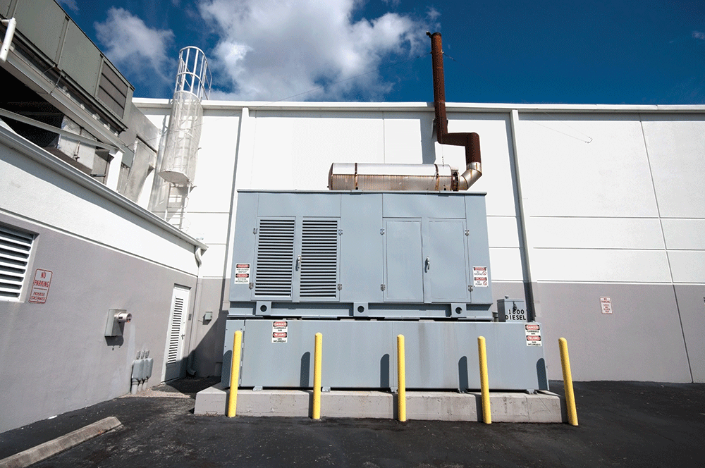
Emergency systems are required to be tested and maintained per Sections 700.3(A) through (E). The AHJ shall conduct the initial acceptance test to ensure the system functions properly. Section 700.3(B) states that the emergency systems shall be tested periodically on a schedule that is approved by the AHJ. Testing should be completed during times where the occupancy is under full-load conditions. These systems shall be maintained in accordance with the manufacturer’s instructions and industry standards. Written records shall be maintained by the owner of the tests and maintenance performed.
A new Section 700.3(F) was added into the 2020 NEC that specifies that if an emergency system relies on a single alternate source, a permanent switching means to connect a temporary source shall be connected into the emergency system. The switch used to connect a portable or temporary alternate source shall not require modification to the permeant system wiring, transfer within ten seconds, the connection point shall be marked with the phase rotation and bonding requirements, have the interlocking capability to prevent interconnection of power sources and shall annunciate once the permanent source is disconnected. This permanent switch is not required when the building is not occupied, when the processes protected by the emergency system is disconnected, temporary means can substitute the emergency system, or when another permanent alternate source is available.
Alternate power sources may feed emergency, legally required, and optional standby loads as long as the system is designed and installed to be able to hand the entire load or have load shedding capability. Per section 700.4(C), when allowing load-shedding, it must maintain the priority level of emergency systems as the top priority, legally required the second, and optional standby the last priority. If the alternate source does not have the capacity to maintain all three systems, it should be designed to maintain emergency power at all times.
Transfer equipment used for emergency power shall not feed any other loads. Transfer equipment shall be legibly marked and listed for emergency use. Audible and visible signals should be provided to allow notification if the transfer switch malfunctions, at times when the transfer switch is carrying a load, and when it is not functioning. This notification allows owners to know when the switch is not functioning properly.
Another new section was added to the 2020 National Electrical Code that specifies fire protection for assembly occupancies not less than 1000 people, buildings over 75 feet, and educational occupancies with over 300 people in section 700.10(D)(1) through (4). The feeder conductor from the alternate source shall be protected by one of the following:
- The cable or raceway is installed in areas protected by an approved automatic sprinkler system.
- The cable or raceway is protected by a listed electrical circuit protective system with a minimum 2-hour-fire rating.
- The cable or raceway is a listed fire-resistive system with a 2-hour-fire rating.
- The cable of the raceway is protected by a 2-hour fire-resistive system.
- It is installed in a cable or raceway that is encased with at least 50 mm (2 in.) of concrete.
The generator control wiring is required to be isolated from all other wiring not associated with the generator. The integrity of the generator control wiring is monitored for broken, disconnected, or wires that short out. The generator shall start if any of these three conditions exist.
Lighting and power for emergency systems shall be activated within 10 seconds once normal power is lost. Part IV of Article 700 in the NEC covers emergency system circuits for lighting and power. We must remember that the emergency system powers illumination for egress lighting, illuminated exit signs, and other luminaries that help occupants evacuate an occupancy during emergency situations. Section 700.15 states that no appliances or lamps shall be used for emergency use unless they are specified to. New Sections 700.16(A) through (D) were added into the 2020 cycle, and they create reliability standards for egress lighting. Section 700.16(B) states that the emergency lighting should be designed and installed so that failure to the illumination source shouldn’t leave any area that requires egress illumination in total darkness.
Egress illumination shall stay illuminated until normal lighting has completely returned when using high-intensity discharge lighting, not just when the normal source returns. Switches used for emergency lighting shall only be accessible to authorized personnel, and they should be properly identified; 3- and 4-way switches are not permitted for egress illumination. All manual switches shall be in a location convenient to authorized personnel; they shouldn’t need to put themselves in danger to access them. Emergency lighting can be supplied through dimmer systems in accordance with Section 700.23. During emergencies, the dimmer systems shall use a control bypass function and energize only the circuits supplying emergency lighting.
Fire Pumps
The purpose of the National Electrical Code is to practice safeguarding of persons of property, and typically the Code does this by protecting conductors at their ampacities, protecting against overcurrent, and ensuring that devices and equipment eliminate electrical hazards tripping circuits to stop energy from flowing, but with fire pumps everything changes. The Code recognizes the importance of ensuring that a fire pump’s functionality is more critical than protecting the wiring and equipment. A fire pump’s job is to supply water to a facility and maintain enough pressure for a suppression system to properly extinguish the fire and related hazards.
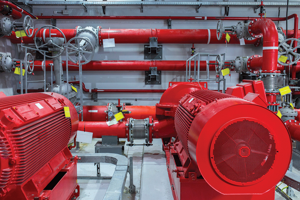
Article 695 entitled Fire Pumps in the NEC covers the electric power supplies, interconnected circuits, and the switching and control equipment used for fire pump drivers. Article 695 does not cover the performance, maintenance, and testing of fire pumps, related pressure pumps (jockey or makeup), or transfer equipment upstream from the fire pump dedicated transfer switch. Sections 695.3(A)(1) through (B)(2) outline the requirements for stable energy sources. This stability can be achieved by individual sources of electrical utility or an onsite power production facility located and protected from fire hazards. If determined that a single source is not adequate, you will need to use multiple sources. Section 695.3(E) covers the arrangement of sources and specifies that power supplies shall be installed and located in areas that protect against damage and fire. Multiple sources shall be arranged so that damage by fire does not impair the alternate source.
It’s important to note that as specified in Section 695.4, fire pump circuits require supervision from being inadvertently disconnected. This means that fire pumps shall be directly connected to a listed fire pump controller or a combination of listed fire pump controller and transfer switch, or by connection through disconnecting means and overcurrent protection in accordance with 695.4(B)(1) through (3). Fire pumps should always have a direct connection unless it is not possible. If fire pumps are connected by disconnecting means and overcurrent protection, then you should use a single disconnecting means and overcurrent device and a listed fire pump controller, listed fire pump transfer switch, or the combination of both listed fire pump controller and transfer switch. The selected overcurrent device shall be able to carry the full sum of the largest locked-rotor current, all pressure maintenance pump motors, and the full-load current ratings of all other pumps and motors associated with this power supply. The disconnect shall be identified suitable as use for service equipment, able to be locked in the closed position, not located within range of other loads not associated with the pump, and marked “Fire Pump Disconnecting Means.”
Service and feeder conductors supplying fire pumps shall be protected during fires from physical damage and be sized for a minimum ampacity to protect conductors. Sections 695.6(A) through (J) specifies how to protect those circuits appropriately. The conductors shall be routed outside of the building in accordance with 230.6, 230.9, and Parts III and IV of Article 230. If running the conductors outside of the building is not achievable, you can install the conductors through the building if the raceways are encased in at least 50 mm (2 in.) of concrete, installed within enclosed construction dedicated to the fire pump having a fire rating of 2 hours, or by a listed electrical circuit protective fire-rated system that has a listed 2-hour-fire rating. Conductors that supply fire pump motors shall have a rating of not less than 125 percent of the sum of the full load currents of the fire pump motors and pressure maintenance motors (jockey and makeup), and the 100 percent full load currents of the associated equipment in accordance with Section 695.6(B)(1).
Remember, the intent of Article 695 is to keep the fire pump operating during times of an emergency, even if this causes damage to the equipment, controllers and switches, or the pump itself. It is our responsibility to understand that the main purpose of a fire pump and associated components is to save the facility and protect lives. This concept and understanding should be the focus of your design, installation, or inspections associated with fire pumps.
Fire Alarm Systems
There are four basic purposes of a fire alarm system: to detect a fire, notify the occupants, initiate safety control functions, and transmit signals automatically to the local fire departments. A reliable system is key to early detection and quick response by all. It’s our responsibility as the industry to know the purpose and do our part in ensuring that these systems, wiring, equipment, and associated devices are installed to maintain the integrity of the system.
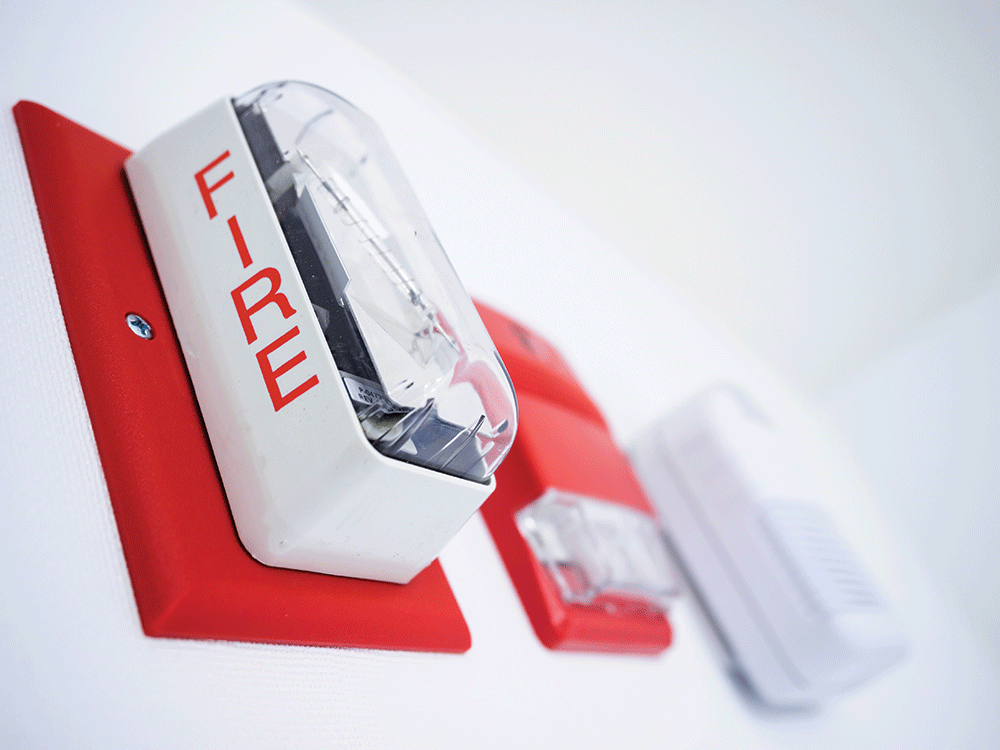
Article 760, Fire Alarm Systems, in the NEC covers the installation of wiring and equipment for fire alarm systems, including all circuits controlled and powered by the system. Examples of fire alarm circuits include initiating devices, notification appliances, waterflow devices, guard’s tour, and sprinkler supervisory circuits. Some examples of equipment that can be controlled by the fire alarm system — but not powered — include smoke ventilation, HVAC, magnetic doors, coiling doors, elevator shutdown and recall, damper controls, and emergency lighting control units. A fire alarm system is a system of components that usually includes a fire alarm control unit, a secondary power source, circuits or pathways, raceways, boxes, initiating devices, notification appliances, and building interfaces.
Section 760.1 explains that any circuit that is controlled by the fire alarm system falls under the scope of Article 760. Any building-controlled devices or life safety equipment that is only interfaced with the fire alarm systems shall fall under the scope of Article 725, Remote Signaling Circuits.
As covered in Section 760.24, there should be special attention given to the installation of all related conductors, boxes, equipment, and devices for fire alarm systems. Fire alarm circuits shall be installed in a neat and workmanlike manner. Cables and conductors shall be supported in a way to ensure that they will not be exposed to damage and supported by the building structure. Specifically, type CI cable (circuit integrity type) shall be supported at a distance not exceeding 610 mm (24 in.) and protected if installed within 2.1 m (7 ft) from the floor.
Fire alarm circuits shall be properly identified at all terminal and junction boxes. The key here is protecting the conductors from being disconnected or mistaken for other circuits leaving an impairment to the system.
Equipment used for fire alarm installations shall be listed for its purpose. Be aware of how the equipment, conductors, boxes, and devices are installed. Look for faulty or incorrect installations that may impair the system further down the line. Moisture can be one of the biggest enemies for fire alarm systems; ensure that you install a system that is ready to fight against any and all moisture. Any equipment installed in wet locations shall be marked for “use in wet locations.” All equipment that is subjected to damage shall be protected by a listed means.
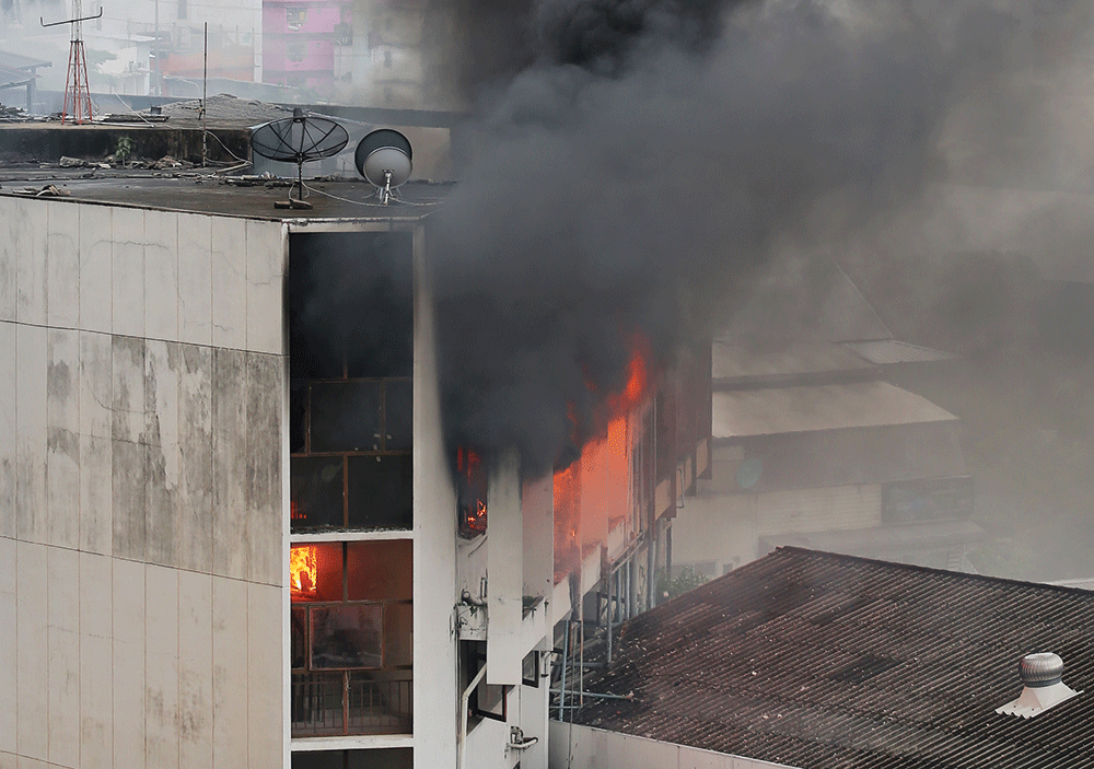
The 2019 National Fire Alarm and Signaling Code has created different pathway classifications to increase reliability for certain types of circuits used for fire alarm systems.
In Section 12.3, we see that pathways shall be designated as Class A, Class B, Class C, Class D, Class N, and Class X, depending on their performance. This gives designers, installers, and inspectors’ performance capability for circuits depending on how they want the pathway to perform. For example, take a Class A circuit that includes a redundant path. Operation continues past a single open, conditions that affect the operation annunciate a trouble signal, operation is maintained during a single ground fault, and that single ground fault will annunciate a trouble signal. A Class B circuit does not include a redundant path; operation stops at a single open. Class A circuits have better reliability than Class B circuits but may not always be necessary. These parameters allow the industry to step back and take a look at the big picture, “what type of pathway will maintain the integrity of the system.”
Pathway survivability is a standard of survivability levels during emergencies for occupancies that have partial relocation or evacuation, emergency communications systems, notification zones separated by less than 2-hour fire ratings, area of refuge, elevator emergency communications systems, and circuits that are intended to transmit off-premises signals. Those parameters are described in Chapter 24, section 24.3.14.
The levels of survivability are outlined in Chapter 12, Section 12.4. The four levels are:
- Level 0 does not require any provisions for pathway survivability.
- Level 1 shall consist of pathways in buildings that are fully protected by an automatic sprinkler system in accordance with NFPA 13 with any interconnecting conductors, cables, or other physically protected pathways protected by metal raceways or metal armored cables.
- Level 2 shall consist of one or more of the following: 2-hour fire-rated circuit integrity (CI) or fire-resistive cable, 2-hour fire-rated cable system (electrical circuit protective systems), 2-hour fire-rated enclosure or protected area, or performance alternatives approved by the authority having jurisdiction.
- Level 3 shall consist of pathways in buildings that are fully protected by an automatic sprinkler system per NFPA 13 and in one of the following: 2-hour fire-rated circuit integrity (CI) or fire-resistive cable, 2-hour fire-rated cable system (electrical circuit protective systems), 2-hour fire-rated enclosure or protected area, or performance alternatives approved by the authority having jurisdiction.
In conclusion, we must remember why fire and life safety systems exist — to protect the building and, most importantly, save lives! Take the extra steps when working with the systems to ensure that you do everything you can to maintain the integrity of the systems. Do your research, study the codes and standards, ask questions, and question everything regarding the systems’ integrity and functionality. Also, always lean on experts in the industry who have the needed experience to guide you towards a reliable, well-functioning system that is going to perform the functions that may ultimately save someone’s life.



Find Us on Socials