
This article informs specifying engineers, original equipment manufacturers, designers, and end users about the most important features in arc-flash relay technology so that they can select the best relay for their application.
Arc-Flash Mitigation Basics
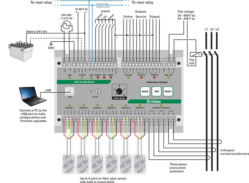
Arc-flash relays (see figure 1) are an important part of an arc-flash mitigation strategy. Arc-flash relays are compact. They can quickly detect a developing arc flash by sending a trip signal to the circuit breaker, which reduces the total clearing time and any subsequent damage. They do this by providing an output that directly activates an electrical system circuit breaker, which cuts off the current flow to the arcing fault.
Arc-flash relays help companies comply with the NEC, which, in certain cases, requires workers to adjust the circuit protection device to instantaneously trip when working inside an arc-flash boundary. The code says that workers do not need to take this extra step if an arc-flash relay is protecting the cabinet.
The installation of an arc-flash relay reduces the total clearing time and the amount of energy that is released through an arcing fault. The fastest arc-flash relays can detect a developing arc flash and send a trip signal to the breaker in less than 1 millisecond. The circuit breaker will open 35 to 50 milliseconds later [times will vary depending on the type of circuit breaker and how well it has been maintained]. Because an arc flash can draw a fraction of bolted-fault current, especially in its initial stages, circuit breakers alone should not be relied upon to distinguish between the arcing current and a typical inrush current.
With an arc-flash relay, there is less damage to equipment, as well as fewer and less severe injuries to nearby personnel. This damage is usually minor and limited to the fault point where the arc originated. It avoids the more widespread and severe damage that occurs during a full- blown arc flash.
The Most Important Features of an Arc-Flash Relay
The most important aspects of arc-flash relays are their
- reaction time,
- trip reliability,
- ease of installation,
- sensor flexibility,
- software,
- sensor design,
- avoidance of nuisance tripping, and
Reaction Time
The arcing current during the initial stage of an arc flash is too low to trip circuit breakers. This is because circuit breakers are sized to only tolerate temporary rises in currents that are caused by transients.
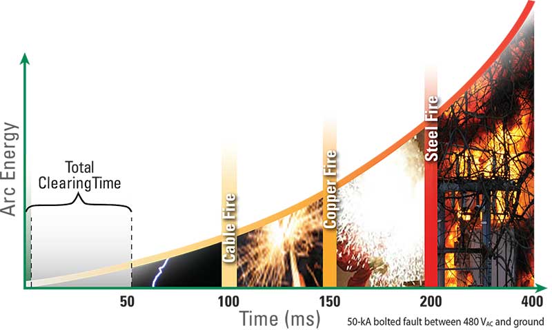
For example, when the current rises on a 50-kA bolted fault between 480 V ac and ground, the cable insulation will catch fire in about 50 milliseconds. Within 100 milliseconds, the copper conductor will begin to vaporize. In addition to the intense light, the arc flash will generate extreme heat and an explosive high-pressure wave.
Because light is the earliest detectable indication that an arc flash is occurring, most arc-flash relays use optical light sensors to detect a developing arc. The output of the light sensor is hard-wired to the arc-flash relay, which trips a circuit that interrupts the energy supply in the arc. The speed that this occurs, depends on the arc-flash relay’s design. The fastest arc-flash relay times range from about less than 1 millisecond to 9 milliseconds.
These reaction times are a function of the arc-flash relay’s light sensor input sampling scheme and how the trip output circuit is designed. Avoidance of nuisance is important to a relay’s sampling scheme. For example, Littelfuse PGR- 8800 Arc-flash Relay’s light sensor inputs (which can have up to six light sensor inputs per relay and up to 24 per system) are sampled every 125 microseconds (which is a sample frequency of 8 kHz).
The Littelfuse PGR-8800 detects an arc flash when its sensor captures a level of light intensity that is greater than the trip level. After the relay counts a sufficient number of consecutive samples that are above the trip level, it will activate the output.
As part of a sensor sampling scheme, a programmable time-delay filters the inputs. This establishes the number of samples that are needed to trip the relay and thereby filter out photo flashes, which can cause unintentional trips. Typically, a programmable time delay filter can be set between zero (instantaneous light detection) and one or two seconds for special application conditions.
After an arc-flash relay’s input time delay, it takes a certain amount of time for its electronic output to turn on. This is a function of the type of output relay used. Solid-state outputs (such as, insulated gate bipolar transistors (IGBTs) are much faster than electromechanical relays and can operate within 200 microseconds.
IGBTs are one of the fastest types of solid-state outputs in arc-flash relays. The PGR-8800 and AF0500 are built with these outputs and are therefore able to react within 200 microseconds from the detection of an arc-flash event.
The Littelfuse PGR-8800 and AF0500 arc-flash relays:
- Have a default delay of 500 microseconds,
- Require three consecutive samples that are above the trip threshold, and
- A 200-microsecond turn-on time on their IGBT output. The PGR-8800 and the AF0500’s 125-microsecond IGBT turn-on time and the sample interval corresponds to a minimum trip time (with no time delay filtering) of less than 0.5 milliseconds.
An overall sampling time is proportional to the number of sensors that the relay uses. The PGR-8800 relay uses a maximum of six sensors. Therefore, its reaction time specification is less than 1 millisecond.
Trip Reliability
Next to reaction time, reliable tripping is the most important characteristic of an arc-flash relay because it ensures the mitigation of an arcing fault. There are two aspects of trip reliability that are important: trip redundancy and system-health monitoring.
Redundant Tripping
Most arc-flash relays do not have a redundant tripping feature. However, an arc-flash relay without redundant tripping is like a car that has seat belts but not air bags. It is an unsafe approach to safety. It has both primary and secondary trip path logic. The primary path is controlled by the internal microprocessor and its embedded software and works by activating the coil of the primary trip relay.
The redundant path typically uses a discrete solid-state logic that does not go through the microprocessor. Any failure in the microprocessor will cause the unit to switch automatically to its redundant path, which activates a shunt-trip relay without delay when a sensor input is above the light detection threshold. A solid-state redundant path is not influenced by programmable settings such as time delay. Some relays provide an option for under voltage or shunt trips; the redundant path usually operates in shunt mode, so an under-voltage coil will trip immediately if the microprocessor fails.
Health Monitoring
People often say, “A chain is only as good as its weakest link.” Health monitoring ensures that the system is in good operating condition. From the sensors to the output of the arc-flash relay trip circuitry, the relay should monitor every applicable component within the system.
Most arc-flash relays have some degree of internal health monitoring, though these capabilities can vary between models. The Littelfuse PGR-8800 and AF0500 relays have built-in health monitoring throughout the entire device. The relay sends a signal to the light sensor and verifies that it is working. The sensor will then send a signal back to the relay. Fiber-optic sensors verify that the entire length of the cable is not pinched or broken.
Although some arc-flash relays indicate the sensor status on the face of the relay, the relay will not be visible to a worker in another location. No other arc-flash relay will provide on-sensor indication of the scanning or the health status of the system.
The AF0500, AF0100 and PGR-8800 relays are exceptions to this limitation. Their point sensors have an LED indicator that shows if the light detection is properly functioning. On-sensor health indication can be critical in preventing maintenance work on equipment where protection is inactive because the worker can immediately see that the sensor LED is off.
Blinking lights—a feature of the AF0500, AF0100 and PGR-8800—which indicate the health of a sensor, optimize health monitoring features because workers will immediately know if the installation was successful. If the sensor has detected a fault, then the blinking light will turn solid. This allows the user to quickly and efficiently identify where the fault is located.
Ease of Installation
The easiest-to-install arc-flash relays do not need PC configuration.
The Littelfuse AF0500, PGR8800 and AF100 arc-flash relays are plug and play devices—meaning that these relays are ready for use as soon as they are plugged in. They do not require set up and or PC configuration. (Although PC configuration for both the AF0500 and PGR-8800 is optional, it is only necessary for configuring certain advanced behaviors or multiple power sources.)
Sensor Flexibility
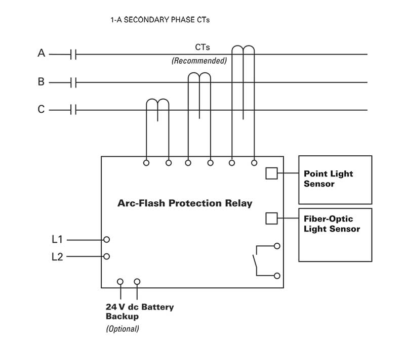
A relay’s input should accept point sensors as well as fiber-optic sensors. The AF0500, AF0100 and PGR-8800 arc-flash relays can flexibly mix point sensors and fiber optic sensors using the same inputs. The person installing these Littelfuse relays can modify the sensor configuration and adapt it if necessary. They can also be reconfigured for a different cabinet in the future.
The sensors in the Littelfuse relays have the flexibility of being switched out with another type of sensor at any time. This feature is uncommon to arc-flash relays; most relays have a predetermined type of sensor and can never be reconfigured. These relays are not flexible, which complicates their installation and increases cost.
Small electrical panels should only use arc-flash relays that are easy to install.
Beyond feeder switchgear cabinets, arc-flash protection can be extended to transformers, power converters, and motor control centers.
Software
A few arc-flash relays, including the PGR-8800 and the AF0500, have software with an event logging feature. This is useful for tracking trends in the system’s performance. It should record the specific sensor that started the fault, which will make troubleshooting easier. Both the PGR-8800 and AF0500 relays can log up to 1000 events, and the PGR-8800 also includes waveform capture. Waveform capture provides detailed data on the light and current intensity surrounding the time of a fault.
Relays are configured with data communication interfaces, which come in a variety of styles. USB interfaces simplify and shorten the relays setup to less than five minutes, even in complex scenarios that have multiple modules, current sensors and customized trip levels (See Figure 3). Events can be stored in a log file, which can also be accessed remotely via the USB interface to generate reports and graphs of historical data.
Power system analysis software companies use arc-flash relays in their component libraries. This allows users to perform a “what-if” analysis for a variety of relay configurations, circuit variables, and fault conditions.
Sensor Design
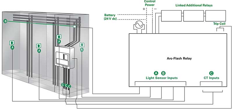
Most arc-flash relay installations have multiple fixed-point light sensors near the vertical and horizontal bus bars, which is where arcing faults are prone in feeder switchgear cabinets. Enough sensors should be installed to cover all accessible areas, even if the company policy is to only work on de-energized systems.
An arc fault should be visible to a minimum of two sensors in case a person blocks another sensor’s field of view. Light sensors may also be installed in other electrical cabinets and in panels that are subject to routine maintenance and repairs, such as those in motor control centers.
In addition to fixed-point sensor inputs, some arc-flash relay manufacturers supply sensors with fiber-optic strands, which have a 360-degree field of view for detecting light. This allows for a more flexible positioning of the light sensing locations because the fiber-optic strands can be looped throughout an enclosure or a panel, which will then cover challenging component layouts. Some arc-flash relay manufacturers supply fiber strands that range from 26 to 65 feet long or offer interconnection hardware for even longer lengths.
However, long “open” fiber strands (which are designed for light reception across the entire length of the strand) should be used with caution. Depending on the location of an arc flash relative to the far end of such a strand, the light that arrives at the end of the detector may not be bright enough to cause a relay trip. This is due to attenuation along the length of the fiber. Some manufacturers avoid this problem by using interconnecting hardware with hard-wired outputs from the interconnection and detector points back to the arc-flash relay. For example, the Littelfuse PGR-8800 allows up to six light sensor inputs per relay, and up to four relays can be interconnected to act as a single unit. This means up to 24 light sensor inputs can be used to monitor an electrical equipment configuration.
Our sensors are pre-terminated and pre-calibrated in a factory instead of being sliced sleeved and polished in a field environment. This means that we have eliminated the human element of error that can result in nuisance tripping.
Avoidance of Nuisance Tripping
Most arc-flash relays use light sensors with fixed detection thresholds that are set between 3,000 to 10,000 lux light intensity.
With this light sensor setting, the relay will not nuisance trip on everyday bright lights such as the light from a LED flashlight or the flash from a cellphone camera (See Table 1).

Nevertheless, it can be useful to raise the setpoint to minimize nuisance tripping. For example, opening a switchgear cabinet to direct sunlight, a professional camera flash, or a worker welding nearby can set off the arc-flash relay inadvertently, which causes costly downtime.
Some arc-flash relays also use a phase-current sensing scheme to avoid nuisance tripping. A phase-current sensing scheme uses three current transformers to measure the three phrase currents in the system.
If the microprocessor logic receives an input from a light sensor, it checks for a rapidly rising input from the current transformers. If present, it will send an output signal to the disconnect device.
However, using rms-current sensing is not the best way to implement this feature. Edge detection is a better approach. Relays that utilize edge detection, such as the PGR-8800 relay, use instantaneous current values to detect a rapidly rising current. This will indicate an arcing fault and avoid unnecessary delays in the relay’s trip time should an arc flash occur.
With this method, the microprocessor looks for the numerically largest of the three phase currents at any given sample. The largest phase current is then compared to the threshold programmed by the user.
In addition, delays are available in the overcurrent-trip configuration, which says how long the maximum value must stay above the limit for the unit to trip the output.
Current transformer current verification will not affect the relay’s reaction time. The PGR-8800 relay, for example, has a total trip time of less than 1 millisecond, which is subject to the user-selectable time-delay setting.
Scalability
Several arc-flash relay designs allow the interconnection of multiple units. This configuration allows a downstream arc flash to trip the upstream circuit breaker. This can be very useful where the upstream substation is feeding downstream motor control centers (MCCs). It is common to work on live MCCs, which drastically increases the chance of an arc-flash incident.
However, the MCC may not have a main circuit breaker with a shunt trip, which would otherwise allow it to be tripped remotely. That means there is no method to remove power if an arc-flash event is detected. An arc-flash relay installed in the MCC and tell the upstream relay or a networked relay to trip the main circuit breaker feeding the MCC.
The AF0500 and the PGR-8800 relays have upstream breaker trip functionality. If the local circuit breaker fails to open, then another command will be sent (after a short delay) to the upstream breaker. The AF0500 relay has two IGBT outputs, which allows for communication to both upstream and downstream circuit breakers.
Zone Tripping
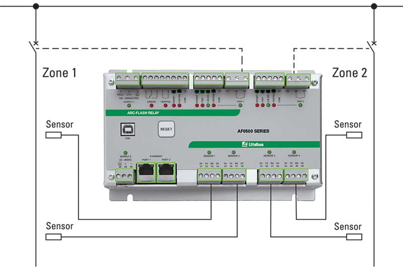
The AF0500 can be used as backup for a zone-select interlock system (see Figure 5). This creates an additional level of redundancy.
Some relays, such as the PGR-8800 relay, accomplish zone tripping by networking multiple relays together. The AF0500 relay, in contrast, has built-in zone trip capability. One AF0500 relay can monitor two separate zones by using separate sensors. The relay can trip different breakers for each zone, trip the same breaker, or trip a local breaker and upstream breaker for a single zone.
Zone tripping minimizes outages. For example, an arc-flash event may only trip the affected portion of a cabinet (rather than shut down the entire cabinet when zone tripping is used). Zone tripping can also open a circuit breaker on the incoming feeder while simultaneously opening a tie breaker so that the power is not routed from a second feeder.
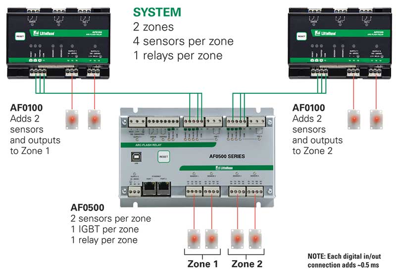
Build a Customized Arc-Flash System Without Complex Programming or Configuration
Connect the AF0100 and AF0500 together to design a right-sized protection system. Use the innovative digital input and output terminals to add sensors or zones (see figure 6).
Retrofitting
Nobody enjoys a complicated configuration process or to have to make changes to existing layouts when installing new relays into existing switchgear. To avoid this, use relays such as the Littelfuse AF0500 or the AF0100 that have flexible sensor configuration, which makes the relay suitable for any application, no matter how elaborate the system is. Both relays have a built-in USB PC interface and digital inputs and outputs that eliminate a need to install configuration software onto a PC.
Conclusion
Arc-flash relays are vital to mitigating an arc flash. Every system is not the same, nor are arc-flash relays. To effectively protect against an arc flash, a relay must be fit for the system. The most important features of an arc-flash relay are:
- reaction time,
- trip reliability,
- ease of installation,
- sensor flexibility,
- software,
- sensor design,
- avoidance of nuisance tripping, and
Additional Arc-Flash Resources
Refer to our arc flash technical FAQ for a comprehensive list of questions and answers related to arc flash and arc-flash relays. The Littelfuse arc-flash web page, Littelfuse.com/ArcFlash, also provides a comprehensive collection of resources about arc flash, such as:
- An arc-flash relay brochure
- an arc-flash energy reduction calculator
- a case study on how the Littelfuse PGR-8800 arc-flash relay saved a plant from almost $1 million in damages and downtime.
Technical information and application data for Littelfuse protection relays, fuses, and other circuit protection and safety products is available on www.littelfuse.com/protectionrelays. For questions, contact our Technical Support Group at (800) 832-3873 or relays@littelfuse.com.