The IAEI/UL Technical Advisory Panel (TAP) was established in 1997 to address several technical issues that require research. One of the first actions of the TAP was to assign a Task Group to review the grounding provided by metal raceway systems described in NEC Section 250-118 [previously Section 250-91(b)], and focus on the use of the armor of Type AC cable as an effective equipment grounding path.
Type AC cable is described in Article 333 of the NEC. It consists of a fabricated assembly of insulated conductors in a flexible metallic (armored) enclosure. Type AC cable has a long history of use, as evidenced by the Standard for Armored Cable, UL 4, which was first published in 1917. Section 250-118(9) of the NEC permits the armor of Type AC cable to be used as an equipment grounding conductor. However, Section 250-2(d) also requires a fault current path to be capable of safely carrying the maximum fault likely to be imposed on it, and have sufficiently low impedance to facilitate the operation of overcurrent devices under fault conditions. To demonstrate the ability by which Type AC cable complies with the requirements of Section 250-2(d), the Task Group developed a test plan that involved ground-fault current testing with Type AC cable installed in insulated walls.
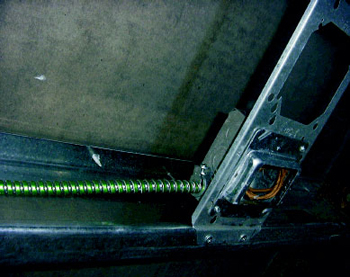
Photo 1
Ground-Fault Current Tests
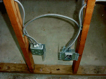
The ground-fault current test plan developed by the Task Group utilized a laboratory scenario consisting of a wall 20 feet long and 4 feet high with 2×6 inch studs on 24-inch centers. Two conductor, No. 12 AWG, 90°C Listed Type ACTHH cable was installed through holes in studs for the 20 ft length of wall. Separate tests were conducted with both steel and aluminum armor AC cable. Two junction boxes, 2×3 inch gangable, with fittings, were installed within the wall as shown in figure 1. Different types of 3/8-inch diameter fittings, Listed for use with AC cable were used. The fittings consisted of the (1) set-screw, (2) clamp connector, and (3) squeeze connector types. The fitting locknuts were hand-tightened plus 1/4 turn. The wall was fully insulated using R-25 fiberglass insulation, 8-3/4 inch thick compressed to 5-1/2 inch. The insulated wall was closed on both faces with 3/16 inch thick wood paneling. At the end of the wall farthest from the supply, the current-carrying conductor of the AC cable was connected directly to a metal outlet box producing a ground return path through the cable armor, fittings, and metal boxes back to the current supply source (see figure 1).
Ground fault tests with current flowing through the armor on the Type AC cable were conducted at the current and time durations noted in table 1 (below).
| Current (Amps) | Time (Duration) |
| 16 | 8 hr. |
| 20 | 3 hr. |
| 27 | 1 hr. |
| 40 | 120 sec. |
| 50 | 20 sec. |
| 100 | 2 sec. |
The selected durations for the 100- and 50-amp tests were based on the maximum measured tripping times of several typical 20-amp residential circuit breakers currently on the market. The selected durations for the 40- and 27-amp tests were based on the maximum permitted tripping times from the Standard for Circuit Breakers, UL 489. The selected durations for the 20- and 16-amp tests were based on theNECdescriptions of continuous and non-continuous circuit loading respectively.
During each test, temperatures were measured at points along the Type AC cable armor and on the cable fittings. The maximum temperature rises recorded on the armor and fittings were noted in table 2.
Table 2
For research purposes, the test at 27 amps with steel armor was repeated with a 20-amp residential circuit breaker in the circuit. The breaker tripped after approximately 5 minutes of operation. The maximum temperature rise on the cable armor was 37°C as compared with the 161°C for the one-hour test duration.
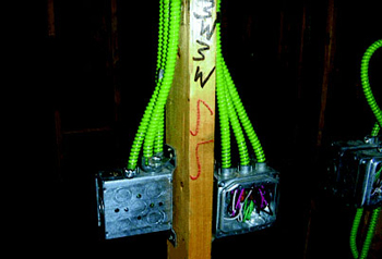
Photo 3
The Standard for Armored Cable, UL 4 requires an uninsulated bonding strip of aluminum not smaller than 16 AWG throughout the entire length of the cable. Voltage drop measurements made before and after the ground-fault current tests indicated that the bonding strip was not damaged by the fault currents.
The Standard for Armored Cable, UL 4, requires the ohmic resistance of the finished armor, including the bonding strip, to be not greater than 0.64 ohms per 100 feet for cable with No. 12 AWG conductors. The measured 100-foot resistance of the armor and bonding strip for the AC cable used in these tests was 0.57 ohms for the steel armor and 0.36 ohms for the aluminum armor.
From the measurements and test data obtained with steel armored Type AC cable, a calculation was made to determine the circuit length needed, assuming ten boxes with fittings in the circuit, to produce a 20-amp ground fault at 120 volts. The calculated length of No.12 AWG Type AC cable was 725 feet. The calculations used to obtain this length are shown in table 3 (below).
Circuit Characteristics of the Test Set-Up
Resistance Measurements and Calculations
Calculations of Circuit Length
|
Summary
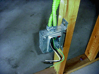
Photo 4
The results of the ground-fault current tests conducted at 40, 50, and 100 amps showed minimal temperature rises on the cable armor and fittings. This was based on the overcurrent device opening times being fast enough to prevent overheating of the cable assembly even under these abnormal current conditions. The test conducted at 27 amps for 1 hour without overcurrent protection produced the highest temperature rise of 161°C on the steel armor. However, repeating the 27-amp ground-fault current test with a 20-amp residential circuit breaker protecting the circuit produced a maximum temperature rise on the test assembly that was significantly lower (37°C), since the circuit breaker opened in approximately five minutes.
Following the ground-fault current test at 27 amps for 1 hour without overcurrent protection, the tests conducted at 16 amps for 8 hours and 20 amps for 3 hours produced the highest temperature rises, up to 105°C for the 20-amp test. Circuit length calculations show that a minimum of 725 feet of No. 12 AWG Type AC cable would be needed to produce a 20-amp ground fault, an extremely long circuit given typical building sizes and voltage drop considerations. It should be noted that NEC Section 210-19(a), FPN No. 4, recommends a maximum voltage drop of 5 percent. For a 120-V, 20A branch-circuit with No. 12 AWG copper wire, this would necessitate a circuit length of not greater than 75 ft.
The results of this research project with No. 12 AWG Type AC cable demonstrate the ability of Type AC cable construction to safely carry the maximum fault likely to be imposed on the cable, and have sufficiently low impedance to facilitate the operation of overcurrent devices under fault conditions.