Electrical hazards, such as arc flash, can be extremely damaging to equipment and, more importantly, to people. An alarming number of electrically related accidents occur each year, often resulting in serious third degree burns or death. Luckily there have been recent significant advances in the electrical industry surrounding electrical hazards, particularly arc flash. The following discussion will detail the dangers and nuances surrounding arc-flash hazards and overview recent advancements in the electrical industry to minimize their occurrences.
The Cause:
Working on or near live electrical equipment
Before we discuss arc-flash incidents themselves, we need to understand the cause. The most alarming fact is that arc-flash incidents occur when electrical systems are energized. The basic “law of the land”1 is to de-energize electrical equipment, or place it in an electrically safe working condition, prior to servicing or maintenance, except for two demonstrable reasons:
1. de-energizing introduces additional or increased hazards (such as cutting ventilation to a hazardous location), or
2. infeasible due to equipment design or operational limitations (such as when voltage testing is required for diagnostics).
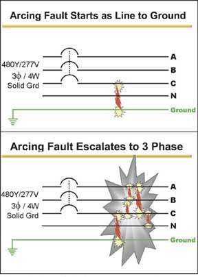
Figure 1. One major characteristic surrounding arcing faults is progression of the fault to other energized parts of the system caused by the buildup of ionized matter in the arc
Even though ignoring these regulations and practices is a violation of federal law,2 the unfortunate fact is that work is often conducted “hot,” or on energized equipment, inviting an electrical injury to occur. Working on live electrical equipment is a serious risk. All it takes is a co-worker grabbing your attention for a split second, resulting in the slip of a screwdriver or loose hardware falling and contacting a live part, and within the time it takes to blink an eye a serious arc-flash injury or death can occur. Some examples of factors which could promote live electrical work include1.
- pressure to keep production running,
- trying to save time on a job because it is the end of a shift or of
- taking electricity for granted because we have been doing it for so many years that we know what we are doing and nothing can go wrong.
Arcing Faults
Arc-flash incidents are caused by arcing faults. Faults on an electrical system cause current to travel out of its normal path. There are primarily two types of faults: bolted faults and arcing faults. Bolted faults are characterized by a solidly connected fault path causing high levels of current to flow through this solid connection. This type of fault is commonly used when testing electrical equipment for short-circuit current ratings and overcurrent protective devices for interrupting ratings. Arcing faults differ in the fact that the current actually flows through ionized air causing an arc. The major difference between these two types of faults is that the energy in a bolted fault condition is dissipated in the faulted equipment while an arcing fault releases energy out into the surrounding environment.
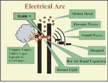
Figure 2. The arc model shown in figure 2 shows the physical aspects of an electrical arc.
Unlike bolted faults, the predictability of an arcing fault and the energy released vary. This is due to the arcing fault’s dependence on many variables. Some of the variables that affect the outcome include:
- available bolted short-circuit current on the system
- the time the fault is permitted to flow (speed of the overcurrent protective device)
- arc gap spacing
- size of the enclosure or no enclosure
- power factor of fault
- system voltage
- whether an arcing fault can sustain itself
- type of system grounding and bonding scheme
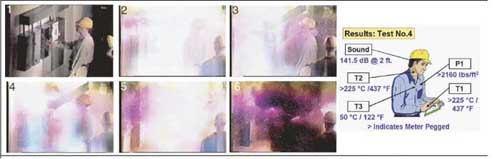
Figure 3. Test 4 and Test 3 were identical except for the overcurrent protective device protecting the circuit
One major characteristic surrounding arcing faults is progression of the fault to other energized parts of the system caused by the buildup of ionized matter in the arc (see figure 1). For example, a line-to-ground arcing fault can quickly escalate into a 3-phase arcing fault as the ionized gas produced envelops the other energized parts of the equipment. This causes other phases of the electrical system to become involved in the arcing fault, thus increasing the amount of electrical energy feeding into the fault; and increases the extent of the fault and incident. This characteristic is a major driver behind arc-flash incidents.
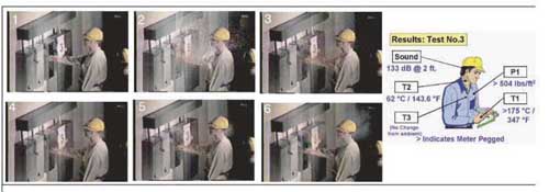
Figure 4. Test 4 and Test 3 were identical except for the overcurrent protective device protecting the circuit
To understand this principle of fault progression, look at the physics surrounding an electrical arc. The arc model shown in figure 2 shows the physical aspects of an electrical arc. The catalyst is the intense heat contained within an electrical arc. Temperatures can reach 35,000°F, roughly four times the temperature of the surface of the sun. This intense heat can rapidly melt or even vaporize copper, which has a melting point of approximately 1900°F, much lower than the 35,000°F contained within the electrical arc. This intense heat often results in copper vapor and molten metal. When copper changes state from solid to vapor, it expands to 67,000 times its original volume. This would be similar to a one square centimeter piece of copper changing to the size of a 38 cubic foot cooler in a split second. In addition, this intense heating causes high intensity pressure and sound waves to develop from the super heating of the surrounding air. These intense pressures can:
- carry the intense heat from the arc out into the surroundings,
- knock workers off ladders or throw them across a room,
- blow apart components and explode shrapnel into the surroundings at high velocity (which can be in excess of 700 miles per hour).
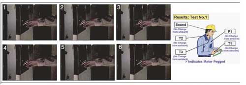
Figure 5. In Test 1 (see figure 5), the arcing fault is initiated on the load side of the branch-circuit overcurrent protective devices, which are 30-ampere, current-devices
Alarmingly all this can happen in only a small fraction of a second, and injuries can occur to persons within proximity of the arcing fault even if they are not working directly on the equipment. Yes, this can and does affect the electrical inspector. It is not uncommon for a piece of hardware, such as a nut or washer, to fall into energized parts when a door is opened or closed, or when the handle is operated on a switch or circuit breaker.
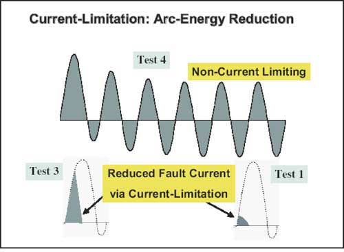
Figure 6. In addition, sound intensity dropped from 141.5 dB (intensity of tornado/hurricane siren) to 133 dB (intensity of shotgun being fired). This is due to the reduction in time and energy in Test 3 as compared to Test 4
Arcing faults release energy into the area surrounding the fault. Unfortunately, the surroundings include the space where the electrical worker and bystanders are often positioned. Serious accidents are occurring at an alarming rate on systems of 600 V or less, in part because of the high fault currents that are possible. But also, designers, management and workers mistakenly tend not to take the necessary precautions that they take when designing or working on medium and high voltage systems. In order to relate the level of danger involved, we must investigate some important thresholds for the human body. One important danger associated with arc flash is burns resulting from the high levels of heat. Burns are often categorized as to the extent of the burn. For reference, a second-degree burn threshold, or a “just curable burn threshold,” is skin temperature raised to 175°F for 0.1 second, while a third-degree burn threshold or “incurable burn threshold” would result from skin temperature raised to 200°F for 0.1 second. Another important danger would be injury resulting from the intense pressure associated with an arc-flash incident. Two important thresholds relating to pressure for the human body include:
– Eardrums 720 lbs/ft2
– Lung Damage 1728 2160 lbs/ft2
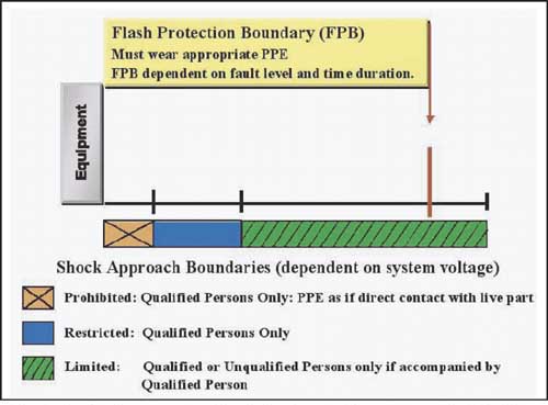
Figure 7. NFPA 70E requires a hazard/risk analysis to be conducted before working on electrical equipment. The core of this analysis surrounds determination of arc flash and shock boundaries
The eardrums represent the lower level threshold for damage due to their direct exposure to pressure waves, while lung damage is a good upper threshold due to the protection provided by the rib cage.
Extensive tests and analyses by industry have shown that the energy released during an arcing fault is related to two characteristics:
1. The duration of the arcing fault (time)
2. The amount of fault current or energy feeding the fault
Selection and performance of overcurrent protective devices play a significant role in electrical safety. Overcurrent protective devices contribute to 1) control the duration of the fault and 2) sometimes limit the amount of arcing fault current depending on the type of overcurrent protective device selected. Therefore devices that can react quickly to an arcing fault and reduce the amount of fault current available, aid in reducing the energy released. The lower the energy released the better for both worker safety and equipment protection.
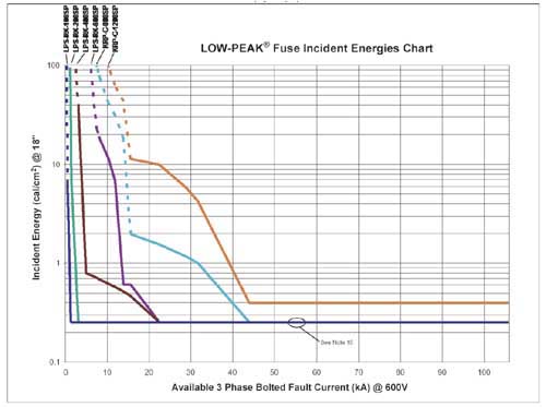
Figure 8. Simply take the available bolted short-circuit current at the panel, and apply it to the horizontal axis of the chart in (figure 8). Then read off the incident energy level for that level of fault current.
To support this philosophy, testing has been conducted and has proven that the arcing fault current magnitude and time duration are the most critical variables in determining the energy released. One such series of tests was conducted by an ad hoc electrical safety working group within the IEEE Petroleum and Chemical Industry Committee.3 The data collected, including the photos and measurements from actual arcing fault tests (see figures 3, 4, and 5), support this philosophy.
An important section of the testing is summarized here. Three critical tests will be highlighted as an example of the results obtained.
Test 4, Test 3 and Test 1: General
All three of these tests were conducted on the same electrical circuit set-up with an available bolted three-phase, short-circuit current of 22,600 symmetrical rms amperes at 480 V. In each case, an arcing fault was initiated in a size 1 combination motor controller enclosure with the door open, as if an electrician were working on the unit “”live”” or before it was placed in a safe work condition.
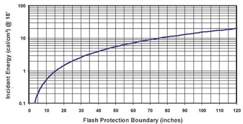
Figure 9. The next step in this simplified flash hazard analysis is to determine the Flash Protection Boundary (FPB). After obtaining a value for incident energy exposure, the chart in (figure 9) can be consulted to determine the FPB.
Test 4 and Test 3 were identical except for the overcurrent protective device protecting the circuit (see figures 3 and 4). In Test 4, a 640-ampere noncurrent-limiting device with a short-time delay protected the circuit; the circuit was cleared in 6 cycles. In Test 3, 601-ampere, current-limiting fuses protected the circuit; they opened the fault current in less than 1/2 cycle and limited the current. The arcing fault was initiated on the line side of the motor branch-circuit device in both Test 4 and Test 3. This means the fault is on the feeder circuit but within the controller enclosure.
In Test 1 (see figure 5), the arcing fault is initiated on the load side of the branch-circuit overcurrent protective devices, which are 30-ampere, current-devices. These devices limited this fault current to a much lower amount and cleared the circuit in approximately 1/4 cycle or less.
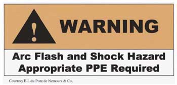
Figure 10. This new requirement is intended to reduce the occurrence of serious injury or death to workers due to arcing faults. The warning label should provide a reminder that a serious hazard exists and increase awareness of arc-flash hazards. Section
By observation of the results, both time and let-through current play a key role in the level of the arc-flash incident. For example, comparing the results of Tests 3 and 4, the measurements obtained in Test 3 were dramatically lower than those obtained in Test 4. The pressure level dropped from well above 2160 lbs/ft2, which would result in lung damage, to 504 lbs/ft2, which is below the threshold for eardrum rupture. Temperatures on the face dropped from well over 437°F, a severe third-degree burn, to 143°F, below the second-degree burn threshold. In addition, sound intensity dropped from 141.5 dB (intensity of tornado/hurricane siren) to 133 dB (intensity of shotgun being fired). This is due to the reduction in time and energy in Test 3 as compared to Test 4 (see figure 6).
Since arcing fault current levels can vary greatly, it is important to note that lower level arcing fault currents can sometimes be more dangerous than high level. This is related to the opening time of the overcurrent protective device. Arcing fault currents can be lower than the instantaneous trip threshold of a circuit breaker or current-limiting range of a current-limiting fuse, resulting in longer operating times.
As a result of this testing and the principles of arcing faults discussed, two important observations can be noted:
1. Tremendous amounts of energy can be released in a very small amount of time.
2. Overcurrent devices play a key role in extent of the incident.
NFPA 70E
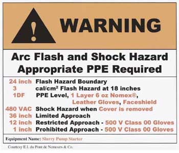
Figure 11. In light of the hazard/risk analysis mandated by NFPA 70E, it is suggested that the party responsible for the label include more information on the specific parameters of the hazard. In this way the qualified worker and his/her management can m
In light of this information and the number of injuries and deaths occurring, significant advances in the field of arc flash have occurred. In recent years significant knowledge has been gained through testing and analysis concerning arc-flash hazards and how to contend with this type of hazard. The most significant is the development of NFPA 70E–2000,4 Standard for Electrical Safety Requirements for Employee Workplace, the foremost consensus standard on electrical safety. NFPA 70E has developed requirements to reduce the risk of injury to workers due to shock and arc-flash hazards.
Why is there an NFPA 70E? In 1976 a new electrical standards development committee was formed to assist the Occupational Safety and Health Administration (OSHA) in preparing electrical safety standards. There were a number of reasons for development of an electrical safety standard such as:
1. The NEC is an installation standard, while OSHA also addresses employee safety in the workplace.
2. Not all sections in the NEC relate to worker safety and these are, therefore, of little value to OSHA’s focus and needs.
3. Many safety-related work and maintenance practices are not covered, or not adequately covered, in the NEC.
4. A national consensus standard on electrical safety for workers did not exist, but was needed—an easy-to-understand document that addresses worker electrical safety.
The result was the creation of NFPA 70E. The first edition was published in 1979. The current NFPA 70E–2000 consists of four parts:
Part I Installation Safety Requirements
Part II Safety-Related Work Practices
Part III Safety-Related Maintenance Requirements
Part IV Safety Requirements for Special Equipment
NFPA 70E requires a hazard/risk analysis to be conducted before working on electrical equipment. The core of this analysis surrounds determination of arc flash and shock boundaries (see figure 7).
Shock Boundary
Three shock approach boundaries are required to be observed in NFPA 70E–2000 Part II Table 2-1.3.4. Shock approach boundaries are dependent upon the system voltage. The significance of these boundaries for workers and their actions while within the boundaries can be found in NFPA 70E.
Flash Hazard Analysis
For arc flash, NFPA 70E requires a flash hazard analysis to be performed. The flash hazard analysis should determine the flash protection boundary (FPB) and level of personal protective equipment (PPE) that the worker must wear. The FPB provides a distance, from energized parts, representing the boundary between “just curable” and “incurable” burns. Work within this boundary requires the use of appropriate PPE. Appropriate PPE is determined by the available incident energy. The incident energy is a measure of thermal energy at a specific distance from an arc fault; the unit of measure is typically in calories per centimeter squared (cal/cm2). There are various types of PPE with distinct levels of thermal protection capabilities termed “Arc Thermal Performance Exposure Values” (ATPV) rated in cal/cm2. 5 Both the FPB and PPE levels are dependent on the available fault current and the overcurrent protective device, its clearing time, and if it is current-limiting.
Various Resources for Conducting Arc-flash Analysis
1. Calculations using NFPA 70E Formulas:
The following are the formulas in NFPA 70E–2000 for calculating the flash protection boundary and incident energy. It is significant to note that the flash protection boundary is dependent upon the available bolted short-circuit current (incorporated in MVAbf) (or the let-through current if the overcurrent protective device is current-limiting) and the opening time of the overcurrent protective device (t).
Flash Protection Boundary Calculation
Dc= (2.65 x MVAbfx t)1/2
where: Dc= distance in feet for a “”just curable”” burn
Df= distance in feet for an “”incurable burn””*
MVAbf= bolted three-phase MVA at point of short-circuit
= 1.73 X VOLTAGE L-L X AVAILABLE SHORT-CIRCUIT CURRENT X l0-6
t = time of exposure in seconds
Incident Energy Calculation [20″” cubic box]
EMB= 1038.7DB-1.4738tA[0.0093F2– .3453F+5.9675] cal/cm2
where: EMB= Incident Energy (cal/cm2)
DB= Distance, (in.) [for Distances = 18 inches]
tA= Arc Duration, (sec.)
F = Bolted Fault Short-Circuit Current
kA [16 kA to 50 kA]
2. NFPA 70E Tables and default FPB
Another method from NFPA 70E is the use of default 4′ flash protection boundary called out in NFPA 70E and PPE selection (using two tables: a. hazard risk category by tasks table, and b. PPE and tools for each hazard risk category table).6
3. IEEE 1584, IEEE Guide for Calculating Arc-Flash Hazard Calculations
The development of IEEE 1584 provides the electrical industry with an “industry” method of calculation. The standard covers arc-flash calculations for various overcurrent protective devices and includes an arc-flash calculator software program. For further information on this standard visithttp://standards.ieee.org
• Simple Graphical Arc-flash Analysis based upon IEEE 1584
The following is a simple method when using certain fuses; this method is based on actual arc-flash testing and subsequent current-limiting fuse performance data. Using this simple method, the first thing that must be done is to determine the incident energy exposure. Simply take the available 3Ø bolted short-circuit current at the panel, and apply it to the horizontal axis of the chart in (figure 8). Then read off the incident energy level for that level of fault current.
The next step in this simplified flash hazard analysis is to determine the Flash Protection Boundary (FPB). After obtaining a value for incident energy exposure, the chart in (figure 9) can be consulted to determine the FPB.
The last step in the flash hazard analysis is to determine the appropriate PPE for the task. To select the proper PPE, utilize the incident energy exposure values and the requirements from NFPA 70E. NFPA 70E has requirements for PPE that are based upon the incident energy exposures.
•Internet and Software Driven Arc-flash Calculators
Internet based or software driven calculators are becoming extremely popular. The benefit of these calculators is that they can simplify the process of conducting a flash hazard analysis. The easier the process is, the more likely that the process will be used. Examples of these arc-flash calculators can be seen atwww.bussmann.com/apen/arcflash/ 7 or athttp://standards.ieee.org
New NEC 110.16 Arc-Flash Label Requirement
This new requirement is intended to reduce the occurrence of serious injury or death to workers due to arcing faults. The warning label should provide a reminder that a serious hazard exists and increase awareness of arc-flash hazards. Section 110.16 only requires that this label state the existence of an arc-flash hazard (see figure 10).
In light of the hazard/risk analysis mandated by NFPA 70E, it is suggested that the party responsible for the label include more information on the specific parameters of the hazard. In this way the qualified worker and his/her management can more readily assess the risk and better insure proper work practices, PPE and tools (see figure 11).
Summary
Numerous injuries and deaths are caused each year by arc-flash incidents. Arcing faults result in numerous dangers due to the extremely intense high-level heat generated. The electrical industry is continuously working to advance the level of knowledge and understanding of arc-flash incidents. As covered earlier, the development of NFPA 70E provided a national work practice standard. This, along with OSHA law, is an effort to decrease the number of injuries that occur as a result of an electrical incident. Some recent advances have caused forward movement in safety and increased knowledge and understanding in this area. The majority of this work and effort surrounds dealing with work on or near live electrical equipment. Placing electrical equipment in a “safe working condition” highly reduces or even eliminates the likelihood that an arc-flash incident will or can occur and is required by federal law. Arcing faults are not selective. They can injure or kill anyone within their vicinity, not just the person working on the equipment. Oftentimes this includes electrical inspectors. Equipment must be de-energized for inspection (if the doors are open or the covers are off). If it is more dangerous to turn it off, wear adequate PPE for the distance from exposed, energized parts. Safe work practices are the key to the reduction in electrically related injuries; however, safe work practices work only when they are implemented. Implementing the practices and procedures available today will enhance worker safety and is critical to reduce the number of electrically related accidents that occur.