/01/In our top-to-bottom perspective of a photovoltaic (PV) system, we are still on the dc circuits from the PV array and are approaching the inverter. There are always a few details that get overlooked in designing, installing and inspecting these systems.
The Conductors
We have noted previously that single-conductor, exposed cables (type USE-2 or the new PV cable/PV wire) will be used for the module interconnecting cables. Both of these cable types will generally be available only in basic black. And as 200.6(A)(2) notes, this black cable, even when smaller than 4 AWG, may be marked white as a grounded conductor at the time of installation.
Normally the exposed single-conductor cables are transitioned to a conduit wiring method when the circuits leave the PV array. Conductors in conduit, while they could be USE-2/RHW-2 (for flame and smoke retardant) or PV wire, are typically THHN/THWN-2 because they are less costly and the -2 rating is needed for the outdoor, wet environment and the high temperatures of conduit in sunlight [310.15(B)(2)]. Unfortunately, 14–10 AWG conductors with THHN/THWN-2 insulation are not widely available due to low demand. (I’ll get e-mails telling me differently if I am misinformed). Of course THHN/THWN is available, but it doesn’t have a wet, 90°C rating. I expect that demand will increase for the small-conductor THHN/THWN-2 cables as inspectors start applying 310.15(B)(2) to roof top HVAC installations. Due to the limited availability of 14–10 AWG THHN/THWN-2, I tend to support the use of USE-2/RHW-2 in the conduits with a white marking although theCodedoes not clearly state that it can be used with markings in that location. XHHW-2 would also be a suitable alternative.
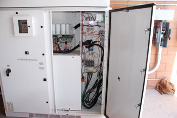
Photo 2. Xantrex 100kW Inverter
Although most PV arrays installed in the recent past have had the dc negative conductor grounded (and colored white), new arrays may have the dc positive conductor grounded and colored white. Of course, there are no designated color codes for the ungrounded conductor, but common sense would indicate that on a negatively grounded array with the negative conductor colored white, the positive, ungrounded conductor would be most clearly marked and understandable if it were colored red. However, many installations use a black positive conductor and that is still acceptable under theCode. In the positively grounded systems where the positive grounded conductor is colored white, the ungrounded negative conductor would be most clearly understood if it were black.
Now, and in increasing numbers in the next few years, the use of transformerless inverters will dictate the use of ungrounded PV arrays (690.35) and then we can go to a “red is positive” and “black is negative” color coding since there will be no grounded conductor.
Oh yes. We should not ignore the newest bipolar PV arrays and bipolar inverters. In these systems, we will have red, positive conductors, black, negative conductors, and white, grounded conductors.
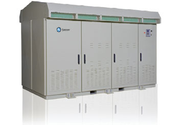
Photo 3. SATCON 1 MegWatt Inverter
As before, the grounded conductor in a PV dc disconnect should never be switched, although bolted, isolated, terminal-block connections are acceptable.
Wiring Methods, Continued
All circuits in a PV system, as in other electrical systems, must be wired using a Chapter 3 or 690.31 method that is suitable for the application and the environment. However, there are frequently questions about the circuits between the dc PV disconnect and the inverter. As far as theNECis concerned, if these circuits are in protected environments, they could be wired with type NM cable. Of course, local codes may dictate other requirements such as the need for using raceways inside commercial structures for all electrical wiring.
The Inverter
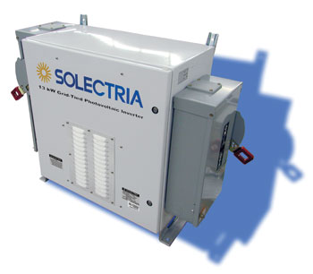
Photo 4. Solectria 13kW Inverter with external disconnects
Some inverters have only a single set of dc input terminals. With these designs, an external dc PV disconnect must be installed. Even if the inverter has more than one set of input terminals for parallel separate strings (source circuits) of modules, external dc PV disconnects must be used on each input. (See photo 4).
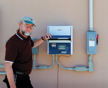
Photo 5. Inverter with internal disconnects as part of the inverter
Other inverters have internal dc disconnects or disconnect housings that attach to the main inverter section containing the electronics package. The method used to mount the internal disconnects, the ease and accessibility of the disconnects, and the manner in which they are separated from the inverter proper vary from brand to brand and from product to product. The installer and the AHJ must reach a mutual conclusion on the suitability of these disconnects for meeting the various disconnect requirements in theCode.
Since the inverters are listed with the disconnects, it can be presumed that the disconnects are properly rated for the dc load break operation. If the inverter is installed in a location that meets the 690.14 requirements for the main PV dc disconnect, then it would appear that the internal disconnect would meet this requirement.
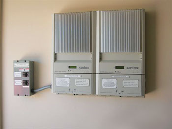
Photo 6. Inverter with internal disconnects that can be separated from inverter
Meeting the requirement for maintenance disconnects (690.15) will require additional considerations. If the inverter were to require factory service, can the energized PV source or output circuits be disconnected from the inverter safely when there is no external disconnect? If a disconnect housing is attached to the inverter and that housing does not have to be removed to service the inverter, then some degree of safety is assured. However, if the energized conductors must be disconnected from internal switches and pulled through small conduit knockouts, the situation must be examined carefully. Will qualified people who know how to disable the array be doing the removal? Or will the unqualified person try to pull energized conductors through the knockouts? (See photos 5 and 6).
DC Input Fusing
Some models of both small (<10kW) and large (>100 kW) inverters have dc input fuses mounted inside the inverter or inside a combiner/disconnect device attached to the inverter. The smaller fuses (30 amps or less) are usually mounted in “finger-safe” fuse holders that allow the fuse to be safely replaced in an un-energized state.
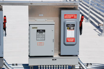
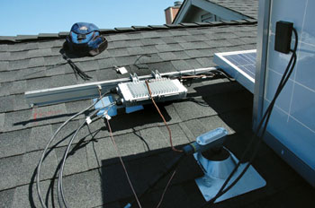
Photo 7. PV combiner with disconnect at output
However, when the fuse rating goes over 30 amps with values as high as 400 amps or more, these fuses are mounted in exposed fuse holders or bolted directly to a dc busbar. One side of each fuse is tied together with the dc input of the inverter. The other side of each fuse is hardwired to the output of a PV dc combiner and these combiners will be scattered throughout the PV array—sometimes over acres of real estate. Although the inverter can be turned off and the dc input capacitors allowed to discharge (up to five minutes), each fuse is still energized from its own input and the combined inputs of all of the other fuses through the common bus bar. The only way to safely service these fuses is to go through the entire PV array, find all of the combiners, and open or pull each and every source circuit fuse (those less-than-30 amp “finger safe” fuse holders). An optional disconnect at the output of every combiner speeds this process and makes servicing the combiner fuses safer, but all disconnects must be located and opened. (See photo 7).
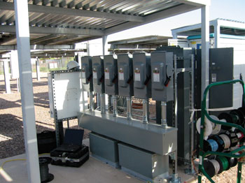
Photo 8. Disconnects for each input installed near the inverter
When these fuses are present in the input of the larger inverters, the safest way to provide for service is to install a dc disconnect near the inverter on each dc input to a fuse. (See photo 8). These collocated disconnects can be easily opened, and with the inverter turned off, the fuses can be safely removed in a de-energized state.Removedis a term used to describe prying out 400-amp fuses with a screwdriver because you have broken two plastic fuse pullers trying to remove them from those very tight fuse holders.
Summary
A detailed understanding of PV equipment and how power flows in a PV system should enable better, more thorough inspections of these systems. Better inspections will result in better, safer PV installations. We will continue with more information on the utility-interactive inverter in the next “Perspectives on PV” in our top-to-bottom tour of the PV system.
For Additional Information
If this article has raised questions, do not hesitate to contact the author by phone or e-mail. E-mail: jwiles@nmsu.edu Phone: 575-646-6105
A color copy of the latest version (1.9) of the 150-page,Photovoltaic Power Systems and the 2005 National Electrical Code: Suggested Practices, written by the author, may be downloaded from this web site: http://www.nmsu.edu/~tdi/Photovoltaics/Codes-Stds/Codes-Stds.html
The Southwest Technology Development Institute web site maintains a PV Systems Inspector/Installer Checklist and all copies of the previous “Perspectives on PV” articles for easy downloading. Copies of “Code Corner” written by the author and published inHome Power Magazineover the last 10 years are also available on this web site: http://www.nmsu.edu/~tdi/Photovoltaics/Codes-Stds/Codes-Stds.html
The author makes 6–8 hour presentations on “PV Systems and theNEC” to groups of 60 or more inspectors, electricians, electrical contractors, and PV professionals for a very nominal cost on an as-requested basis. A schedule of future presentations can be found on the IEE/SWTDI web site.