Can you recall a time when you arrived at a restaurant early and had to wait for your friend or spouse to arrive? Doesn’t that wait seem to take forever? How about waiting for that mechanic to finish up with the repairs to your vehicle? What about waiting in the checkout line at the grocery store with the nice lady in front of you sorting through all her coupons! Don’t get me started with time spent in the doctor’s waiting room. In reality, these scenarios are really short durations of time, but they seem much longer at the time. However, none of this seems to hold true when it comes to the
National Electrical Code (NEC). Perhaps because of the seemingly long development process that each edition of the NEC goes through, it seems like we have just enough time to catch our breath and the next edition is well on its way. Well, get ready, the 2011NECis right around the corner. Let’s take a closer look at some of the more substantial changes that have been proposed thus far in the NEC development process. So far, proposals have been submitted and acted upon by the different code-making panels. We are currently in the middle of the comment stage of the NEC development process where you and I have the opportunity to submit a comment on the actions taken so far on the proposals.
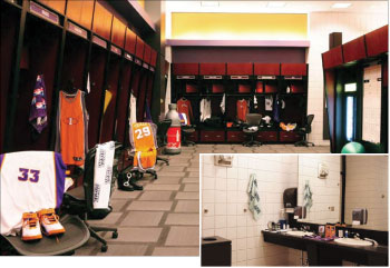
Photo 1. Locker room with adjacent showering facilitites
According to the National Fire Protection Association (NFPA), there were approximately 5,077 proposals submitted for modifications to the 2011 edition of the NEC. Of these proposals, 4,093 proposals were submitted by the public at large, while 174 proposals were developed by the code-making panels themselves during the proposal stage. As with every edition of the NEC, some of the anticipated changes include new requirements to sections while some of the changes include entirely new articles. Some changes are revisions to existing requirements while others are deletions to some existing requirements.
Code-Wide Changes
90.5(C) Mandatory Rules, Permissive Rules, and Explanatory Material.
90.5(D) Informative Annexes.
One of the first changes that one will notice is the familiar term fine print notes (FPN) has been removed throughout theCodeand replaced with Informational Notes. “Fine print” refers to a type size, rather than clearly portraying its advisory nature. TheNECcontains notes that are enforceable requirements of the code, such as table notes. “Fine print” in some legal documents does not necessarily make the text unenforceable requirements. This change will make the advisory nature of these notes clear. Also, a new section has been added at 90.5(D) introducing the concept of Informative Annexes to theNEC. Non-mandatory information relative to the use of theNECis provided in the informative annexes found in the back of theNEC. Informative annexes are not part of the enforceable requirements of theNEC, but are included for information purposes only.
Chapter One – General
Article 100 Definitions.
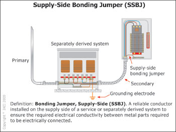
Figure 1. Supply-side bonding jumper
There were several proposals to add or revise definitions to Article 100. Some of these new or revised definitions include the following.
Automatic. Performing a function without the necessity of human intervention.
Bathroom. An area including a basin with one or more of the following: a toilet, a urinal, a tub, a shower, a foot bath, a bidet, or similar plumbing fixtures.
Bonding Jumper, Supply-Side (SSBJ). A reliable conductor installed on the supply side of a service or separately derived system to ensure the required electrical conductivity between metal parts required to be electrically connected.
Ground Fault. An unintentional, electrically conducting connection between an ungrounded conductor of an electrical circuit and the normally non–current-carrying conductors, metallic enclosures, metallic raceways, metallic equipment, or earth.
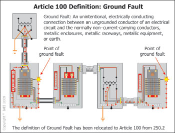
Figure 2. Ground fault definition
Grounding Electrode Conductor (GEC). A conductor used to connect the system grounded conductor, equipment, communications system protectors, antenna discharge units, communications cables, or network interface units to a grounding electrode or to a point on the grounding electrode system.
Nonautomatic. Requiring human intervention to perform a function.
Service Conductors, Overhead. The overhead conductors between the service point and the first point of connection to the service-entrance conductors at the building or other structure.
Service Conductors, Underground. The underground conductors between the service point and the first point of connection to the service-entrance conductors in a terminal box, meter or other enclosure, inside or outside the building wall. Where there is no terminal box, meter, or other enclosure, the point of connection is considered to be the point of entrance of the service conductors into the building.
Service Drop. The overhead conductors between the utility distribution system and the service point.
Service Lateral. The underground conductors between the utility distribution system and the service point.
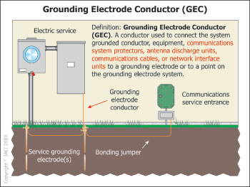
Figure 3. Gounding electrode conductor
Uninterruptible Power Supply. A power supply used to provide power to a load for some period of time in the event of a power failure. In addition, it may provide a more constant voltage and frequency supply to the load, reducing the effects of voltage and frequency variations.
Article 110 Requirements for Electrical Installations
New: 110.24 Available Fault Current.
This new section will require service equipment (other than dwelling units) to be field-marked with the amount of available short-circuit current when installed. Electrical equipment is required to have an interrupting rating or short-circuit current rating equal to or greater than the available fault current. Any equipment operating with ratings less than the available fault current is in violation of the NEC and creates a potentially unsafe condition. Knowing the available short-circuit current is an essential part of not only the installation of service equipment, but the inspection and approval of such equipment as well.
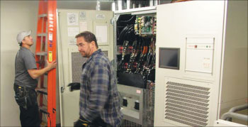
Photo 2. Large 500 kVA UPS (uninterruptible power supply) being installed in a datacenter
Chapter Two – Wiring and Protection
210.8 Ground-Fault Circuit-Interrupter Protection for Personnel.
New: 210.8(A) Dwelling Units. (Readily Accessible Locations)
New: 210.8(B) Other Than Dwelling Units. (Readily Accessible Locations)
A new requirement has been added at both 210.8(A) and (B) requiring all GFCI devices to be installed in a readily accessible location. Per manufacturer’s specifications, GFCIs are typically recommended to be tested on a monthly basis. When a GFCI device is installed behind such things as a refrigerator, the ability for someone, such as the homeowner, to test the device is greatly impaired. Installation of these devices in a readily accessible location will aid in this monthly testing process. However, on the other side of this coin, this could become an enforcement issue for the AHJ. When the AHJ typically inspects these GFCI devices on the electrical final, all these devices are typically readily accessible. The moment a bed, a dresser, or perhaps a copy machine or vending machine is placed in front of a GFCI receptacle, that receptacle just became not readily accessible (accessible, yes, but not readily accessible).
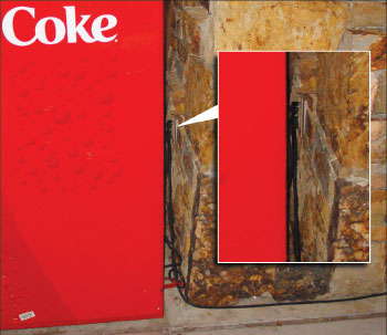
Photo 3. Ground-fault circuit-interrupter devices required to be installed in readily accessible locations (unlike what is illustrated in the above picture).
New: 210.8(B)(7) Ground-Fault Circuit-Interrupter Protection for Personnel. (Locker Rooms)
A new provision was added at 210.8(B)(7) to require GFCI protection for all 125-volt, single-phase, 15- and 20-ampere receptacles installed in locker rooms with adjacent showering facilities. Conditions in these areas very often mimic the conditions found in bathroom areas such as damp or wet flooring combined with the use of electrical appliances such as electric shavers and electric hair dryers. These are the same conditions which drive the requirements for GFCI protection in the bathroom areas.
New: 210.8(B)(8) Ground-Fault Circuit-Interrupter Protection for Personnel. (Commercial Garages)
New requirements added at 210.8(B)(8) will expand the requirements for GFCI protection for 125-volt, single-phase, 15- and 20-ampere receptacles to commercial garages, service bays, and similar areas. Currently, 511.12 would require these receptacles installed in commercial garage areas where electrical diagnostic equipment, electrical hand tools, or portable lighting equipment are used to be GFCI protected. This new requirement would apply to all 125-volt, single-phase, 15- and 20-ampere receptacles regardless of their intended use. This would apply to not only commercial garages, but service bays and similar areas.
Revision: 210.12, Ex. No. 1 Arc-Fault Circuit-Interrupter Protection for Dwelling Units.
This proposal was reported by CMP-2 “Accept in Principle” at the ROP meetings in January 2009. However, this proposal did not receive the necessary two-thirds vote at the official balloting by the principal members of CMP-2. As of this moment, this proposal is reported as “Reject.” We will have to wait and see if this proposal is altered in the comment stage. This proposal would have allowed a listed outlet branch-circuit AFCI device to be installed at the first outlet to provide protection for the remaining portion of the branch circuit without employing a metallic wiring method to the first outlet. Currently, theCodepermits a listed combination AFCI at the first outlet when the portion of the branch circuit between the branch-circuit overcurrent device and the first outlet is installed in a metallic wiring method with conditions.
New: 240.35 Marking with Available Short-Circuit Current.
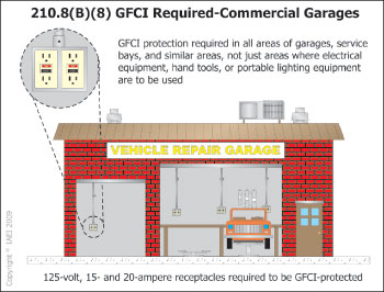
Figure 4. GFCI required in commerical garages
This is a new provision in theNECpertaining to field marking requirements that identify the available short-circuit current at equipment enclosures (other than dwelling units) containing service- or feeder-circuit overcurrent protective devices. This change will increase the enforceability of numerousNECrequirements where the electrical equipment is based on the available short-circuit current. This change will simply require that this “already-determined” value be posted on the enclosure. Along with the date on which the short-circuit calculation was performed or obtained, these marking changes apply only to the available short-circuit current as calculated for equipment rating purposes. These marking requirements for available short-circuit current do not apply for arc-flash calculation purposes.
New: 240.87 Non-Instantaneous Trip.
New language was added to Article 240 to allow a circuit breaker without an instantaneous trip to be installed primarily for selective coordination purposes, but only under very specific conditions. One of three conditions must be provided: (1) zone-selective interlocking, (2) differential relaying, or (3) energy-reducing maintenance switching with a local status indicator. Non-instantaneous trip circuit breakers or short-time delay is an industry-proven method to achieve selective coordination of circuit breakers. It delays the opening of an upstream circuit breaker while the downstream overcurrent device clears a short circuit. If, however, a short occurs between the two devices, the upstream circuit breaker will still delay its tripping operation, allowing for more let-through energy than would have been allowed if the upstream circuit breaker had utilized an instantaneous trip. This type of installation is typical for electrical power distribution systems. This extra amount of let-through energy may injure workers or damage equipment.
Revision: 250.30 Grounding Separately Derived Alternating-Current Systems.
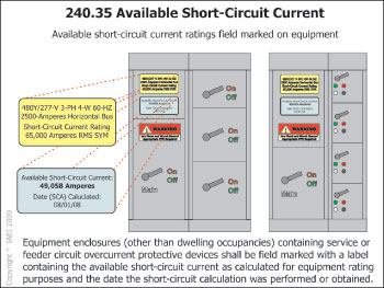
Figure 5. Available short-circuit current
Section 250.30 was extensively revised for the 2011 NEC. The revision of this section will provide a clearer understanding of the grounding and bonding requirements for separately derived systems. A new sentence has been added following the title of the section to alert users that a separately derived system must be grounded in accordance with either 250.30(A) for grounded systems or 250.30(B) for ungrounded systems. Additionally, separately derived systems must comply with 250.20, 250.21, 250.22, 250.24(A)(2) and 250.26.
New: 250.53(A)(2) Grounding Electrode System Installation – Rod, Pipe, and Plate Electrodes – Supplemental Electrode Required
Provisions were put in place to require rod, pipe, and plate grounding electrodes to be supplemented by an additional electrode of the type specified in 250.52(A)(2) through (A)(8). Currently, the only electrode that is required to be supplemented by an additional electrode is metal underground water piping. This proposed provision will essentially reverse the order of grounding electrode installation for such things as a driven ground rod. Under the current provisions of theNEC, one must install a driven ground rod and prove that it meets the 25-ohms-or-less provisions of 250.56. If the 25 ohms or less can’t be met or verified, a supplemental electrode such as a second ground rod must be installed. Few AHJs and even fewer installers possess the instruments necessary to read the resistance of a rod, pipe, or plate electrode. Under the proposed new provisions, one would start with a ground rod supplemented by perhaps a second ground rod. An exception was developed to allow only one ground rod if the 25-ohms-or-less provisions of 250.56 can be achieved and verified.
New: Use of Equipment Grounding Conductors.
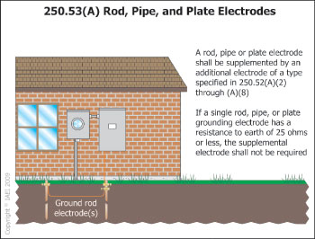
Figure 6. Rod, pipe and plate electrodes
This new provision will prohibit an equipment grounding conductor (EGC) from being used as a grounding electrode conductor (GEC). This new section will clarify that grounding electrode conductors and equipment grounding conductors serve different purposes in the electrical safety system. They are sized differently and have different installation requirements. Equipment grounding conductors do not normally carry current, while a grounding electrode conductor may normally carry current since it is often in parallel with the neutral conductor.
Chapter Three – Wiring Methods and Materials
Revision: 310.15(B) Ampacity Tables.
This revision to the Article 310 ampacity tables will put all these tables under Section 310.15, which is titled “Ampacities for Conductors 0 – 2000,” and in particular, Section 310.15(B) titled “Tables.” An example of this change will re-title the old standby table, which is perhaps the most used table in theNEC, Table 310.16 to new Table 310.15(B)(16). Existing Table 310.17 will become Table 310.15(B)(17) and so on. This change was brought about through theNEC/CEC Ampacity Harmonization Task Group.
Revision: Table 310.15(B)(2)(a) and Table 310.15(B)(2)(b) Ambient Temperature Correction Factors.
The temperature correction factor tables, which have been located at the bottom of Table 310.16 through Table 310.20, have been relocated to their own tables at Table 310.15(B)(2)(a) [based on 30°C (86°F)] and Table 310.15,(B)(2)(b) [based on 40°C (104°F)]. Acceptance of this relocation will harmonize the ampacity correction factors for various ambient temperatures between theNECand the CEC, consolidate the ampacity correction and adjustment factors into a single section [310.15(B)], and consolidate seven ambient temperature correction tables into two tables. Since the NEC is used internationally, lower and higher ambient temperatures were added to provide the appropriate ampacity correction factors for colder and warmer climates. This proposal was generated by the NFPA/CSA NEC/CEC Ampacity Harmonization Task Group.
Revision: Table 310.15(B)(6) [now Table 310.15(B)(7)] Dwelling Unit Services and Feeders.
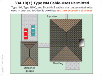
Figure 7. Type NM cable – uses permitted
Table 310.15(B)(6) [now Table 310.15(B)(7)] has once again been revised by CMP-6. Using this section, main power feeders are no longer permitted to be sized by this table. Section 310.15(B)(7) covers only service conductors and service lateral conductors. However, Section 215.2(A)(4) permits feeder conductors for individual dwelling units (or mobile homes) never to be required to be sized larger than service conductors. This section also permits Section 310.15(B)(6) [now Table 310.15(B)(7)] to be used for feeder conductor sizing. Perhaps some well-worded comments are needed for the proposed change. Additionally, Table 310.15(B)(6) only applied to 120/240-volt, 3-wire, single-phase dwelling unit services and feeders. The 3-wire reference has been removed to allow for a feeder that may have 4-wire including the equipment grounding conductor.
New: 312.10(B) Enclosure Edges.
This new requirement will require all sharp edges of Article 312 metal enclosures that are subject to hand contact during typical installation activity to be protected or de-burred and rounded to minimize the risk of injury. This shall take effect at the time of manufacture. Sharp edges on enclosures have caused numerous injuries to installers as well as thousands of lost man hours. These sharp edges have also caused damage to the integrity of conductor insulation during installation resulting in potential ground-fault conditions or sometimes immediate arc flash. However, it should also be noted that what constitutes a sharp edge is subjective, and with any subjective requirement, the code user is placed at a disadvantage when applying the requirements. CMP-9 would welcome comments on this controversial issue.
Revision: 334.10(1) Uses Permitted – Dwelling Units Accessory Structures
This is a revision that would allow the use of nonmetallic-sheathed cable (Type NM) to be used in one- and two-family dwelling accessory structures or buildings without being concealed within walls, floors, or ceilings that provide a thermal barrier of material that has at least a 15-minute finish rating. The proposed revision will clarify that Type NM cable(s) are also permitted to be used in private garages, accessory buildings, storage sheds, or similar structures that are incidental, supplemental, or secondary in nature to the one- and two-family dwelling. Lacking this clarification, the AHJ often has no choice but to consider such accessory structures as “other structures” and apply the rules of 334.10(3), whereby cables are required to be installed behind a rated thermal barrier material. With the present language, an attached garage could utilize Type NM cable as an exposed wiring method, whereas a detached garage, only a couple of feet away from the main dwelling, could not utilize Type NM cable as an exposed wiring method. Under normal circumstances, an uninhabitable accessory building should not be required to comply with rules that are more restrictive and excessive than what is required for a habitable building.
Deletion: 342.30(C) Unsupported Raceways
This change removes Item (C) Unsupported Raceways from Section 344.30 and restores the provisions of the 2005 NEC. The concept of special support rules or negating any support rules for a short length of a raceway run between enclosures was added to the 2008NEC. This change for the 2008 NEC was considered by many to be too restrictive, especially when concentric or eccentric knockouts were encountered. This change addresses intermediate metal conduit. The same change is being proposed for rigid metal conduit, rigid PVC conduit, reinforced thermosetting resin conduit, and EMT conduit.
New: Article 399 Outdoor, Overhead Conductors, Over 600 Volts
Premises wiring installations utilizing over-600-volt systems currently exist in numerous locations and have become more common as electrical usage has increased. Many of these installations utilize overhead bare conductors on insulators as feeders and branch circuits to safely distribute power to multiple building, structure and equipment locations. NEC Chapter 3 wiring methods do not currently recognize this “wiring method” nor provide prescriptive permission or limitation for these installations. This new article will allow designers of these systems to utilize existing industry standards for the specific details of such designs and will provide enforcement a basis for approval of these over-600-volt installations. This proposal was the result of the “High Voltage Task Group” appointed by the Technical Correlating Committee to look at these increasingly popular systems.
These and other changes to the 2011 NEC will be included in IAEI’s textbook entitled, Analysis of Changes NEC-2011. This book has always been and will continue to be about providing insightful firsthand information and training on impending revisions and changes to the upcoming edition of theNEC. This insight is valuable to the installer as well as to the enforcement community. This article is an effort to provide our readers a small preview of proposed changes to the subsequent edition of theNEC and to hopefully spur interest to those same readers in getting involved in the comment stage of the NEC development process. Part two of this article will be included in the next issue ofIAEI Newsand will include significant proposed changes to Chapters 4–8 of the 2011 NEC.