No discussion of PV systems would be complete without a look at the newest inverter technologies that the installer and inspector will face. These new technologies include the microinverter and the AC PV module.
Microinverters
The inverters that have been covered in the past several issues are known as string inverters because they operate with a string of series connected PV modules. These inverters range in power from one megawatt down to about 700 watts. DC maximum system voltages can get as low as about 125 volts.
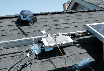
Photo 1. Enphase microinverter
The new Enphase microinverter (photos 1 and 2) is a small inverter (hence the name) that is designed to work with a single PV module and operate at a maximum of about 70 volts dc. The inverter is connected directly to the PV module using the existing conductors and connectors (now locking in most cases) attached to both the module and the inverter. Available units are rated in the 170–210 watt range, but as with other PV products, ratings and specifications change continually.
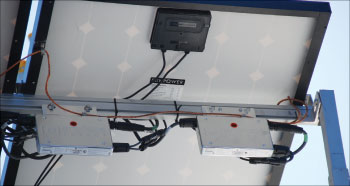
Photo 2. Pair of Enphase microinverters showing ac and dc cables
The microinverter is a utility-interactive inverter with dc ground-fault protection (690.5) in the current offering. The Enphase microinverter has been on the market since early 2009 and it internally grounds the positive dc module conductor. That internal grounding bond (via the dc ground-fault protection circuits,NEC690.5) requires that the inverter have a dc grounding electrode terminal and that terminal is on the outside of the Enphase microinverter case. Other types and brands of microinverters may accomplish grounding differently or go to an ungrounded configuration using modules with the new “PV cable” required byNEC690.35 for such systems.
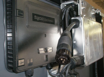
Photo 3. Microinverter AC output connector
The microinverter has ac input and output cables and connectors and has been listed in a manner that will allow multiple inverters to be connected with up to about 15 units on a single output cable. See photo 3. With a power output in the 170–210 watt range (depending on model), the rated ac output current at 240 volts will range from 0.71 amps to 0.79 amps. On the 14 AWG cable with a 15-amp overcurrent device, the rated current for that circuit is limited to a maximum of 12 amps. This rating will allow 1–15 inverters to be installed on the same ac output cable.
AC PV Modules
DC Connections
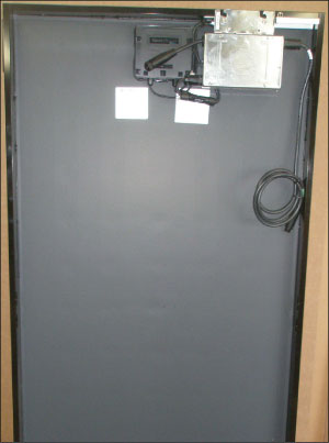
In the standard PV module/microinverter combination, the microinverter dc connection to the PV module may have to be disconnected to replace the microinverter should it or the module fail (say once in every 20–30 years). While the voltage will be a maximum of about 70 volts with current inverter designs, the current may be in 3–7 amp range and the connectors could possibly be damaged at this voltage and current, posing a possible safety hazard. While a very few inspectors may request a costly and impractical load-break rated disconnect, the code-compliant solution is really quite simple. The back of the PV module must be accessed to reach these dc connections and this generally requires that the module be unfastened from the mounting system. Since the module is accessible and is being accessed, just putting a blanket or other opaque material over it per 690.18 will reduce the dc output voltage and current (and the ac current) to near zero, allowing the module/inverter dc connectors to be safely opened. Opening this connection with the module blacked out will, in all likelihood, be safer than opening the same connectors on a module in a high-voltage string of modules. Of course, the AC PV module has no accessible dc connections.
AC Connections
Each microinverter or AC PV module will have an ac input/output cable to allow the multiple inverter parallel connections. This cable may carry currents in bright sunlight of 0.7 amps at 240 volts from the first module/inverter in the set to as much as 12 amps at 240 volts through the last connector of the set that has multiple devices. Servicing the single AC PV module or utility-interactive microinverter could be accomplished by covering the module to reduce the dc and hence the ac current to zero. However, not covering all modules in the set would allow current from other, non-covered, modules/inverter to flow through the cable and, at 240 volts, could damage the connector and possibly pose a shock hazard when opening these ac connections under load. To some extent, the hazard is minimized because the inverter anti-islanding circuits shut down very rapidly, reducing any arcing when the ac connector is opened.
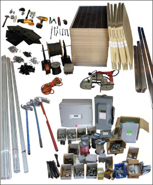
Photo 5. Numerous parts are required for a string inverter PV system
Opening the ac circuit at the PV backfed breaker in the building service entrance panel would be safe solution if that breaker could be locked open, but breaker locks are few and far between and lock-out/tag-out procedures are not generally used in residential and commercial electrical systems.
NEC690.14(D) addresses the situation and it would appear that the installation of a separate ac disconnect on the roof near the AC PV modules or microinverters will meetCoderequirements and enhance safety. A common 60-amp unfused, pull-out air conditioning disconnect costs less than $10 at the building supply centers. It provides the disconnect, a place to terminate the ac output cable from a set of microinverters or AC PV modules, a place to originate the field-installed wiring system to the ac load center in the house, and is usually cheaper than a separate junction box and cover.
Advantages
The use of microinverters and AC PV modules will proliferate due to several advantages they offer over the conventional string inverters.
The first is a simplified set of installation requirements and a reduced number of separate parts. See photos 5 and 6 for some quantitative differences in the amount and types of equipment involved in installing an AC PV Module system vs. a conventional string inverter system.
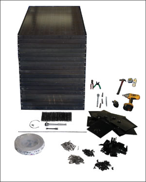
Photo 6. Far fewer parts are needed to install the Andalay PV/ microinverter system
In a dc series-connected string of PV modules, module mismatch is sometimes an issue that affects the string performance. Modules come out of the factory with slight (up to 10%) variations in specifications. The string of modules in a dc system cannot deliver current above the current delivered by the weakest module in the string. The mismatch between module currents results in some lost power compared to a dc string of modules that are equal in every specification. The PV modules near the top of an array on a sloped roof may operate hotter (and at reduced power) than modules lower down on the roof due to hot air rising behind the modules. Depending on how each string of modules is connected, some loss of power may occur if hot modules are connected in series with cooler modules.
Shading is also a problem in a conventional string-inverter configuration. The shading of a single module will result in a power loss from that module, but may also reduce power from the other, non-shaded modules in the string.
The microinverter and the AC PV module work at the individual module level. Each inverter extracts the maximum power from that module no matter what the other modules in the PV array are doing. The output of each is independent of the other modules/inverters in the set. The outputs of the microinverters or AC PV modules are connected in parallel, rather than in series, and this isolates one from another.
The outputs are at 240 volts ac and these ac output circuits act much like ac branch circuits. They go dead when the ac utility power is removed at any disconnect in the circuit so they do not pose the safety hazards associated with the daytime “always-energized” dc circuits operating at hundreds of volts between the modules and the inverter. If a short circuit or a ground fault were to occur in these ac output circuits, the dedicated branch-circuit breaker would open and the circuit would go dead. Opening the main service disconnect or the backfed PV breaker will de-energize those PV ac output circuits—a boon to fire fighters.
Disadvantages
There may be some cost impact of using AC PV modules or microinverters on each module when compared to the use of the single string inverter. However, two factors must be considered. The cost of the dc switchgear and the required conduit (or other appropriate wiring method) for the dc conductors inside the building plus the cost of the single inverter must be compared to the added cost of multiple small inverters or AC PV modules with an inverter on each module.
Then there are the life cycle costs. Modules are guaranteed for power production for 25 years, but can be expected to produce power for as long as 50 years. Large inverter manufacturers do not seem to be interested in or able to extend the average longevity past about 15 years at reasonable costs. The microinverter manufacturers, using different construction methods and topologies, are predicting significantly longer lives for their products. Time will reveal all.
A Word of Warning
The microinverter or AC PV module output must be connected on a dedicated circuit per 690.64. See the “Perspectives on PV” in recent editions of theIAEI Newsfor details on how to connect multiple sets of these devices. They should never be connected to a circuit protected by a GFCI or AFCI, because neither of these devices has been tested or listed for backfeeding.
Summary
2010 will see numerous microinverters and AC PV modules being installed. They are being sold in the home improvement centers and building supply houses as well as in local electrical supply houses, and the general public will be buying them. Inspectors must become familiar with these devices and the Code requirements that apply to them. See the author’s web site below for a white paper on connecting and grounding the Enphase microinverter.
For Additional Information
If this article has raised questions, do not hesitate to contact the author by phone or e-mail. E-mail: jwiles@nmsu.edu Phone: 575-646-6105
A color copy of the latest version (1.9) of the 150-page, Photovoltaic Power Systems and the 2005 National Electrical Code: Suggested Practices, written by the author, may be downloaded from this web site: http://www.nmsu.edu/~tdi/Photovoltaics/Codes-Stds/Codes-Stds.html
The Southwest Technology Development Institute web site maintains a PV Systems Inspector/Installer Checklist and all copies of the previous “Perspectives on PV” articles for easy downloading. Copies of “Code Corner” written by the author and published in Home Power Magazine over the last 10 years are also available on this web site: http://www.nmsu.edu/~tdi/Photovoltaics/Codes-Stds/Codes-Stds.html
The author makes 6–8 hour presentations on “PV Systems and the NEC” to groups of 60 or more inspectors, electricians, electrical contractors, and PV professionals for a very nominal cost on an as-requested basis. A schedule of future presentations can be found on the IEE/SWTDI web site.


Find Us on Socials