A transformer is an electromagnetic device without any moving parts that allows for changes in voltage, current, and impedance. The goal of an ac power network is to generate a voltage on the generation side, step up the voltage for long distance transmission on the transmission side, and then step down the voltage for distribution to the load on the distribution side. Let’s look at an example. We want to be able to transmit 1kVA (kilo volt-ampere) to a given load. We can model this scenario a few ways as shown below:
1000 V and 1 A equals 1 kVA
1 V and 1000 A equals 1 kVA
500 V and 2 A equals 1 kVA
5 V and 200 A equals 1 kVA
The question becomes which is the most efficient and practical way to transmit 1kVA to the load. The answer is high voltage and low current. The transformer allows for this to happen. Before we get into transformer theory, we should talk a little bit about power.
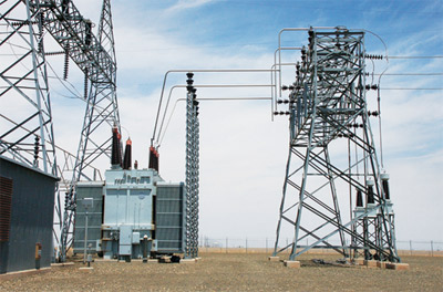
Photo 1. Utility substation
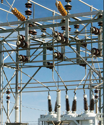
Photo 2. Utility substation
In ac circuit theory the three types of power we are interested in are real power, apparent power, and complex power. Real or true power P is expressed in watts. Apparent power S is expressed in VA (volt-amperes). Complex or reactive power Q is expressed in VAR (volt-amperes reactive). A very useful graphical tool known as the power triangle is shown in figure 1. The power triangle illustrates the relationship between the three types of power. Another term you will encounter is power factor. Power factor is the ratio between real power P and apparent power S. It is also the cosine of the angle theta as illustrated in the power triangle. Power factor is usually expressed as either a decimal or as a percentage. Loads will usually be designated in the following ways:
Resistive Load – unity power factor or 100% power factor
Inductive Load – 85% power factor lagging or .85 power factor lagging
Capacitive Load – 85% power factor leading or .85 power factor leading
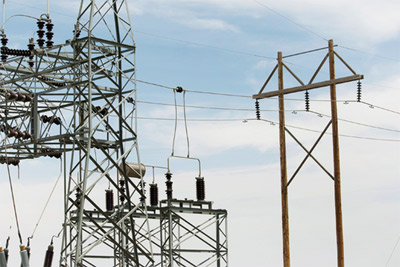
Photo 3. High voltage transmission
A review of trigonometry is in order because we will need to understand sine, cosine, and tangent functions to properly utilize the power triangle. The sine of the angle theta in the power triangle is the opposite side divided by the hypotenuse. The cosine of the angle theta in the power triangle is the adjacent side divided by the hypotenuse. The tangent of the angle theta in the power triangle is the opposite side divided by the adjacent side. Figure 2 illustrates a standard right triangle with hypotenuse, adjacent side, opposite side, and the angle theta labeled. An easy way to remember the trigonometric relationship between sides in a right triangle such as the power triangle is to recall a memory device known as the Native American Chief “SOHCAHTOA.” SOH is a way to remember the sine function. The S refers to sine, the O refers to the opposite side, and the H refers to the hypotenuse. CAH is a way to remember the cosine function. The C refers to cosine, the A refers to the adjacent side, and the H refers to the hypotenuse. TOA is a way to remember the tangent function. The T refers to tangent, the O refers to the opposite side, and the A refers to the adjacent side.
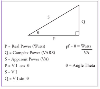
Figure 1. Power Triangle
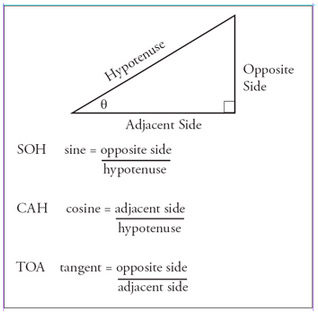
Figure 2. Standard Right Triangle
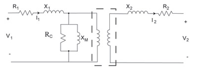
Figure 3. Transformer Equivalent Circuit
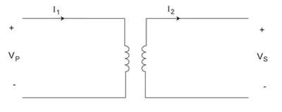
Figure 4. The Ideal Transformer
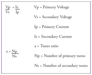
Figure 5. Ideal Transformer Equations
The equivalent circuit for an actual transformer is shown in figure 3. R1 represents the resistance of the primary winding. R2 represents the resistance of the secondary winding. X1 represents the leakage reactance of the primary winding. X2 represents the leakage reactance of the secondary winding. The core losses are represented by Rc the resistance of the core. The mutual flux of the core is represented by Xm the magnetizing reactance of the core. Sometimes this circuit is simplified by referring the secondary side to the primary, or by referring the primary side to the secondary.
For our purposes it is best to use the ideal transformer as the model. The ideal transformer is represented in figure 4. The ideal transformer assumes a perfectly efficient device with no losses. Therefore calculations become very much simplified as all you need to remember is kVA in equals kVA out. The ideal transformer allows us to easily solve for voltages and currents using Ohm’s law or any of the power equations. Figure 5 lists some common equations for the ideal transformer.
Transformers are available in single-phase and three-phase varieties. Single-phase transformers can be conventional two winding units, or they can be autotransformer connected. Three-phase transformers are available as wye- or delta-connected units depending on the application. Lastly, it is important to understand core transformer principles. In a step-up transformer, the voltage and impedance from primary to secondary is stepped up, while the current is stepped down. In a step-down transformer, the voltage and impedance from primary to secondary is stepped down, while the current is stepped up.