Question: What has a couple of poles and says “NO” when turned upside down?
Answer:A single-pole switch! Weren’t we all taught as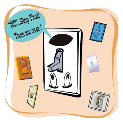 apprentice electricians and helpers that if you install a single-pole switch upside down, rather than say “ON” it will say “NO” to you! We perhaps take switches for granted. Receptacle outlets are the “face” of electrical devices, and luminaires are often grand and elegant in design and attract lots of attention. Switches on the other hand, are often over-looked unless something is not working. When you flip a switch to the “ON” position and the luminaire does not illuminate, what’s the first thing you do? The first thing we check is the light bulb. If the light bulb is OK, we might even check the connections to the luminaire while we’re up on the ladder. If the connections are OK, it must be a loose wire in the receptacle outlet just ahead of the switch in the branch circuit. Only after we check all possible failure points do we even consider that the switch itself might have gone bad. After all, that switch has worked all of the 18,235 times I’ve flipped it on before!
Switches are just not very sexy, but they are everywhere, especially in dwelling units, and the NE Chas a lot to say about these sometimes inconspicuous devices. In this article, let’s take a look at switches and their NEC requirements.
A switch is a device used to open or close an electric circuit or to change the connection of a circuit. Basically, a snap switch consists of two or more contacts mounted on an insulating assembly and arranged so that they can be moved into and out of contact with each other by a suitable operating mechanism. Switches frequently are composed of two or more single-circuit elements, known as poles, all operating simultaneously or in a predetermined sequence by the same mechanism. Switches are often distinguished by the number of poles and referred to as single-pole or double-pole switches, and so forth. Switches are typically referred to by the number of possible switch positions per pole, such as a single-throw or double-throw switch.
Some of the more common types of switch are described in table 1.
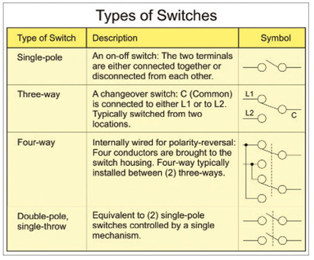
Table 1. Typical types of switches
General Provisions for and Facts Concerning Switches
Many different types of switches are installed in one- and two-family dwellings. Switches such as the single-pole, three-way, four-way, double-pole, and enclosed knife switches in the fused and unfused types are just a few examples of switches installed in dwellings.
Where surface-mounted switches are installed in any damp or wet location, such as outside of a dwelling, a switch or circuit breaker is required to be enclosed in a weatherproof enclosure or cabinet. A flush-mounted switch or circuit breaker in a damp or wet location must be equipped with a weatherproof cover. Time switches, flashers, and similar devices are required to be of the enclosed type or must be mounted in cabinets or boxes or equipment enclosures. Energized parts are required to be protected by a barrier to prevent operator exposure when making manual adjustments or switching.
A single-throw knife switch must be connected so the switch blades are not energized when the switch is in the open “off” position.
General-use and motor-circuit switches and circuit breakers, where mounted in an enclosure, must clearly indicate whether they are in the open “off” or closed “on” position. Where these switch or circuit breaker handles are operated vertically rather than rotationally or horizontally, the “up” position of the handle must be in the “on” position (see NEC 404.7).
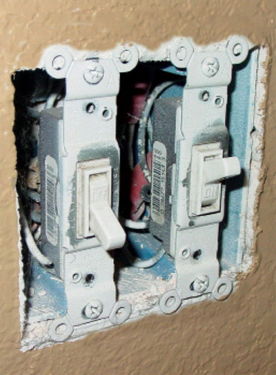
Photo 1. Switch boxes installed in noncombustible material such as gypsum are allowed to be flush or up to a 6 mm (1/4 in.) setback.
All switches and circuit breakers that are used as switches must be located so they can be operated from a readily accessible place. All switches and circuit breakers must be installed so the center of the grip of their operating handles, when in their highest position, will not be more than 2.0 m (6 ft 7 in.) above the surface of the floor or other working platform [see NEC 404.8 and 240.24(A)].
Multipole snap switches are not permitted to control more than a single circuit unless they are listed and marked for the use, or unless their voltage ratings are not less than the applied voltage of the connected circuits.
Three-way and four-way switches are required to be wired so that all switching is done only in the ungrounded circuit conductor.
Snap switches are generally required to be effectively grounded by connection to an equipment grounding conductor. In addition, the snap switch must provide a means to ground a metal faceplate. Grounding of switches is discussed in greater detail later in this article.
All snap switches mounted in boxes shall have faceplates installed so as to completely cover the opening and seat against the finished surface. Where mounted in boxes that are set back of a wall surface a maximum of 6 mm (¼ in.) (see NEC 314.20 in noncombustible walls or ceilings), a flush-type snap switch is required to be installed so the extension plaster ears are seated against the wall surface. A flush-type snap switch mounted in a box that is flush with the wall surface, or projects therefrom, is required to be installed so the mounting yoke or strap of the switch is seated against the box. Metal enclosures used for switches or circuit breakers must be properly grounded. Where nonmetallic enclosures are used with metal-armored cables or metallic conduits, provision is required to be made for grounding continuity.
A snap switch that is rated at 20 amperes or less and directly connected to aluminum conductors must be listed and marked CO/ALR [seeNEC404.14(C)].
Wiring circuitry for smoke alarms for dwelling units is to be permanent and no switch other than an overcurrent protective device is permitted in the circuit (see IRC R314).
Receptacles are not permitted to be controlled by dimmer switches. General use dimmer switches are intended for the connection of only permanently installed incandescent luminaires unless listed for other loads and installed accordingly [seeNEC404.14(E)]. See category (EOYX) in the UL General Information for Electrical Equipment (White Book) for additional information.
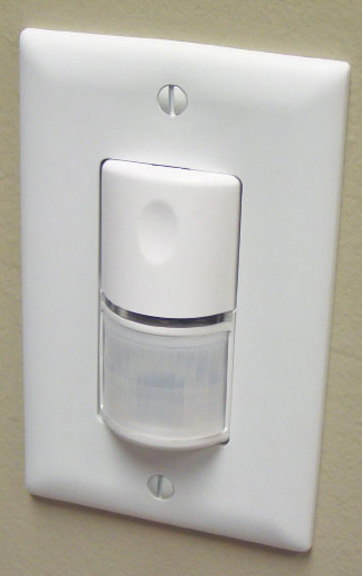
Photo 2. Typical occupancy sensor switch
A receptacle cannot be grouped or ganged in a box with other receptacles, snap switches, or similar devices, unless they are arranged so that the voltage between adjacent devices does not exceed 300 volts, or unless they are installed in boxes or enclosures equipped with identified, securely installed barriers between the receptacle and the adjacent devices [seeNEC406.5(G)].
Grounded Circuit Conductorsat Switch Locations
New requirements in the latest edition of the Code requires that where switches control lighting loads such as luminaires, ceiling paddle fans, etc., and are supplied by a general-purpose branch circuit that is grounded, the grounded circuit conductor (generally neutral conductor) for the controlled lighting circuit is required to be provided at the switch location. An exception to this requirement permits the grounded (neutral) conductor to be omitted from the switch enclosure where one of the following conditions applies:
(1) Conductors for switches controlling lighting loads enter the box through a raceway, with the raceway having sufficient cross-sectional area to accommodate adding a grounded conductor at a later date or (2) where cable assemblies such as Type NM cable enter the box through a framing cavity that is open at the top or bottom on the same floor level, or through a wall, floor, or ceiling that is unfinished on one side [see NEC 404.2(C)].
Many electronic lighting control devices, such as occupancy sensors require a standby current to maintain a ready state of detection for the function of these devices. This also allows immediate switching of the load to the “on” condition. These types of devices require standby current when they are in the “off” state as well. These devices typically utilize the grounded conductor for the standby current flow. In some situations, such as where the grounded conductor is provided at the lighting outlet location, a grounded conductor is typically not provided in the switch box for switches controlling lighting loads. When a snap switch is replaced with an occupancy sensor at a later date, installers have typically employed the equipment grounding conductor for the standby current of these control devices. This is not a good practice due to the introduction of circulating current onto the equipment grounding conductor. Occupancy sensors are permitted by UL 773A to have a current of up to 0.5 mA on the equipment grounding conductor. Current flowing at the load when the device is presumed to be off could create a potential risk to installers.
Wall Switches for Lighting Outlets Required
At least one lighting outlet controlled by a wall switch is required to be installed in every habitable room and in every bathroom of a dwelling unit. In habitable rooms, excluding kitchens and bathrooms, one or more receptacles that are controlled by a wall switch are permitted in lieu of the required lighting outlets. The NEC does not include a definition of habitable room; habitable room or habitable space is defined in the local building code. The IRC defines a habitable space as “a space in a building for living, sleeping, eating or cooking.” Bathrooms, toilet rooms, closets, halls, storage or utility spaces and similar areas are not considered habitable spaces” (see IRC Chapter 2, Section R202). Contact your local building code official for additional information.
An exception to the general rule permits control of the lighting outlet with occupancy sensors where the occupancy sensor(s) is:
- in addition to wall switches, or
- located at a customary wall switch location and equipped with a manual override that will allow the sensor to function as a wall switch.
Additional dwelling unit locations where wall switch-controlled lighting outlets are required are identified in theCode. At least one wall switch-controlled lighting outlet must be installed in hallways, attached garages, and detached garages with electrical power.
The exterior side of outdoor dwelling unit entrances or exits with grade level access must be illuminated. A remote source of illumination is permitted. No minimum amount of illumination level (foot candles) is specified. The location of the switch for these outdoor luminaires is not specified by the Code. Good work practice would suggest that these switches be located near the outdoor entrances or exits. A switch is not required at a vehicle door in a garage. A vehicle door is not considered an outdoor entrance. However, a switch can be installed at this location as an option [see NEC 210.70(A)(1) Exception No. 2].
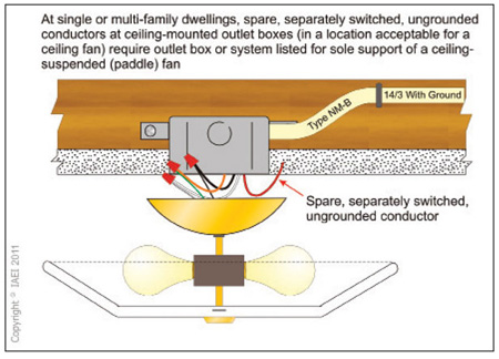
Photo 3. Spare switched conductors at ceiling box will requires ceiling fan support box.
Lighting outlets are required for dwelling unit interior stairs. No minimum illumination level is specified by the Code. The lighting outlet for interior stairs must have a wall switch at each floor level where the difference in floor levels is six or more risers (steps). In hallways, stairways, or at outdoor entrances, remote, central or automatic control of lighting is permitted. Where an intermediate landing is in the stairway and an entryway is provided at the landing location, a switch is required to control the stairway lighting at the landing location as well [see NEC 210.70(A)(2)(c)].
At least one switch-controlled lighting outlet is required for spaces such as attics, under-floor spaces, utility rooms and basements of dwelling units, where these spaces are used for storage or have equipment that requires servicing. At least one point of control must be at the usual point of entry to these spaces. No minimum illumination levels are required. A lighting outlet containing a switch may be used to meet this requirement provided a means to operate the switch, such as a pull chain, is located at the point of entry to the space.
Equipment requiring servicing includes heating and air-conditioning equipment, water heaters, central vacuum system power units, laundry equipment and similar equipment. It is not the intent of this rule to require a separate lighting outlet for equipment if other switch-controlled lighting outlets, such as room or space lighting outlets, provide adequate illumination [see NEC 210.70(A)(3)]. Similarly, illumination is required for all working spaces about service equipment and panelboards installed indoors and this light source cannot be controlled by automatic means only, such as a motion sensor. Additional lighting outlets are not required where the work space is illuminated by an adjacent light source, such as the light source for the room or garage containing the panelboard [see NEC 110.26(D)].
There are no provisions in theCoderequiring the employment of three-way or four-way switches. As stated above, theCodesimply calls for “one wall switch-controlled lighting outlet” installed in every habitable room, etc. For instance, if you had a hallway that was 3.0 m (10 ft) in length, to install a three-way switch at each end of the hallway would be a design issue and installed by choice not by NEC minimum requirements. A stairway with an intermediate landing would seem to be a place where theCodewould require two three-way switches (one at each level) and one four-way switch at the landing, but careful reading of NEC 210.70(A)(2)(c) would reveal that three single-pole switches controlling three different luminaires would satisfy this Code requirement.
Methods of Grounding Switches
The Code requires that snap switches be effectively grounded by means of connection to an equipment grounding conductor. In addition to grounding the switch, a means must be provided to ground metal faceplates. This requirement applies even if a nonmetallic faceplate is used with the switch. The intent of this requirement is to ensure proper grounding of a metal faceplate if at any time in the future, one is installed. This requirement also applies to dimmer switches. Snap switches are considered effectively grounded if either of the following conditions is met.
1. The switch is mounted with metal screws to a metal box or metal cover that is connected to an equipment grounding conductor, or the switch is mounted to a nonmetallic box that contains an integral means for connecting to an equipment grounding conductor. The Code does not require the use of “self-grounding” snap switches.
2. An equipment grounding conductor or equipment bonding jumper is connected to an equipment grounding termination of the snap switch. If multiple switches are ganged together in a single box, each switch must be bonded.
Where an equipment grounding means does not exist in the box or where the wiring method does not contain an equipment grounding conductor, a snap switch having a metal yoke is permitted to be installed without being grounded; this applies to replacement of switches only. If the switch is located within 2.5 m (8 ft) vertically, or 1.5 m (5 ft) horizontally of earth, grade, concrete floors, or other conducting surfaces, a nonmetallic cover plate must be installed. A permitted alternative is to protect the switch with a ground-fault circuit interrupter.
Listed switch kits and listed switch assemblies constructed with nonmetallic yokes and equipped with nonmetallic faceplates are not require to be grounded as well. These switches are not designed for, and have no provisions for, attaching a metallic faceplate to them. Snap switches with integral nonmetallic enclosures do not need a means of providing a connection to a metal faceplate to an equipment grounding conductor as these switches incorporate integral nonconductive (nonmetallic) faceplates and inherently cannot interchange faceplates, metal or otherwise [seeNEC404.9(B) and Exceptions].
Continuity of EGC at Switches and Other Devices
An equipment grounding conductor connection must be made so any disconnection or removal of a switch, receptacle, luminaire or other device supplied from the box will not interfere with or interrupt the equipment grounding conductor continuity downstream. This is usually accomplished by splicing the equipment grounding conductors together with short “pigtails” or bonding jumpers used to connect to the grounding terminal on each switch or receptacle. That way, the switch or receptacle can be removed without disturbing the continuity of the equipment grounding conductor (see NEC 250.148).
Switches at Tub or Shower Spaces
 Switches are not permitted to be installed within tubs or shower spaces unless installed as part of a listed tub or shower assembly. The tub or shower space is not defined in the NEC. This space is typically defined by the authority having jurisdiction (AHJ) as the signature of the tub or shower. This space might be defined as the entire space from the adjoining cabinet to the wall where the tub or shower is installed. NEC 410.10(D) defines a “900 mm (3 ft) horizontal by 2.5 m (8 ft) vertical zone” around a tub or shower, but this “zone” applies to luminaires, ceiling fans, etc., not switches. General use snap switches can be installed right next to the tub or shower space, but not within the tub or shower space [see NEC 404.4(C)].
Switches, luminaires, and other electrical equipment associated with or installed around hydromassage bathtubs are treated the same as regular bathtubs in regard to their installation requirements [see NEC 680.71].
Color Code Requirements for Switch Loops
The grounded (neutral) branch-circuit conductor is a system or circuit conductor that is intentionally grounded. This conductor is required to be specifically identified by a continuous white or gray outer finish, or by three continuous white stripes on any color other than green insulation along its entire length. The Code permits a cable containing an insulated conductor with a white or gray outer finish or a marking of three continuous white stripes to be used for the supply to single-pole, three-way, or four-way switches. If used for single-pole, three-way or four-way switch loops, the reidentified conductor can only be used for the supply to the switch but not as a return conductor from the switch to the switched outlet such as a luminaire. In this type of circuit, permanent re-identification of the white or gray conductor insulation is required. Painting, marking tape, or other effective means may be used to meet this requirement. Re-identification is required where the conductor is visible and accessible, including terminations, such as at switches, junction boxes, etc.
Remember that permission to re-identify conductors with white or gray or white-striped conductor insulation applies only to cable assemblies. The conductor with white or other identified insulation in a raceway is not permitted to be used as an ungrounded (hot) conductor. The Code does not permit painting, taping, or otherwise re-identifying individual grounded conductors run through raceways and using them as ungrounded phase or equipment grounding conductors [see NEC 200.7(C)].
Box Fill Calculations for Switch Boxes
Switch boxes and other device boxes must have adequate volume of space (cubic inches) in order to contain the required conductors and devices (switches, etc.) to be enclosed in said box. This sufficient space is needed to allow proper dissipation of heat from the contained conductors with proper air flow and circulation around the conductors.
Volume of a box is the total volume in cubic inches of the assembled sections. Where used, the space provided by plaster rings, domed covers and extension rings that are marked with their volume in cubic inches is included. If the extension ring is made of metal and corresponds to a size listed in NEC Table 314.16(A), the appropriate volume for that size box is used as the volume of the extension ring. Total volume is the volume of the box plus the volume of any attached plaster rings, extension rings, or domed cover.
This total volume (space) determines the number and size of conductors and wiring devices permitted to be contained in the box. Conductors, internal clamps, support fittings, and devices such as switches and receptacles take up space within the box. So the Code assigns to each conductor, clamp, support fitting, device and equipment grounding conductor an associated volume allowance.
Minimum requirements for device or equipment fill are also provided in the Code. A double volume allowance is required for each yoke or strap containing one or more devices or equipment. Table 314.16(B) gives the volume allowance. This volume allowance is based on the largest conductor connected to a device(s) or equipment supported by that yoke or strap.
Each device or equipment is considered individually where more than one item is contained in the box. For example, if a switch has 14 AWG conductors connected to it, a volume allowance of 2 x 2.0 cubic inches or 4 cubic inches is required. If a receptacle has 12 AWG wire connected to it, a volume allowance of 2 x 2.25 or 4.5 cubic inches must be made for that particular device.
Spare Switch Leg from Switch to Luminaire Box
Oftentimes at dwelling units, a spare switched conductor is installed at places like a bedroom switch locations to the ceiling-mounted lighting outlet in the event a ceiling fan is installed at a later date. In this situation where a spare, separately switched, ungrounded conductor is installed to a ceiling-mounted outlet box (in a location acceptable for a ceiling fan), the outlet box or outlet box system must be listed for sole support of a ceiling-suspended (paddle) fan [see NEC 314.23; 314.27(C)].
In conclusion, switches serve many and varied functions. NEC Article 404 is a good starting point to familiarize one’s self with the electrical requirements for switches. This article was intended to serve as a brief overview of these requirements. There are quite a few requirements for switches, but careful consideration to the applicable rules will go a long way in achieving satisfactory compliance…just don’t install one upside down!


Find Us on Socials