Article 250 is the largest article in the National Electrical Code. It is often the most dreaded by those new to the code, and sometimes even by those who have dealt with the code for years. Some of the terminology is confusing and conceptually difficult to follow. In keeping with the Combination Inspector emphasis of this series of articles, we will cover those items which I have previously taught to inspectors who weren’t electrical by trade. In doing so, we will not cover every section of Article 250, but concentrate on those that are used most commonly by multi-trade inspectors.
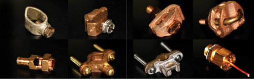
Photo 1. Here is a very small sampling of some of the devices designed for grounding connections. Please note the bottom right device will bond the grounding electrode conductor to an enclosure or raceway.
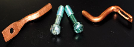
Photo 2. This shows a sampling of bonding jumpers that are provided by the factory for main bonding jumpers in panels.
Two definitions
The scope of this article covers general requirements for grounding and bonding of electrical installations. First, we have two definitions that we need to consider in order to help us understand the principles of grounding. Effective grounded-fault current path is an intentionally constructed, low-impedance electrically conductive path designed and intended to carry current under ground-fault from the point of a ground fault on a wiring system to the electrical supply source and that facilitates the operation of the overcurrent protective device or ground-fault detectors on high impedance grounded systems. Ground-fault current path is an electrically conductive path from the point of a ground fault on a wiring system through normally non-current-carrying conductors, equipment, or the earth to the electrical supply source. Both of these are best understood as the emergency path the current takes in the event of a ground fault (which is a short from an ungrounded conductor to ground). If we have a good path, then the high current flow back to the source should operate the overcurrent device and shut down the system.
As you probably noticed, the main difference is that one is an intentionally constructed path, which is what we hope to have, and the second is any path in which the current may flow. To give a real life example of this, I remember getting a service call to a house which had smoke coming out of the walls. As luck would have it, I was very close and beat the fire department to the site. The first thing I did was shut off the main at the service and the smoke started to lessen. By the time the fire department got to the house, there was hardly any visible smoke coming out of the walls, just the smell of burning wood. The fire department broke open a hole in the wall and the plaster reinforcing wire lath had been burning its way into the wood studs, just like one of the old wood burning kits we used to have as kids. The only electrical device near this part of the dwelling was an air conditioner compressor unit. I opened the junction box of the unit and the grounding wire wasn’t connected. If it had been connected, there would have been a low impedance path that carried the current back to the breaker and caused it to open. However, one ungrounded conductor had shorted out and the only path for the fault current was through the copper refrigeration lines to the wall where they contacted the metal lath wire and energized it, causing it to heat up to the point of burning the wood framing. Without a good fault-current path back to the overcurrent device, the device just sees an additional load, but not enough to make it trip in a timely fashion.
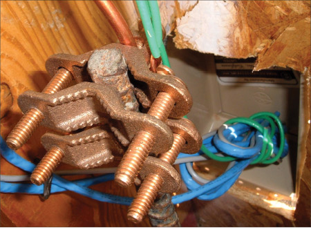
Photo 3. The bare copper conductor here is the grounding electrode conductor that has been connected to the concrete- encased electrode (rebar) stubbed up from the building footing.
Where grounding starts
Now that we understand why we need good grounding paths, let’s start back at Part III Grounding Electrode System and Grounding Electrode Conductor, since this is where grounding starts, with a good connection made to the earth. The connections to the earth are called electrodes, and the code describes eight different types of electrodes. We will only cover the concrete-encased electrodes and ground rods, since they are the ones most commonly used in construction today. Details are found in 250.52(A)(3) for the concrete-encased electrode. This is the preferred electrode for any new construction, and it performs very well due to the fact that the concrete continues to extract moisture from its surrounding soil and has great contact with the earth simply due to its weight.
The second most common is rod or pipe electrodes, which are covered in 250.52(A)(5). Ground rods are very common and make a good connection to the earth due to the fact they are required to be 8′ in length and reach deep enough into the earth. This is the best option when adding a grounding electrode system to a facility where you can’t incorporate a concrete-encased electrode.
There are other electrodes covered in 250.52 (which you should take time to read), but I will mention one that is fading from use, and that is metal underground water pipe. For decades, it was the most common source of grounding electrode; however, with the advances made in water system products, it was found that if a facility had a metal water line that failed, it was being replaced by a non-metallic system. When that occurred, we lost our grounding electrode. Even in new housing construction, I haven’t seen a metallic water pipe feeding a residence in two decades. If you review 250.53, you will find the installation methods for each of the grounding electrodes mentioned above.
One item to note is a change made in the 2011 edition of the NEC for 250.53(A)(1) related to rod electrode installations. In the 2008 NEC 250.56, it stated that a rod, pipe or plate electrode that didn’t measure 25 ohms or less would have to be supplemented by an additional electrode. In the field, this meant an inspector had to have some assurance that one device would measure 25 ohms or less, but how do you do that? Does the inspector test it? Generally no, so it was up to the contractor to prove it met this code requirement. In practice it saved time and multiple trips to the site if the contractor simply installed two rods and then didn’t have to worry about the measurement at all. So in the 2011 NEC 250.53(A)(2), it states you will install two rod electrodes, and then there is an exception which allows one rod if you prove it meets the 25 ohms or less requirement. This is a good example of how the code is often modified to match what is actually the general practice in the field.
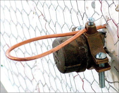
Photo 4. This is an example of 250.104, bonding of other systems. This is gas piping which goes throughout the house and may have the possibility of becoming energized and therefore shall be bonded.
Connecting to items to be grounded
So now that we have our actual connection to the earth, we have to connect it to those items we are trying to ground. To do this we use a conductor called the grounding electrode conductor. The grounding electrode conductor is covered in 250.62 through 250.68. First, this conductor must be made of a material resistant to any corrosive conditions to which it may be exposed. This could be various things, such as a corrosive soil, fumes within a building, or any other conditions that may damage it. Again, if we lose this connection to the electrode, we have totally lost our grounding system.
Article 250.64 is where we find the details on the installation of the grounding electrode conductor. Covered is how to secure and protect it, and depending on the size, it may need some physical protection such as a raceway. Please note that if protected by a metallic raceway, and the raceway isn’t continuous from the equipment to the grounding electrode, then the raceway must be bonded at each end to the grounding electrode, see 250.64(E). The reason for this is really pretty simple: the impedance of the conductor and the raceway are different and the current will travel at different speeds from one end to the other, so if they are not bonded and there is an air gap at one end or the other, it will arc. Repeated arcing will cause damage to the electrode conductor. It must be securely fastened to the surface on which it is carried and can be run through framing members. It shall be installed in one continuous length without a splice or joint; however, if it absolutely has to be spliced, there are four very specific ways to do it in 250.64(C). Remember this is a crucial element to the safety of the electrical system, and anytime we have a splice or connection we have created a possible failure point, so we try to avoid any conditions which may create a weak point.
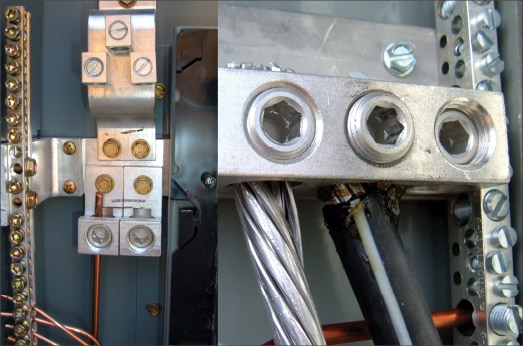
Photo 5. In both of these photos, the grounding electrode conductor is the bare copper. It is being terminated on the grounded terminal location in these residential main services. Note the aluminum bussing that continues into the meter section in each of these photos to connect directly to the utility-grounded service conductor, which meets the main bonding jumper requirement.
Also please note 250.64(D), which has allowances for a single electrode and conductor to be tapped to serve several service-entrance enclosures located in close proximity to one another. Now for one of the key elements of the grounding electrode conductor — how do we size it? In Article 250.64(D)(2) we find that each electrode conductor is to be sized according to 250.66, and there we find that generally it is sized according to Table 250.66, which lists the size of the service conductors on the line side of a service and then shows us the size of the grounding electrode conductor. The sizing is based on the size of the conductors feeding the service, since we don’t have an overcurrent device on the service conductors. Refer to Table 250.66 and also review the notes, which cover the methods for multiple sets of conductors.
Now for three applications where we don’t need to use the table and that are covered in 250.66(A), (B) and (C): these deal with conditions where we have a single conductor which is the sole connection to the grounding electrode for rod, pipe, plate, concrete-encased and ground-ring electrodes. In these sections we find a new maximum size conductor requirement for each of these types of electrodes. For example, on a concrete-encased electrode you are not required to use a conductor larger than a 4 AWG copper conductor, no matter what the size of the service. I must caution you that if the design professional has designated a larger conductor, you would be obligated to follow his requirements. Remember that the code is a minimum and can always be exceeded.
Connecting to the grounded service conductor
So now that we have the electrode and the electrode conductor, what do we do with it? In 250.24 Grounding Service-Supplied Alternating-Current Systems, we find the answer. First, in 250.24(A) System Grounding Connections, we discover that the grounding electrode conductor shall be connected to the grounded service conductor. As simple as it sounds, this is one of the most critical requirements of the code. The connection can be done in various ways as outlined in 250.24, so please follow along in the code as we go.
This should be the only point where we connect together the grounded conductor, the grounding electrode conductor and the equipment grounding conductors. This is generally done at the main service disconnecting means of a service, utilizing what is called a main bonding jumper [see 250.24(B) and 250.28]. Failure to make this connection can lead to various issues, the least of which will be voltage fluctuations that may damage connected equipment.
Once we move past the service main location, we are not to connect the grounded conductor (remember this is generally referred to as a neutral) to any grounding conductors; this is covered in 250.24(A)(5). If you do, you will create parallel ground fault return paths that may not push the overcurrent device to react in a timely fashion. Or, if you are downstream of a ground fault sensor in either a GFCI or GFP device, it will cause the device to trip.
Connecting to equipment grounding conductor
From the service, the path continues in Part VI Equipment Grounding and Equipment Grounding Conductors. In 250.110 we learn that exposed, normally non-current-carrying metal parts of fixed equipment supplied by or enclosing conductors or components that are likely to become energized shall be connected to an equipment grounding conductor. In the remainder of 250.110 and in 250.112, 114 and 116, we see some specific requirements for various types of equipment. The types of equipment grounding conductors are outlined in 250.118, and the most common would naturally be a wire-type conductor. However, you will also notice within the article that various types of raceway also meet the grounding requirements. I will not go into details of any one of these specific methods, please review for yourselves.
We need to cover 250.119 Identification of Equipment Grounding Conductors, and here we find that these conductors can be bare, covered or insulated. If covered or insulated, they shall be identified with a continuous outer finish that is either green or green with one or more yellow stripes, except as permitted elsewhere in 250.119. Those exceptions make an allowance for conductors larger than 6 AWG, which normally doesn’t come in green from the factory. We are allowed to re-identify using three options: stripping the insulation or covering, coloring or marking at the termination points. Also covered in (B) and (C) are allowances for multiconductor cablesand flexible cords.
Our next concern with equipment grounding conductors is how to properly size them. In 250.122, it states that we shall size them according to Table 250.122. This table is based on the overcurrent device that is protecting the circuit. Basically, the larger the circuit ampacity size the larger the conductor that is required to handle the fault current back to the source and to cause the overcurrent device to operate. A couple of items need to be mentioned here; one is that if the ungrounded circuit conductors are increased in size for any reason, then the related equipment grounding conductor shall be proportionally increased. This might happen if voltage drop requires a larger phase conductor, since the larger conductors will have a higher fault current capacity and we have to compensate for that with a larger equipment grounding conductor.
The other item is found in 250.122(F) Conductors in Parallel, which states that in each raceway where an equipment grounding conductor is used it must be sized in accordance with the other rules in 250.122. So if you have six PVC conduits for a parallel run, you will have to install an equipment grounding conductor in each conduit, and each must be sized according to Table 250.122. However, in the body of 250.122 we find language which states that it will never have to be larger than the ungrounded conductors.

Photo 6. This is another example of bonding piping systems. On the left the water main is bonded, and in the upper left insert we have a poor example of bonding as the connection isn’t making direct contact due to the tape. On the right, I found a fire sprinkler riser at a gas station canopy and was wondering where they made the bonding connection.
Now that we have the equipment grounding conductors run where needed, what do we do with them? The purpose of the equipment grounding conductor is again to connect any normally non-current-carrying metallic parts that may become energized in order to provide what I call the emergency electrical relief system, which is needed to open the protective devices. In Part VII Methods of Equipment Grounding, you will find the details for such things as receptacles, certain boxes, ranges and dryers to name a few; again, please review these more completely on your own.
Connecting metallic items
Bonding is covered in Part V, starting at 250.90. Bonding is simply the connection of metallic items to ensure that we have a connection to the earth. Earlier we mentioned the main bonding jumper within the service, but now we are connecting other parts of the system for the purpose of ensuring electrical continuity to safely conduct any fault current that may be imposed. In 250.96, 97, and 98, we cover the most common bonding items we need to check for on our inspections.
Bonding of enclosures, raceways, cable trays and various other items (including around loosely jointed fittings) need to be addressed. One of the most common points is at factory knock-outs where we just don’t have a good ground path. So how do we size these jumpers? It depends on if you are working on the supply side of a system or on the load side. If you are on the supply side, then you use 250.66, based on the ungrounded conductor size. On the load side, we would use 250.122, which is based on the overcurrent device size. This distinction points out a very good general rule of thumb, which is that if you have an overcurrent device upstream, go to Table 250.122; if there is no overcurrent device, go to Table 250.66.
The last bonding items are in 250.104 and 106, which cover the bonding of piping systems, exposed structural steel and lightning protections systems. Review these requirements and make sure you are getting these items properly bonded in your areas. Often this is overlooked or not properly done as we sometimes tend to get casual about these items.
Connecting to separate buildings
One item which seems to be most overlooked (in housing construction especially) is 250.32 Buildings or Structures Supplied by a Feeder(s) or Branch Circuit(s). At each separate building or structure you should make sure you have a grounding electrode installed. I know this may sound bold, but let me explain. Often these types of projects start small, and you think you are going to have a single circuit, so you use the exception. Then the plan changes and now there are multiple circuits, and it is difficult to later install an electrode. In my local area, the home builders just decided to automatically install a concrete-encased electrode no matter what the original intended use of the separate structure. At times they would only intend them as a workout room, but then they could be converted to a casita (a small house) with a bathroom and cooking equipment, so it was just easier to stub up a rebar as a grounding electrode whether we needed it or not. A little planning ahead sometimes saves a lot of headaches later on.
Insuring reliable connections
The last items to cover are found in 250.8, 10 and 12. Notice that we started at the electrode and worked our way up, and these last requirements cover methods to insure good reliable grounding and bonding connections. This includes such things as the type of components to be used, even down to the types of screws. Ground clamps, which are devices for connecting conductors to various types of building materials, shall be approved for the use and may require protection, so you will have to review the listing and installation instructions on these. Through the years, probably one area of the most creative invention has been in the grounding and bonding process. There are so many products out there and electricians don’t always have access to the proper devices and therefore try to become designers, manufacturers and installers of some of the most unique methods. If it looks a little weird, ask for the literature that should have come with the components. Lastly, we must make these connections to clean surfaces, and that may require the removal of paint or other surface coating to ensure a good metal to metal connection.
This concludes the high level coverage of Article 250. I tried to do it in a logical inspection process from the bottom up, literally. Just remember to open the code book and review it with this article, and remember that grounding is the emergency safety line. Everything electrical will generally work just fine if the ground isn’t done right, but when we have some type of abnormal issue, it is the grounding installation that saves us. This is one of the most important portions of any inspection.