According to the National Fire Protection Association, 4,012 public inputs were submitted to NFPA recommending changes from the 2014 NEC to the 2017 NEC. From those public inputs, 1,235 First Revisions were created by the different code-making panels. In this article, we will explore the most notable public inputs as a foreshadowing of the changes to come and as a catalyst for code discussions. See figure 1 for the scheduling of each step in this process. With that in mind, let’s look at some of the most notable public inputs proposed for the 2017 NEC.
New Articles
Article 425 – Fixed Resistance and Electrode Industrial Process Heating Equipment
This proposed new article provides requirements for industrial process heating equipment. At present, the NEC does not provide general and specific requirements for this equipment. The new article will apply to boilers, electrode boilers, duct heaters, strip heaters, immersion heaters, process air heaters, or other approved fixed electrical equipment used for commercial and industrial process heating. It will not apply to heating and room air-conditioning for personnel spaces.
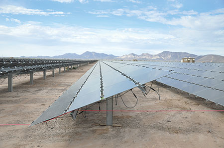
Article 691 – Large-Scale Photovoltaic (PV) Electric Supply Stations
Large-scale photovoltaic (PV) stations are designed for the supply of merchant power into the electricity grid. These stations are differentiated from most building-mounted and other decentralized solar power applications in that they supply power at the utility level, rather than to local users. They are sometimes referred to as solar farms, especially when located in agricultural areas. A utility-scale solar system is sometimes used to describe this type of large-scale project. The rapid increase in the number of large-scale PV electric supply stations presents new challenges to authorities having jurisdiction (AHJs). Due to the complexity of these systems, it is unlikely that the AHJ will have expertise in the design and construction of multi-megawatt PV power plants. Many of the components of a large-scale PV electric supply station do not and cannot comply with the current requirements of Article 690 of the NEC. According to the substantiation, the two main drivers for this proposed new article are: 1) elimination of AHJ professional risk when assessing compliance of large-scale PV electric supply stations, and 2) enabling system engineers to use engineering best practices in the design of large-scale PV electric supply stations.
Article 706 – Energy Storage Systems
This article is proposed to apply to all permanently installed energy storage systems (ESS) that may be stand-alone or interactive with other electric power production sources. An energy storage system is a device, or more than one device assembled together, capable of storing energy for use at a future time. ESS(s) include but are not limited to electrochemical storage devices (e.g., batteries), flow batteries, capacitors, and kinetic energy devices (e.g., flywheels and compressed air). These systems can have ac or dc output for utilization and can include inverters and converters to change stored energy into electrical energy. Currently, batteries are addressed in numerous places in the NEC — such as Articles 480 (historically covering lead-acid batteries) and 690 (batteries in general, not just lead acid) to PV systems, which have been appropriate over time. The current state of energy storage technology, which includes batteries, and the anticipated evolution of energy storage support the need for a singular set of requirements in the NEC covering such systems.
Article 712 – Direct-Current Microgrids
A direct-current microgrid (dc microgrid) is defined as a power distribution system consisting of one or more interconnected dc power sources, dc–dc converters, dc loads, and ac loads powered by dc–ac inverters. A dc microgrid is typically not directly connected to an ac primary source of electricity, but some dc microgrids interconnect via one or more dc–ac bi-directional converters or dc–ac inverters. DC microgrids are related to the direct utilization of power from dc sources to direct-current loads—such as LED lighting, communications equipment, computers and servers, variable-speed motor drives, HVAC equipment, etc. Direct utilization of dc—whether generated by PV systems, fuel cells or other means, without intervening dc–ac and ac–dc conversion steps—leads to higher efficiencies and potentially smaller and lower-cost equipment than AC–coupled methods. The need for higher efficiency in telecom and data centers has driven these industries to implement dc microgrids in hundreds of data centers around the world. It is a trend that will likely continue as worldwide data centers use about 30 GW of electrical power, with the USA using about 10 GW.
Chapter One – General
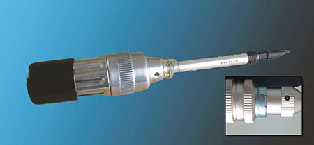
New: 110.14(D) – Electrical Equipment – Tightening Torque
A new requirement was recommended to mandate the use of a torque tool to achieve the indicated torque value at electrical equipment. Many electricians use non-torquing tools to terminate conductors on set-screw connectors in equipment. Findings of a field study presented to CMP-1 (and also published in IAEI magazine in July 2010) during the 2011 Code cycle to substantiate Informative Annex I, Recommended Tightening Torque Tables from UL Standard 486A–B, indicated that installers incorrectly tighten electrical terminations at least 75 percent of the time when not using a torque wrench. Since the reliability and safety of terminations depend on proper connection, it is essential to require the use of the proper tool. This proposed requirement would make it clear to installers and inspectors that using torque tools is required when a torque value is indicated on electrical equipment, such as a panelboard lug.
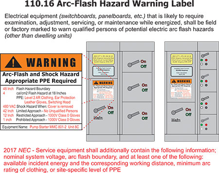
New: 110.16(B) – Arc-Flash Hazard Warning – Service Equipment
A new sub-level (B) was added to 110.16 to require additional information to be included in the arc-flash hazard warning label specifically addressing service equipment, rather than the broader application of the current text at 110.16 [proposed as 110.16(A)]. These new provisions were made based on the requirements in the 2015 edition of NFPA 70E, Standard for Electrical Safety in the Workplace. In addition to the required arc-flash labeling currently in 110.16, this new provision would require the label for service equipment to contain the nominal system voltage, arc-flash boundaries, and at least one of the following: available incident energy and the corresponding working distance, or minimum arc rating of clothing, or site-specific level of PPE. According to the substantiation, the information necessary to comply with the additional marking on service equipment is obtainable at or before the time of installation.
New: 110.21(A)(2) – Equipment Marking – Reconditioned Equipment
A new 110.21(A)(2) is being proposed to require reconditioned equipment to be marked with the name, trademark, or other descriptive marking, identifying the organization responsible for reconditioning the electrical equipment. This provision would also require the date of the reconditioning to be provided as well. This information will provide additional value to manufacturers, owners and authorities having jurisdiction (AHJs). Reconditioned, refurbished or remanufactured electrical equipment is widely used in all types of industry to be put back into service. These refurbishing marking requirements will give traceability of the equipment along with needed information to the purchaser, operator, and AHJ as to who is responsible for the reconditioning and when the work was performed.
New: 110.26(A)(4) Working Space About Electrical Equipment — Limited Access
A new provision for “Limited Access” was added to address equipment “located in a space with limited access,” such as above a suspended ceiling or in a crawl space. This new provision has four restrictions: (1) where equipment is located above a lay-in ceiling, (2) width of the limited access working space, (3) doors or hinged panels being capable of opening a minimum of 90 degrees, and (4) space in front of the enclosure. This proposal was implemented as the result of the work of a task group appointed by the NEC Correlating Committee to review requirements for working space of equipment that is often installed in spaces with limited access. The task group was charged with reviewing the revision to 424.66 during the 2014 NEC Code cycle, and exploring the feasibility of a new general requirement for the 2017 NEC in Article 110 for clarity and usability for all types of electrical equipment (not just duct heaters). Without this proposed action for limited access, it is widely understood that strict compliance with the current 110.26(A)(1), (A)(2) and (A)(3) in ceiling spaces and crawl spaces is not feasible.
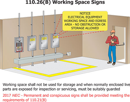
New: 110.26(A)(4) Working Space About Electrical Equipment — Clear Space Signs
New provisions are being considered for 110.26(B) calling for “permanent and conspicuous signs” to be provided when working space is required by 110.26 around and about electrical equipment. Unfortunately, electrical equipment rooms and other areas that contain electrical equipment, are often treated as the “catch-all” room for mop buckets, trash containers, and extra office equipment—such as a desk—to be stored until someone can figure out what to do with such things. This type of clutter creates a perpetual problem with keeping required work spaces around electrical equipment clear. A step toward a solution to this continual working space violation has been recommended in the form of signage. These working space signs would be required to meet the requirements of 110.21(B) for field-applied hazard markings and would need to read as follows: “NOTICE – ELECTRICAL EQUIPMENT WORKING SPACE AND EGRESS AREA – NO OBSTRUCTION OR STORAGE ALLOWED.”
Chapter Two – Wiring and Protection
Revision: 210.8(A) – GFCI Protection – Dwelling Units
GFCI protection has been proposed to be expanded in dwelling units to include not only all 125-volt, but all 250-volt, single-phase, 15- and 20-ampere receptacles installed in the locations specified in 210.8(A), as a shock hazard exists with utilization equipment at these higher voltage levels as well. Portable tools such as air compressors, miter saws, table saws that are rated at 250 volts are widely used in residential areas that see potential shock hazards from ground-fault conditions. With the addition of GFCI protection for these higher voltage receptacles that energize this type of utilization equipment, potentially life-threatening shock hazards could be avoided. It should be noted that only the voltage rating was raised to include GFCI protection. Utilization equipment such as a 250-volt, 30-ampere rated clothes dryer would not be affected by this proposed change.
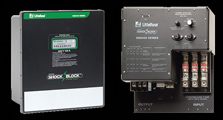
New: 210.8(B)(2)(a) – SPGFCI Protection
The opening of paragraph of 210.8(B), Other Than Dwelling Units, has been revised by adding references to new subsections, and has been subdivided into 210.8(B)(1) and 210.8(B)(2). Section 210.8(B)(1) provides the requirements for the traditional “Class A” ground-fault circuit-interrupter (GFCI) protection for personnel. The newly proposed 210.8(B)(2) provides the requirements for special purpose ground-fault circuit-interrupter (SPGFCI) protection devices. Both of these subsections have also incorporated provisions for GFCI or SPGFCI protection for three-phase receptacles in locations specified by 210.8(B). The requirements in this section have been expanded to recognize the fact that shock hazards are not limited to 15- and 20-ampere, 125-volt circuits at nondwelling unit locations. UL 943C identifies special purpose ground-fault circuit interrupters (SPGFCI) to provide personnel protection where the voltage to ground exceeds 150 volts for Class A GFCI devices. SPGFCI devices operate to trip when the current to ground is 20 mA or higher, but do not trip when the current to ground is less than 15 mA. At 20 mA or less, SPGFCI prevent fibrillation and require a reliable equipment grounding conductor in the protected circuit with an internal means within the device to monitor equipment grounding conductor continuity. SPGFCI devices addressed by UL 943C are divided into three classes—Class C, D and E—based upon voltage rating and the characteristics of the grounding circuit.
Although these devices cannot be substituted for a Class A GFCI device because of the higher tripping values (20 mA), these new classes of SPGFCI protection can provide protection at single-phase receptacle outlets where the receptacles are rated up to 100 amperes and more than 150 volts to ground, but not more than 600 volts between ungrounded conductors and three-phase receptacles rated up to 100 amperes and more than 150 volts to ground, and up to 600 volts between ungrounded conductors.

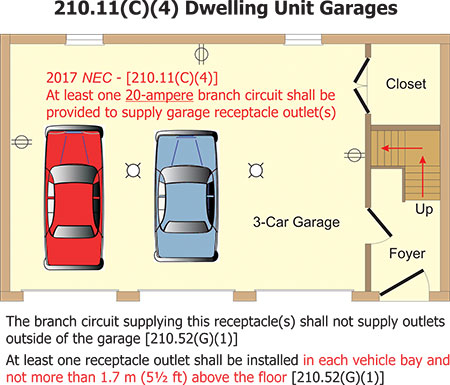
New: 210.11(C)(4) – Dwelling Units – Garage Branch Circuits
A new requirement has been proposed to require at least one 20-ampere rated branch circuit to supply dwelling unit garage 125-volt receptacle outlet(s). Previously, this branch circuit could be rated 15- or 20-ampere. Many appliances and tools used in dwelling unit garages are rated at 12- to 16-amperes or higher and demand at least a 20-ampere rated branch circuit. A 15-ampere rated branch circuit in the modern dwelling unit garage is typically not sufficient. While most residential electricians are already installing 20-ampere rated branch circuits in dwelling unit garages, the NEC currently does not require or demand this 20-ampere rating.
Revision: 210.12(A) – Whole-House AFCI Protection
The continual expansion for arc-fault circuit-interrupter (AFCI) protection appears to be complete with the proposed revisions to 210.12(A), which would require AFCI protection for all 120-volt, single-phase, 15- and 20-ampere branch circuits supplying outlets or devices installed in dwelling units. The “laundry list” of rooms or areas requiring AFCI protection was removed, leaving AFCI protection required for the entire dwelling unit. By the time the 2017 edition of the NEC is published, the electrical industry will have over 15 years of experience with the manufacture and installation of AFCI devices, and over 9 years of experience with combination-type (detects both parallel and series arcing events) AFCI devices. With the expanded requirement in the 2014 NEC, there were very few 120-volt single-phase 15- and 20-ampere branch circuits in a dwelling unit (garages and bathrooms) that did not require AFCI protection. This will accomplish the original objective sought by the US Consumer Product Safety Commission (CPSC) to reduce residential electrical wiring fires from the original AFCI proposals in the early 1990s.
CMP-2 also chose to delete 210.12(A)(4)(d), which required listing both the outlet branch-circuit (OBC) AFCI outlet device and the branch-circuit overcurrent device as a “System Combination.” This revision will basically allow the OBC AFCI outlet device to be installed at the first outlet of a branch circuit to provide the necessary AFCI protection. Substantiation for this revision provided significant statistical assurance that the “home run” portion of the branch circuit is protected from parallel arcing faults and the arcing for “hammer-damaged cable” exhibited arcing in less than 10 percent of the surge events and exhibited arcing that lasted over a single half-cycle.
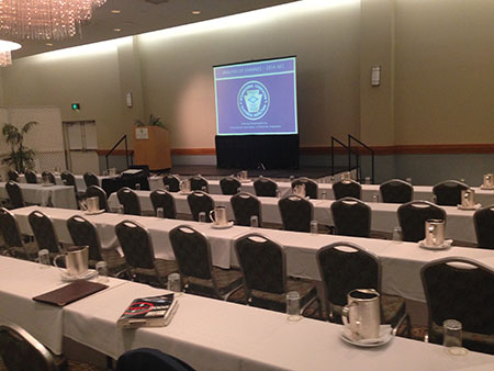
New: 210.71 – Meeting Room Receptacles
New requirements for a minimum number of nonlocking-type 125-volt, 15- and 20-ampere receptacles to be installed in nondwelling unit meeting rooms have been proposed. For meeting rooms with fixed walls, the proposed receptacle outlet provisions are similar to a dwelling unit as 210.52(A)(1) through (A)(4) are referenced. A meeting room that is at least 3.6 m (12 ft) wide and has a floor area of at least 21 m2 (225 ft2) but not more than 70 m2 (760 ft2) would have to have at least one floor receptacle at a distance not less than 1.8 m (6 ft) from any fixed wall. Meeting rooms with moveable room partitions will require at least one floor receptacle outlet to be installed for each 3.7 linear m (12 linear ft) or major fraction thereof of moveable wall measured horizontally along the floor line. These floor receptacle outlets would need to be located within 450 mm (18 in.) of the movable partitions. Currently, there is no NEC requirement to provide receptacle outlets in meeting rooms of commercial occupancies. A design that complies with the current minimum NEC requirements could result in a meeting room with no receptacle outlets at all. This proposal addresses the inherent concerns relating to inadequate access to electrical power in meeting rooms. Receptacle outlets are needed to provide power along wall lines for laptop computers, displays, coffee pots, heating of catered food, and other electrical/electronic equipment.
Revision: 230.29 – Overhead Service Conductors – Supports Over Buildings
Revisions to 230.29 will require metal support racks or structures to be bonded by means of a bonding jumper and listed connector to the grounded overhead service conductor for grounded systems. The bonding jumper used for this bonding purpose would be required to be of the same conductor size and material as the grounded overhead service conductor. Metal racks or structures that are mounted on a roof or adjacent to a building and used to support energized conductors should be adequately bonded to limit potential shock hazards. Currently, there appears to be nothing in the NEC that would require these roof supports be bonded as they are not part of a service raceway or enclosure. This proposed language will provide installers clear bonding provisions and the AHJ a clear requirement for enforcement.
New: 240.67 – Arc Energy Reduction (Fuses)
New provisions have been proposed to provide arc energy reduction methods of incident energy reduction for fusible switches. The benefits of an arc energy reduction requirement that reduces incident energy for circuit breakers rated 1200 amperes and greater have been well-established at 240.87. Those same methods of incident energy reduction could also be utilized with 1200 amperes and greater fusible switches. The proposed requirements of 240.67 are based upon the requirements in 240.87 for circuit breakers, but modified to work with fusible switches. Section 240.67(A) details the necessary documentation, and 240.67(B) addresses methods to reduce clearing times. It should be noted that this arc energy reduction requirement for fusible switches has a proposed future effective date of January 1, 2020. While de-energizing electrical equipment prior to examination or work within that equipment is the preferred procedure, NFPA 70E, Standard for Electrical Safety in the Workplace, recognizes and permits workers to perform some tasks within energized equipment. As with circuit breakers and 240.87, this new proposed requirement is intended to provide a reduced clearing time when and where justified energized work may be necessarily performed on equipment supplied by a fusible switch of 1200 amperes or greater.
Revision: 250.30(A)(4) – Grounding Separately Derived AC Systems – Grounding Electrode System
Revisions were accepted for the acceptable methods of providing a grounding electrode system for a separately derived system from a grounded system. Current text at 250.30(A)(4) instills a “pecking order” for acceptable grounding electrodes for a separately derived system. Currently, “the grounding electrode shall be the nearest of one of the following: a metal water pipe grounding electrode or a structural metal grounding electrode.” If these two “are not available,” an exception will then allow “any of the other electrodes identified in 250.52(A) to be used if the two electrodes mentioned above are not available.” The new proposed text at 250.30(A)(4) will allow any of the building or structure grounding electrodes described at 250.52(A) to be used as the grounding electrode for the separately derived system without an order of preference. The revised language also recognizes the water pipe and the structural metal frame as covered in 250.68(C) are not actually grounding electrodes but rather are conductors extending the grounding electrode connection.
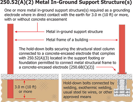
Revision: 250.52(A)(2) – Grounding Electrodes – Metal In-Ground Support Structure(s)
Section 250.52(A) describes the conducting objects that are required to be used in a grounding electrode system with the prevailing conditions for each electrode described. In recent code cycles, performance criteria for these electrodes have been relocated to 250.68(C), leaving only qualifying conditions. The qualifying conditions for a metal frame of a building or structure [located at 250.52(A)(2)] have gone through numerous changes since the 2002 NEC and beyond. Two conditions exist in the 2014 NEC in order for a metal frame of a building or structure to qualify as a grounding electrode. The proposed text for the 2017 NEC leaves only one condition: one or more metal in-ground support structure(s) in direct contact with the earth vertically for 3.0 m (10 ft) or more, with or without concrete encasement. The title of this subsection will change to “Metal In-Ground Support Structure(s)” to better reflect the definition of a grounding electrode, and the text will be revised to provide clarity for describing what this electrode is. The current text regarding “hold-down” bolts will be relocated to 250.68(C)(2) as performance criteria, not a qualifying condition. Typically, if a metal frame of a building or structure is driven into the ground and extends above the ground for any length, a transition from grounding electrode to grounding electrode conductor is made at the point of emergence from the earth.
New: 250.52(B)(3) – Not Permitted for Use as Grounding Electrodes
Decisive language was proposed that would prohibit the structures and/or structural reinforcing steel of an in-ground swimming pool described at 680.26(B)(1) and (B)(2) from being used as a grounding electrode for a building or structure. Detached buildings or structures with electrical power from a feeder—such as detached garages, workshops, etc.—need a grounding electrode system installed per the requirements of 250.32(A). Occasionally, these detached structures are located near in-ground permanently installed swimming pools. In certain areas of the country, the electrical installer will run a grounding electrode conductor from the electrical subpanel at the detached structure to the reinforcing steel of the conductive pool shell (belly steel) or to the structural steel of the perimeter surfaces (deck steel) and classify the pool reinforcing steel as an “other local metal underground system or structure” as described at 250.52(A)(8). Sometimes, this action is at the request of the local AHJ. This practice of using a swimming pool structure as a grounding electrode would make the swimming pool in question (and its inhabitants) a “super target” for any stray currents or ground-fault current introduced on this grounding electrode system. CMP-5 determined that it was never the intent of the NEC to use a pool bonding grid as a grounding electrode.
Chapter Three – Wiring Methods
Revision: Table 300.5 – Minimum Cover Requirements
A new “General Note” to Table 300.5 has been recommended to resolve a potential conflict between UL 1838, Standard for Safety for Low Voltage Landscape Lighting Systems, and Table 300.5. The proposed footnote would read, “A lesser depth [other than specified by Table 300.5] shall be permitted where specified in the installation instructions of a listed low-voltage lighting system.” UL 1838 permits the use of junior and hard service cords that are not rated for direct burial. As such, UL 1838 requires that the installation instructions inform the installer that the main secondary wiring is intended for shallow burial [less 150 mm (6 in.)], unless the manufacturer has provided wiring intended for direct burial. This appears to create a conflict between NEC 110.3(B) and Table 300.5 (column 5, row 1) since the installation instructions of listed equipment are to be followed. Per UL 1838, a conductor not identified as direct burial is to be buried less than 150 mm (6 in.); but Table 300.5 column 5 row 1 requires low-voltage landscape lighting conductors to be buried at a minimum of 150 mm (6 in.). The proposed new footnote to the table will eliminate the conflict between Table 300.5 for listed landscape lighting systems that present no significant risk of fire or electric shock injury and are intended to be easily accessed for repair or replacement.
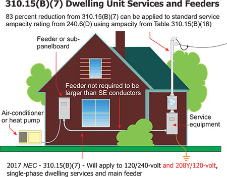
Revision: 310.15(B)(7) – Sizing Dwelling Unit Services and Feeders
For the decades that this dwelling unit service conductor sizing provision has existed in the NEC, it has always applied to 120/240-volt, single-phase services and limited feeders only. For the 2017 NEC, a First Revision will allow the reduction in size for dwelling unit service conductors and a feeder that supplies the entire dwelling to also include systems of a 120/208-volt system to qualify as well. The original data that was used to establish the dwelling unit service conductor reduction requirements of 310.15(B)(7) was actual utility company data for 120/240-volt 3-wire single-phase systems only. Previous attempts to include 120/208-volt systems at 310.15(B)(7) have met with the argument that the grounded (neutral) conductor of a 208-volt system, which supplies only two phases of a three-phase Wye system will carry near full-line current. Other arguments against inclusion of a 120/208-volt system have included objections to the additional heat from the presence of a third current-carrying conductor as the grounded (neutral) conductor in a 120/208-volt system is a current-carrying conductor. This will be an interesting proposed revision to watch during the public comment stage.
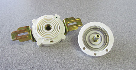
New: 314.27(E) Outlet Boxes – Separable Attachment Fittings
A new subsection (E) has been proposed for 314.27 to address new technology incorporating listed power supply devices, and listed locking support, and mounting receptacles and supporting means for luminaires and ceiling-suspended paddle fans to be installed in or to boxes designed for the purpose. These fittings may now be used to support and power the luminaire or ceiling-suspended paddle fan directly, thus facilitating replacement of the luminaire or ceiling-suspended paddle fan when attached in or to the box described at 314.27. This new subsection recognizes new listed technology designed to power and support luminaires and/or ceiling-suspended paddle fans from a receptacle and mounting means located in the box, rather than by direct connection to the box. This listed product will provide a secure mounting mechanism and will facilitate interchange of luminaires and ceiling-suspended paddle fans in a safe and efficient manner. It should be noted that this new language concerning locking support and mounting receptacles for luminaires is an option and not a requirement for mounting luminaires and ceiling-suspended paddle fans.
New: 320.6 – Listing Requirements – Cable Wiring Methods
New provisions have been proposed to be added at .06 of several of the cable-type wiring method articles that would require the wiring method (cable) and associated fittings to be listed and labeled. Listing is based on compliance with recognized product standards. Non-listed cables and associated fittings may not have been evaluated for compliance with such requirements; and, in some cases, lack of such compliance may make it difficult to determine acceptance in the field. For example, a non-listed cable may not function correctly with listed termination fittings. This proposed text will ensure that the cable will be evaluated to the appropriate product standard and be listed for use in accordance with the NEC. The addition of the words “and labeled” will insure that the AHJ has clear evidence that the wiring method and fittings are listed by an acceptable product evaluation organization. This new listing requirement was proposed for 320.6 Type AC cable; 322.6 Type FC cable; 324.6 Type FCC cable; 328.6 Type MV cable; 330.6 Type MC cable; 332.6 Type MI cable; 334.6 Type NM cable; 336.6 Type TC cable; 338.6 Type SE cable; and 340.6 Type UF cable.
Revision: 338.10(B)(4) Uses Permitted – Type SE Cable
Provisions have been proposed to limit the restriction of service-entrance (SE) cables ampacity ratings to the 60°C (140°F) conductor temperature rating to only 10 AWG sizes and smaller, where the Type SE cable is installed in thermal insulation as a branch circuit or feeder. The current restriction applies to all sizes of Type SE cable installed in this manner. This change will align smaller Type SE cables with Type NM cables as related to heat dissipation when installed in thermal insulation. Type SE cable is listed according to UL 854 and is typically listed at 75°C with 90°C insulated conductors. Type SE cable is commonly available in copper 8 AWG and larger and aluminum 6 AWG and larger. The smaller sizes are often used in residential applications to feed large appliances, such as rangetops and ovens. The limitations to 60°C should only apply to sizes used for small conductor installations. Appliance receptacles sized 30 amperes and larger are listed and marked for use at 75°C with both copper and aluminum. Therefore, the circuit breaker, Type SE cable and receptacles are all suitable for use at 75°C. Type NM cable is frequently used for smaller devices, such as receptacles and switches that are listed for use at 60°C. If Type SE cable is used for a similar installation, it would be reasonable to limit its ampacity to correlate with the temperature limitations of the devices and luminaires. There seems to be no logical or technical reason to restrict larger sizes of Type SE cable ampacity for larger conductor applications.
New: 366.20 Auxiliary Gutters – Conductors Connected in Parallel
New language was proposed for Article 366 with specific instruction on installing conductors in parallel in auxiliary gutters. There have been documented failures of parallel phase conductors due to inductive heating, where installed in wireways or auxiliary gutters. In addition to the requirement of each parallel phase conductor being the same length, the proper grouping of phases can reduce inductive heating and result in a more balanced load between each conductor of a parallel phase. Specific language requires parallel conductors to be installed in groups consisting of not more than one conductor per phase, neutral, or grounded conductor to prevent current imbalance in the paralleled conductors due to inductive reactance. The same parallel provisions were also proposed for metal wireways at 376.20 and for nonmetallic wireways at 378.20
This article provides readers with current information about proposed First Revisions (FRs) that have been approved thus far in the 2017 NEC Code development process. To become part of the “First Draft” edition of the 2017 NEC, these FRs need a 2/3 majority vote. Some of the changes we have reported on might not receive that 2/3 majority vote in the written ballot. Other proposed changes have the opportunity to be reversed by a Public Comment (PC), which will be open from July through September 25, 2015 (electronic submittal).
Part 2 of this article, covering changes in Chapters 4–8, will appear in the July-August issue of IAEI magazine.
2017 NEC Development Timeline
January 2015
Hilton Head Island, South Carolina: First Draft Meeting 19 Code-making panels
4,012 public inputs (PI) recommending changes from 2014 NEC to 2017 NEC
1,235 First Revisions
9 proposed new articles, 4 of which received favorable recommendation to move forward to First Draft consideration
Article 425 Fixed Resistance and Electrode Industrial Process Heating Equipment
Article 691 Large-Scale Photovoltaic (PV) Electric Supply Stations
Article 706 Energy Storage Systems
Article 712 Direct Current Mircrogrids
First Draft Edition of 2017 NEC
Requirement: 2/3 majority vote needed from CMP members for inclusion in First Draft (letter ballot)
Deadline for letter ballot was March 31, 2015.
Public Comment
July 1 –September 25, 2015
Opportunity to comment on First Drafts
November 2015 San Diego: Second Draft Meeting