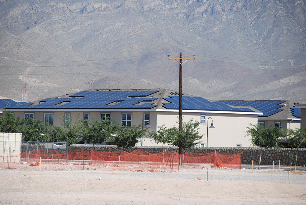
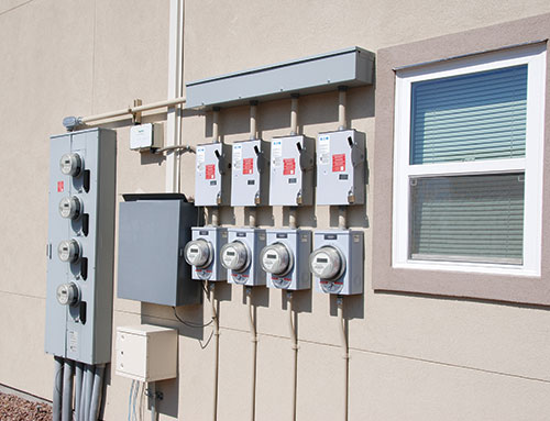
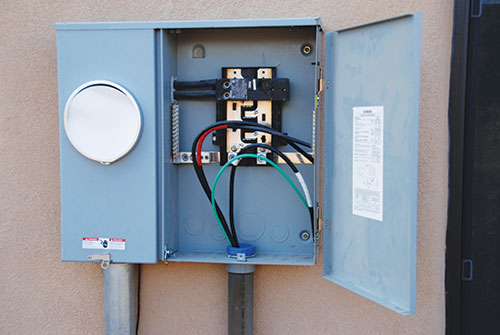
Continuing decreases in the cost of photovoltaic (PV) power systems have resulted in residential and commercial PV systems that are increasing in size and power output. The lead-in photo shows a condo community with PV covering nearly all available roof area; and yes, pointing in several different directions. These larger systems are frequently too large to be connected on the load side of the premises main service disconnecting means. They are therefore being commonly connected to the supply side of the main service disconnect (photo 1). Requirements in the National Electrical Code (NEC), guidance from NFPA personnel, and local jurisdictional requirements and/or local practice make the overall requirements for supply-side connected PV systems at least as complex as the connections for load-side connected PV systems. The written Code requirements should be reviewed first, and there are some changes in the 2017 Code.
NEC Requirements
Section 705.12 (A) is the basic Code section that allows an electric power source (including a PV system) to be connected onto the supply side of the service disconnecting means. This section also refers to the permissive allowance for such a connection in section 230.82 (6). To avoid overloading the service, the sum of all the ratings of all overcurrent devices connected to power production sources shall not exceed the rating of the service.
Although section 230.40 restricts each set of service conductors or service drop to supply only one set of service-entrance conductors, Exception 5 allows each set of service-entrance conductors connected to the supply side of the normal service disconnecting means to supply the systems described in 230.82 (6). Note that although the Code refers to “supplying” these PV connections, actually the utility-interactive PV system supplies the utility with energy. This fact results in some confusion as to how to deal with these connections.
Section 230.82 (6) permits the following equipment to be installed on the supply side of the service disconnecting means: Solar photovoltaic systems, fuel cell systems, wind electric systems, energy storage systems, or interconnected power production sources. From time to time, NFPA engineers have called these PV output conductors PV feeders. Unfortunately, since there is no overcurrent protection in the premises wiring protecting these conductors at their source, they do not appear to meet the definition of a feeder as defined in Article 100 and described in Section 240.21.
“Feeder. All circuit conductors between the service equipment, the source of a separately derived system, or other power supply source and the final branch-circuit overcurrent device.”
Based on the 2017 NEC and previous editions of the Code, it appears that it will be left to the AHJ working with the PV system installer to determine the size and protection of these conductors from the actual point of connection to the service entrance conductors and the first overcurrent device on this circuit.
Section 705.31 provides some guidance in this area but not does not specifically address the conductor, however short, between the actual point of connection and the first overcurrent device. This section, possibly being revised for 2020 edition of the Code, requires that an overcurrent protective device be located within 3 m (10 ft) of the point where these conductors are connected to the service. An exception to this requirement allows a more distant overcurrent device location where either cable limiters or current limiting circuit breakers are installed in each ungrounded conductor at the actual point of connection to the service entrance conductors. As noted in the previous article in this series, cable limiters function differently from current limiting circuit breakers even though both devices have current limiting capabilities. The current limiting circuit breaker would establish the beginning (or the end depending on viewpoint) of the PV system output circuit since it provides both overcurrent protection/overload protection and a disconnecting means at the connection point to the service entrance conductors. Cable limiters cannot provide overload protection and have no disconnect function. With a possible 3 m (10 ft) cable length allowance, the issue of sizing protecting and routing the conductors connected directly to the service entrance conductors must be addressed.
Because these conductors are subjected to the full available fault current from the utility just as the service entrance conductors are, the author suggests that these conductors use the cable types and wiring methods allowed for service-entrance conductors (230.43) and be routed, sized and protected (230.50) in the same manner as service-entrance conductors up to the first overcurrent protective device.
PV System Output AC Disconnect
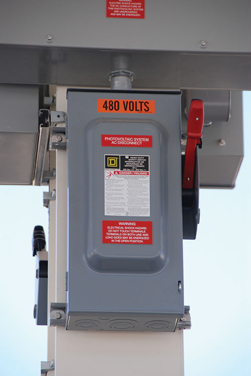
The PV system ac output disconnecting means must be located in a readily accessible location [690.13 (A)] and be listed as suitable for use as service equipment [690.13 (C)]. See photo 2. The disconnecting means must be rated for the maximum circuit current available, the short-circuit current and the voltage of the circuit [690.13(E)]. Each PV system may have up to six disconnecting means (either circuit breakers or switches). Where there are more than six PV inverter outputs, multiple inverter outputs may be combined into a single circuit and up to six of these single circuits and their corresponding disconnecting means are allowed for each PV system [690.13(D)]. It should be noted that this Code section and the accompanying comments in the 2017 NEC Handbook do not fully clarify or integrate this allowance for six PV system disconnects with the limit of six disconnects for the service (230.71) where supply-side PV system connections are involved.
Most, but not all, utility companies require a visible blade, lockable open disconnect switch (a.k.a. safety switch) as the first disconnect after the PV circuit connection point to the service entrance conductors (photo 3). The utility will establish requirements for the location and marking of this switch. This utility requirement is in addition to the requirements of the NEC with regard to PV system disconnects, however, if the utility disconnecting means is in a suitable location and meets other Code requirements, it can be used as the PV system ac disconnect. A few utilities, primarily in California, do not require this disconnect switch and they instead rely on the anti-islanding safety features built into the utility interactive inverter to disconnect the inverter from the utility lines or cease exporting power to the utility when the utility lines are not powered.
It should be noted that all ac PV circuits after the first supply-side connected overcurrent device/disconnect and back toward the inverter ac output(s) are now considered load-side (of the service (PV) disconnect) circuits and must follow the requirements of section 705.12(B) where busbars, overcurrent devices and feeders are involved.
Inverter AC Output Circuit
The circuit from the ac output terminals of the inverter to the first overcurrent protection device is sized according to the requirements of 690.8 and 690.9. Essentially, that circuit ampacity is based on 125% or conditions of use factors applied to the rated output current of the inverter and the 125% factor relates not only the conductor size but the rating of the overcurrent device protecting the conductor. The inverter installation manual will designate a maximum allowable overcurrent device in the ac output circuit. This requirement is stated in the manual and is a UL certification/listing requirement because frequently the external overcurrent device in the ac inverter output circuit is used to protect internal components in the inverter.
Supply-Side Connections Inside Panelboards
Where there is sufficient room (cubic inches of volume) in a main panelboard/load center near the incoming service entrance conductors, a supply-side connection may be made in this area. Various types of splicing devices are available and in some cases, it is possible to find a panelboard where the main input lugs have been designed to accept parallel conductors for each of the phases. If extra unused terminals are available on each input phase, or the terminals are suitable for double lugging and have not been so used, then the supply-side PV connection could be made to these terminals.
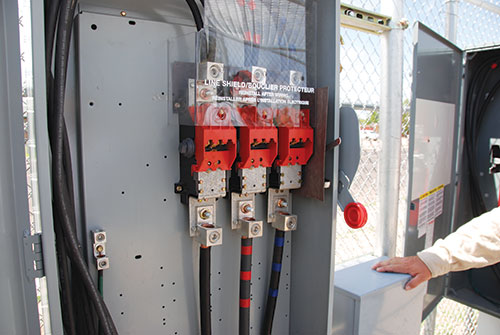
Connections inside a meter-main combo panel between the meter socket and the main breaker are generally not permitted because such a connection would violate the certification/listing on the product (photo 4). Such connections are tempting because of the ready access to either exposed cables or exposed busbars. However, without the manufacturer’s specific permission, instructions, hardware, and specifications, these connections cannot be made. And, where connections have been approved and authorized by the meter-main combo manufacturer, extreme care must be exercised in selecting the PV circuit conductors and providing a nearby location for the overcurrent protection and PV system disconnect for these conductors which are, as before, subjected to the full available fault current from the service.
Main-Lug-Only and Special Panelboards
MLO Panelboards. In some parts of the country, residential electrical systems have no main breaker but have a main-lug-only (MLO) service entrance panel with up to six main breakers connected to the busbar. Each of these breakers feeds either a large load like an electric oven or an air conditioner or a subpanel for general purpose receptacle outlets and lighting. In many cases the MLO panel has only six breaker positions. If one of these six breaker positions were not being used for load circuits, it may have been used for a supply-side PV connection and the rating of the backfed PV breaker may be up to the rating of the busbar or the service whichever is lower. Note that the six motions of the hand “rule” has been met relating to the requirement to disconnect all sources of power with no more than six switches or six circuit breakers (230.71).
An interesting situation occurs when a main-lug-only panel has more than six available breaker positions. If six of the positions are occupied with breakers supplying load circuits, what is the status of a seventh main breaker position that might be added as a backfed breaker for the output of a PV system? The first sentence in Section 230.71 is as follows:
“(A) General. The service disconnecting means for each service permitted by 230.2, or for each set of service-entrance conductors permitted by 230.40, Exception No. 1, 3, 4, or 5, shall consist of not more than six switches or sets of circuit breakers, or a combination of not more than six switches and sets of circuit breakers, mounted in a single enclosure, in a group of separate enclosures, or in or on a switchboard or in switchgear. There shall be not more than six sets of disconnects per service grouped in any one location.”
It would appear that the seventh breaker used as a PV supply-side disconnect would violate the six switch/breaker rule at any one location. But, we still have that nagging allowance in 690.13 that allows up to six disconnects for the PV system. However, consider the situation where the PV disconnect switch or breaker for a supply-side connection is located outside of the existing main-lug-only panelboard, is connected to a set of feedthrough lugs on the busbar and is some distance possibly inches to feet away. The AHJ would have to determine whether this PV disconnect was close enough to the existing six, load breaker disconnects in the MLO panel to be considered grouped at a single location. In a similar manner, some consideration might be given to seventh PV disconnect breaker located at the bottom of a large MLO panel where the six load breakers were at the top of the panel and there were no other breakers in the panel. Most AHJs would consider this grouped in one location and disallow the seventh PV breaker.
Overall safety may be the deciding factor. If no more than six motions of the hand are allowed to disconnect all conductors in a structure from the service at one location, then it would appear that seventh PV disconnect would not be allowed if the AHJ determines that it is grouped with the six, load breaker disconnects. Where the seventh PV disconnect is determined to not be grouped with the six, load breaker service disconnects, then each of these separately located disconnecting means must be well marked with directories or plaques (705.10).
Ranch Panels. In certain parts of the country, a so-called “ranch panel” has been installed which would typically be a load center rated at 400 A with two, 200 A main breaker positions. One main breaker output is connected directly to a busbar with a set of load circuit breakers in the panel and a second main breaker position is free for other uses such as a water pump or remote load center. The second main breaker position, if unused, may be used to make a PV supply-side connection. The rating of the busbars, the service and the maximum acceptable main breaker in the extra position will determine the amount of supply-side backfed PV that can be connected. As in other situations, circuits connected after the main breaker must follow the requirements of load-side connected PV systems as stated in Section 705.12(B).
Meter Socket Adapters
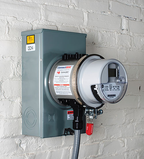
Several manufacturers have developed and are selling listed meter socket adapters that, after removing the meter from its socket or base, plug-in to the socket and the meter plugs into the adapter (photo 5). The adapter has internal connections and readily accessible terminals that can be used for a supply-side PV connection. Some utilities do not permit this type of adapter to be used, but where it is accepted, the supply-side connection is easy to make and it is usually possible to mount the ac PV system disconnect either utility required or NEC required or both in close proximity to the existing meter location. In many cases, the utility will also require a production meter or renewable energy credit (REC) meter in the same circuit as the PV inverter output. Where this meter is required, it is usually located adjacent to or within a few feet of the existing revenue meter. As noted previously, the utility will control the location and connection sequence of these products.
In the meter base. In jurisdictions, where allowed by the utility, a supply-side connection may be made on the output lugs all the meter socket where those lugs are suitable for double lugging. In some cases, the meter socket output lugs may be exchanged for factory lugs that are suitable for double lugging.
Bonding and Grounding
The bonding and grounding requirements associated with the PV system ac disconnect for a supply-side connected PV system are to some extent determined by the local jurisdiction. The NEC is not explicit in this area. The following considerations should be noted in establishing any requirements for grounding and bonding.
As mentioned above, the ac PV system disconnect should be listed as being suitable for service entrance use. This generally indicates that there is a provision for a neutral-to-ground bonding jumper in the disconnect and that the disconnect has suitable ratings for being connected to unprotected service conductors.
It would appear that if the supply-side PV disconnect is a circuit breaker in a main lug-only-panel where there is already a bonding jumper for the other main disconnects in that panel, no additional bond from neutral to ground would be required. See Exhibit 250.11 in the 2017 NEC Handbook.
As the distance between the new supply-side PV AC system disconnect and the existing main disconnect increases, the need for a bonding jumper between the neutral conductor and ground may increase. Some AHJs may look at the addition of second bonding jumper and determine that there is the potential for undesirable neutral currents to flow in the equipment grounding conductors and the grounding electrode conductors where a second bonding jumper has been added for the PV system. However, an examination of Exhibits 250.10, 250.12 and 250.34 in the 2017 NEC Handbook indicates that this is not a problem where the various disconnects and bonding jumpers are in close proximity and where the metallic conduits probably carry only an inconsequential part, if any, of the neutral currents because the resistivity of steel conduits is considerably higher than the resistivity of the copper conductors involved.
Even when metallic raceways are not used in connecting the various pieces of the service entrance equipment and disconnecting means in the supply-side connections, there appears to be no Code requirement to extend an equipment grounding conductor from either the existing main disconnect or an added PV system disconnect to the actual connection point where the supply-side connection is made to the service entrance conductors. Of course, any equipment enclosures added during the supply side PV connection must be properly grounded-either with an equipment grounding conductor or be tied to the grounded neutral.
Summary
Supply-side PV connections appear to be somewhat less complex then load-side connections. However, the NEC does not provide as much specific detail in one location for supply-side connections as it does for load-side connections. Information must be extracted from Articles 100, 230, 705 and other sections of the code to establish all of the requirements, and AHJ judgments may still be required. All circuits beyond the first disconnect toward the inverter and other PV-related equipment in a supply-side connected PV system are generally controlled by the requirements of Section 705.12 (B).
For More Information
The author has retired from the Southwest Technology Development Institute at New Mexico State University, but is devoting about 25% of his time to PV activities to keep involved in writing these “Perspectives on PV’ articles in the IAEI magazine and to stay active in the NEC and UL Standards development process. Seven to eight-hour presentations are still available on PV and the Code and they cover 2011-2017 NEC requirements. He can be reached at: e-mail: jwiles@nmsu.edu, phone: 575-646-61
The Southwest Technology Development Institute web site maintains a PV Systems Inspector/Installer Checklist and all copies of the previous “Perspectives on PV” articles for easy downloading. A color copy of the latest version (1.93) of the 150-page, Photovoltaic Power Systems and the 2005 National Electrical Code: Suggested Practices, written by the author, may be downloaded from this website: https://swtdi.nmsu.edu/codes-standards/