by Jeffrey T. Jordan, P.E., and Dustin Fox
Article Courtesy of Copperweld® Bimetallics, LLC
Electroplating (plating), cladding, and welding are manufacturing processes used to coat steel wire conductors to look and perform more like pure copper. All three processes are generically termed copper-clad steel (CCS), but the distinction between them is inherit in the metallurgical bond. And as a result, some products perform much better as grounding wire for high-power fault clearing events.
Customers desire solutions that outperform standard copper solutions, particularly to prevent instances of theft of above-ground wires and when the power grid is feeding critical applications. However, conflict exists within the standards used to define and specify those solutions. Still, the best solutions are offered through the copper-welding process, which is neither plating nor cladding.
Therefore, this article provides explanations and test data to show how the copper-welding process outperforms standard copper conductors in transmission and substation grounding applications. Plating and cladding are explained through the process of minting coins, while the welding process is expounded upon through a rationale of mechanical and electrical performance benefits. A brief justification of the manufacturing science behind CCS alternatives is offered, followed by the results of a fuse-resistance comparison test. The test, performed at an extreme 46 kA fault with a duration of 30 cycles (500 ms), verifies the calculated time-current performance of copper 4/0 soft-drawn (0000 AWG) versus a copperweld 19STR #8 AWG conductor using empirical test data.
Identifying the conflict: Demystifying the standards
IEEE Standard 80, IEEE Guide for Safety in AC Substation Grounding, identifies both cladding and plating as appropriate solutions where theft may be problematic. The standard, however, does not distinguish between the performances of these products. Technically, plating is a batch process involving a chemical bath, whereas cladding is a continuous roll press operation.
UL 467, UL Standard for Safety for Grounding and Bonding Equipment, requires a specific thickness for copper coatings, also referred to as “plating.” Truly plated components, though, are rarely found in the power grid today.
In terms of power grid market acceptance, the major utilities, electrical co-ops, municipalities, and local authorities having jurisdiction (AHJs) often specify something else. They specify CCS copperweld, copper-weld, copperweld conductor, or sometimes just the generic “copperweld” (all used interchangeably within this article). This is especially true for grounding rod applications for substation grounding grids and transmission poles.
To best explain the copper-welding process compared to plating and cladding, let’s consider how coins are minted.
Plating and cladding: Minting coins
The United States Mint manufactures coins using a combination of various metals. A U.S. penny is not made of just copper any more. Except for government insiders, no one knows for sure if pennies are plated or cladded. What is known is that pennies are mostly made of zinc, with just about a “1 mil” thick layer of copper on each side, which is 0.001-inch. If a penny was made of solid copper today, it would be worth about five cents! What’s the difference in plating and cladding?
Electroplating is limiting the thickness of the electroplated, or commonly called “plated” coatings, to a maximum of about 1 mil. Surface coatings can be applied as thin as 0.001 mil, or 1 micro-inch. A thicker plating is more susceptible to hardening from bending, strikes, or vibrations that cause the plating to become brittle and ultimately begin to “flake off.” The plating process is ideal for coins because they are not subjected to mechanical forces. For example, this process is commonly used on the surface of specialty coins in place of paint to add an extremely thin decorative plating.
The plating process involves cathode deposition in a timed bath. Charged atoms from a copper cyanide solution can be bonded to the face of an oppositely-charged crystalline structure of the substrate being coated, such as steel. The longer the duration of the bath, the thicker the plating will be. If the surface being treated is clean, so that the bond is strong, the plating will also offer greatly improved corrosion resistance and other attributes of copper.
IEEE Standard 80 permits the plated components to be used in the power grid. But, this is really a misnomer because plating cannot create the kind of thicknesses specified by UL 467, which requires a minimum of 10 mil for the copper coating of a grounding rod. Similarly, the Rural Utility Service necessitates 10 mil coating as a requirement for listing rods and wire alike.
Cladding is the application of one material over another to bond together dissimilar metals with high pressure. Dimes, nickels, and quarters are made from a copper core that is cladded to a pair of silver-colored, nickel-copper alloy outer layers. The United States Mint has primarily used this method since the 1970s.
Made in the same manner as cladded coins, copper-clad steel is one of the oldest products found in the power grid. The copper is cladded to the circumference of a steel wire, and wires can be combined into stranded wires that look like solid copper. During the electrification of the country 100 years ago, CCS was installed for electrical distribution because of the strength of the steel core. In some parts of the country, this product remains in service today.
Pressed onto a steel core and then drawn to size, the clad layer of CCS in power grid applications can range in size from 10 mil to 13 mil. Typical electrical performance is about 40% that of pure copper for symmetrical currents. Asymmetrical fault current performance can be calculated using theoretical values available in IEEE Standard 80.
Welding: Forging strength in fire
The copper-welding process is neither plating nor cladding. It is literally a welding process used to manufacture an engineered product (weld copper to steel) that performs better than pure copper in grounding applications, specifically in terms of both strength and fuse-resistance, but for roughly the same price.
Welding uses high heat applied to the surface of the steel and extreme pressure of the copper coating layer to force the atoms of dissimilar metals into evenly spaced crystalline alignment. Unlike traditional welding, the steel never reaches melting temperature, and therefore is never in the liquid state. The weld between the steel and the copper layer catalyzes a fusion bond at the atomic level between dissimilar metals to create copperweld bimetallic.
Mechanical performance benefits of copperweld products, like ground rods and substation grounding grids, are well known in the industry. For example, after 50 years in a Kentucky substation, buried copperweld wires recently have been unearthed that still meet American Society of Testing Methods (ASTM) performance metrics, as if newly installed. And where vibration fatigue is an operational issue in the windy Great Plains of South Dakota, above-ground copperweld power distribution cables still can be found supplying power to rural areas after 80 years.
Electrical performance benefits, however, are lesser known. As the power grid developed, copper-weld wire became less popular for use on high voltage lines between towers and poles, and more widely popular for grounding applications based on significant factors.
Pricing is one factor. Power grid grounding historically consisted of pure copper stranded wire. It was a practice started in the post-war period from 1950 to 1970 when copper prices were under $1.00/per pound. Now, with copper prices above $3.00/per pound, copper-weld is popular for use in above-ground applications where exposed copper may be stolen. Underground ground grids are typically pure copper, except for the ground rods that tie the underground grounding grid to low resistivity soil; they, too are copperweld.
Power grid design is yet another factor. Since the 1970s, significant changes have been made to the power grid. Today, the power grid is full of microprocessors. Taken together, these changes make it important to re-examine the performance of copperweld fusing-resistance versus that of the industry default, pure soft drawn copper conductors.
Preparing for a faster trip
The short duration of a modern-day fault has immensely changed the way the grounding system is sized in the past 50 years. In the 1970s, faults lasting five (5) minutes were possible in non-short-circuit overload conditions waiting for a power fuse to blow. Nowadays, computers, namely digital relays are located everywhere in the power grid, controlling circuit breaker actuation in fractions of a second.
Microprocessor-based substation circuit breakers and overhead re-closers are programmed with specialized “trip” codes. These codes are used to interrupt a fault in the first few cycles of a short-circuit event, which is somewhere between 50 ms and 100 ms. So, with the use of digital relays and microprocessor-based circuit breakers, is it necessary to consider preparing for a faster trip at 200 ms?
Case in point, if a circuit breaker is struck, a fault may travel to an upstream device (if installed). A conservative engineer may double the fault time to 200 ms, even though the fault will hit the upstream device almost instantaneously. Most utilities drop the substation from the power grid at 170 ms, if a fault even lasts that long. Customers desire lower fault-carrying capabilities, but for disastrous events, we should assume a high-split factor because the fault will travel down other nearby conductors. Therefore, yes, 200 ms is a reasonable duration for sizing the grounding conductor system in the event of a disaster.
Ever more so, copperweld conductors assert to be superior to pure copper conductors in grounding applications up to 400 ms or 500 ms on a price-for-price basis. For example, a 19-strand #8 AWG dead soft annealed conductor (19STR NO.8 DSA COPPERWELD) is roughly the same market price per foot as the standard copper 4/0 soft drawn conductor (0000 AWG CU SOFT DRAWN). Measuring the performance of copperweld versus pure copper requires a high-power test at a reputable laboratory.
Testing fuse resistance
A series of high-power tests were conducted at an internationally recognized testing, inspection, and certification lab with 100 years of testing experience in Ontario, Canada. One test specifically measured the performance of grounding conductors for substation and transmission applications. Appropriate test articles (conductors) were prepared for fuse-resistance testing at 46 kA for a duration of 500 ms.
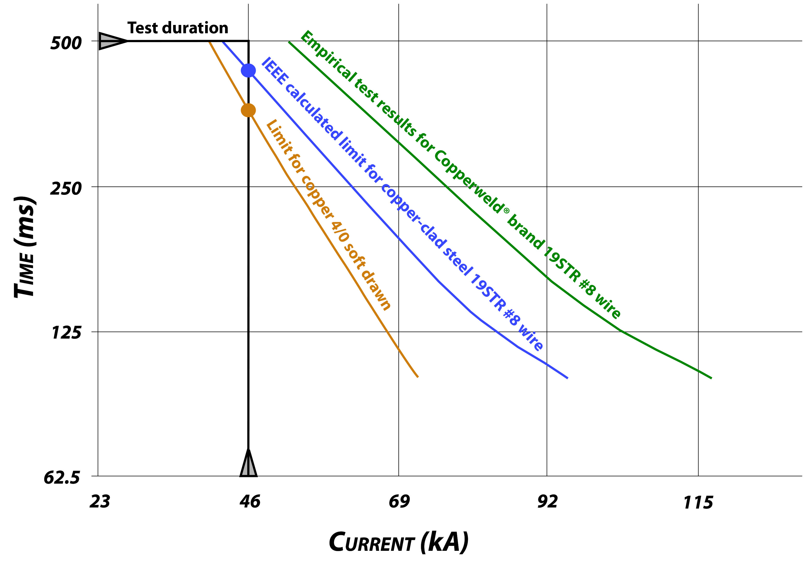
As indicated in the graph in Figure 1, both test articles (conductors) were predicted to fail at the point of the orange and blue dots that represent their fusing limits. The predictions were based on IEEE Standard 80 formulas and tables for both pure copper and copperweld wires. Specifically, Table 6 of IEEE Standard 80 predicted pure copper 4/0 AWG soft drawn would fail at 40 kA, and the formula predicted that 19STR #8 copperweld would fail at 42 kA, when subjected to a 500 ms test.
Interestingly, the manufacturer published the historical fuse-resistance value at 52 kA when subjected to a 500 ms test. This value has been questioned in recent years, given the significant delta from the standard. However, the manufacturer’s literature predicted that the copperweld would not fuse during the test. Only an empirical test, as shown in Figure 1, could resolve the matter.
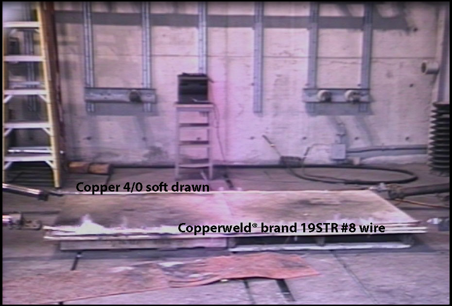
At the initiation of the test, the jacketed copperweld conductor began to smoke, as shown in Figure 2.
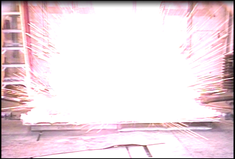
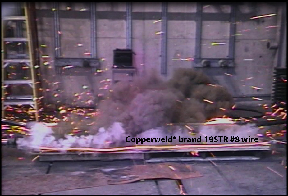
Later, at some time during the simulated 500 ms, 46 kA fault, the 4/0 copper soft-drawn failed spectacularly in an explosion, as shown in Figure 3.
At the end of the test, as shown in Figure 4, the copperweld conductor remained intact, as predicted by the manufacturer’s literature, and not the IEEE STD 80 formula.
Conclusions
The test results indicate that copperweld can, in fact, be engineered to outperform standard copper conductors for today’s transmission and substation grounding applications. The highly specialized process of welding copper to steel is a significant improvement over traditional cladding and plating processes, which may be reflected the IEEE predicted values.
Dollar-for-dollar, copperweld steel-core conductors offer the same strength, wind fatigue-resistance, and theft-deterrence as traditional copper-clad steel conductors more economically, and in addition, offer superior fusing resistance against short-circuit threats.