During an electrical inspection, it can be easy for an authority having jurisdiction (AHJ) to identify a problem or area of further examination if something just doesn’t look right. It can often be identified and cited with a little research and a reference to the National Electrical Code (NEC) or a standard.
The usual issues can range from installation quality (workmanship, workspace, etc.), installation, instruction compliance, or nonconformance with a change in the Code that has been recently adopted. A sharp AHJ will even go a step beyond and focus on compliance with the applicable sections of the NEC that the installation falls under. But what about all of the other potential issues that lay beneath the surface? This can include that shiny green ground screw on an outdoor lug, cable ties supporting conductors below PV modules, or even the custom-engraved placard with a location map on the outdoor disconnect switch to an interactive system. There is no doubt that these would all look nice at the time of installation and subsequent inspection.
Although we at least try to keep up with the changes made in each Code cycle and stay in tune with the latest technology, it is just as important to also pause and take a look back. One major factor that is often overlooked is how our wiring methods hold up to the environment in which they are installed. There are several electrical components or “accessories” that we install (or inspect) and may not think twice about. These can range from various connectors, clips, cable ties, lugs, bushings, or other fittings. They are the parts that are present on every electrical installation but rarely get attention when we learn about the changes of the next Code cycle. And why should they? For the most part, nothing has changed with these accessories, right? As you may have read in previous editions of IAEI News, the quantity of outdoor electrical installations is increasing as the market is adapting to new technology, and PV installations are leading the pack.
THE EVOLUTION OF PV CODES AND STANDARDS
By now, we’ve all had the opportunity to experience a PV system, whether installing, inspecting, encountering alongside other electrical work, or perhaps a friendly knock on the door or phone call. The PV market has significantly increased over the past decade and continues to be strong, according to the Solar Energy Industries Association (SEIA). It has been quite the journey, and we’ve all learned many lessons along the way. For example, take a look at the evolution of PV since the 1999 edition of the NEC where Article 690 was a mere eight pages. This includes less than half a page for Stand-Alone Systems in Section 690.10. Section 690.64 Point of Connection, at the time, was only half a page. This former section (now merged with Article 705 since the 2011 NEC) outlined the most basic requirements: supplyside connections with a reference to Article 230, and a very restricted load-side connection that only allowed the “120 percent rule” by exception for a dwelling unit.
Fast-forward to the 2017 NEC where Article 690 spans across 11 pages, and several sections have since become new articles or have been merged with others. This includes Article 691 Large-Scale Photovoltaic (PV) Electric Power Production Facility, Article 706 Energy Storage Systems, Article 710 Stand-Alone Systems, and Article 712 Direct Current Microgrids. Article 705 has also doubled in size since the 1999 edition.
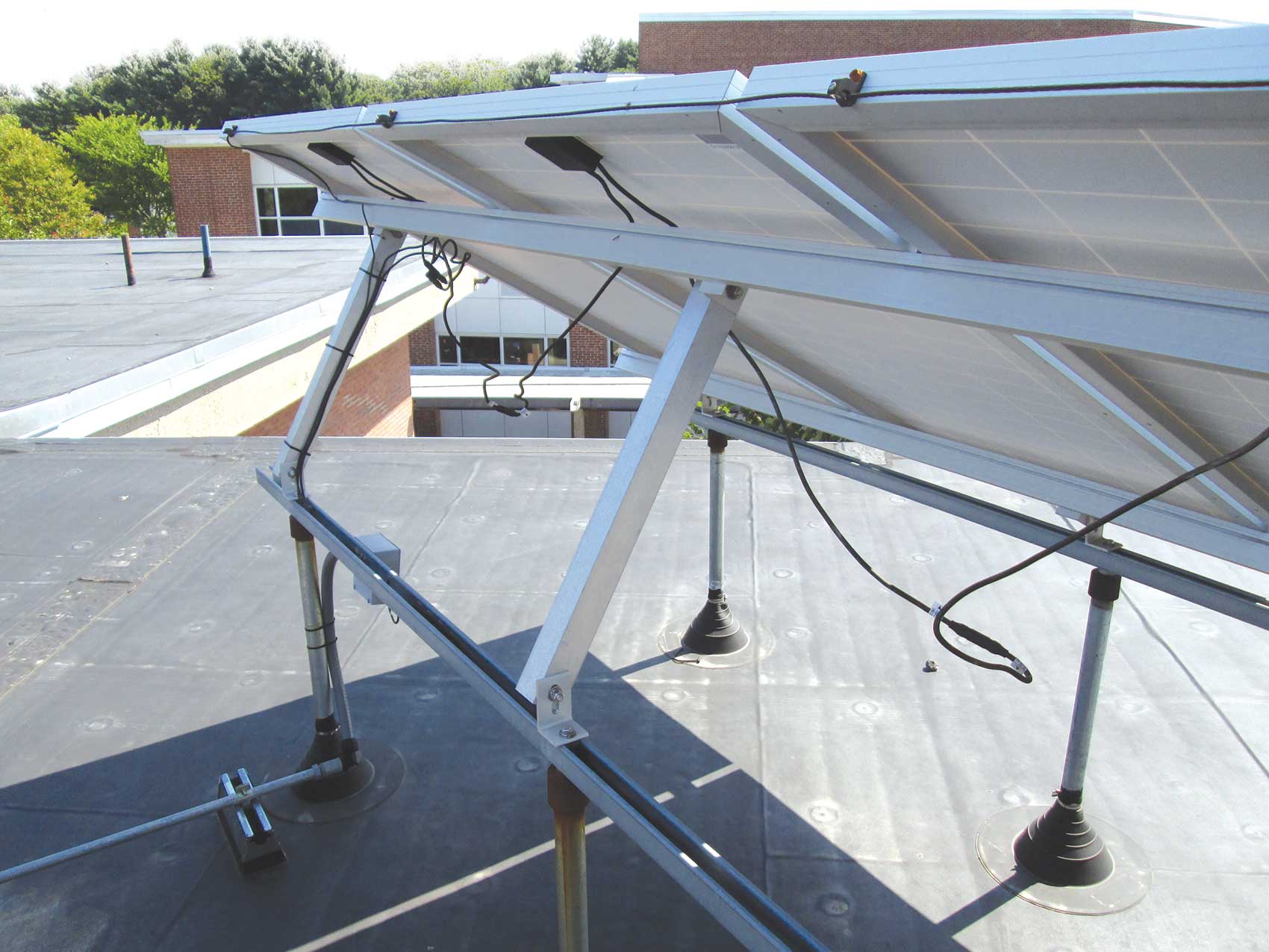
The PV array is perhaps the most exposed portion to harsh environments—whether it be extreme temperatures, UV, rain, snow, ice, and various forms of physical damage. As electricians, we are taught early in our careers that our primary goal is to “protect the conductors.” This is often achieved in several ways. The protection may be from overcurrent, physical damage, or the environment. Modules and racking will be certified to various standards such as UL 1703 and UL 2703, including consideration for this type of environment. Beyond these components, we must consider everything else installed at the array area.
Cable Ties
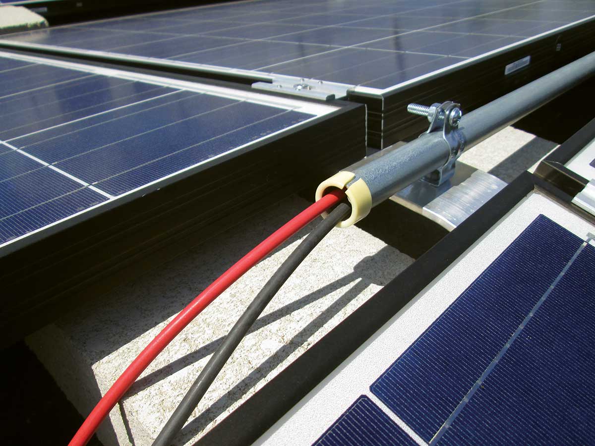
While plastic cable ties seem to be a popular method to support the array conductors to comply with Section 690.31(C), we may learn the hard way they are not all the same. Obvious factors may include UV-resistance and temperature ratings, but is this sufficient? When we look at various types of cable ties, we learn that there are those intended to group or position cables and others to physically support them. The two most common types are Type 21 for positioning and Type 21S for supporting. UL 62275 Cable Ties for Electrical Installations outlines the full set of type classifications.
It is nearly impossible to determine the type just by looking at the cable tie itself, but after several years on an array (or broken on the surface below it), we may have a better idea of what it may or may not be. Some cable ties are certified by a Nationally Recognized Testing Laboratory (NRTL). The certification process will evaluate the cable tie in specific environmental conditions, as well as other factors to determine if it meets the standard for the specific type. Like other electrical products, an AHJ is offered a greater level of confidence with products certified by an NRTL. The installer can also have increased peace of mind with the products they are installing.
Conductor Protection
Many of us may have unfortunately learned the hard way about installing cable ties, but the good news is that manufacturers in the solar industry have not only observed these concerns but continue to offer innovative solutions to address them. This will include means for array wire management integrated into the racking, clips specifically designed (and sometimes certified) to support the array conductors, as well as products to enclose, support, and/or protect the conductors. Sometimes short sections of raceways are used to provide additional support or protection, but once again, it is important to ensure that every component is suitable for the environment and application.
For indoor locations, it is common to see polyethylene bushings protecting the end of electrical metallic tubing (EMT) where conductors or cables exit. When this method is utilized in an outdoor location, not only will it likely violate the bushing’s listing, but it will also likely fail prematurely as we see in photo 1. A popular alternative in the solar industry is by means of a bonding busing. We learned in previous issues of IAEI News that the bonding bushing must also be suitable for the environment, and photo 2 reminds us that replacing just the lug probably won’t hold up. By doing so, we’ve also just modified a Listed (Certified) product.
Conductor Protection
Although the general requirements to ground array components (Section 690.43) haven’t significantly changed over the past decade, our methods have, especially with the introduction of UL 2703 Standard for Mounting Systems, Mounting Devices, Clamping/Retention Devices, and Ground Lugs for Use with Flat-Plate Photovoltaic Modules and Panels.
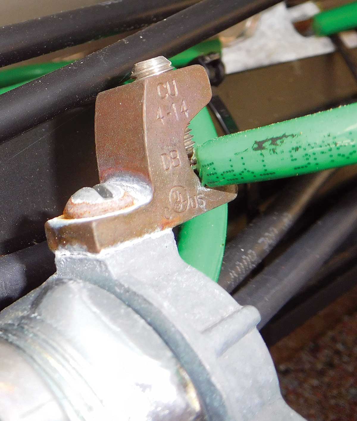
Prior to this Standard, it was common practice to install ground lugs on each module and section of racking. We would often observe a variety of lugs and hardware utilized and not think twice about it. The test of time has quickly identified these lugs that were not suitable for the application—whether it be due to the environment or between dissimilar metals. Not only were the lugs a concern, but also the bolt or screw, and other hardware used to mount the lug, as we see in photo 3. As our methods evolved over the past decade, we significantly reduced the quantity of lugs and focused on the other hardware used to bond modules. At this point, any remaining lugs would likely be critical to the continuity of the grounding method because this location would often be the transition point from the equipment grounding conductor to the equipment that contained integrated bonding components. A failure of this single point could jeopardize the array’s entire ground path.
WIRING METHODS
When conductors leave the array area, we quickly shift gears to NEC Chapter 3 Wiring Methods and Materials. Although many of these components (such as raceways and their associated fittings) rarely change over time, they may be installed in locations that will now challenge their ratings. For example, have you ever observed an EMT raceway as the wiring method on a flat roof? What was the condition of the supports and connectors? What type of damage did you observe, if any? Now, how can that be avoided on a future installation?
The maximum distance between supports for type EMT is 3 meters (10 feet), and within 900 mm (3 feet) of its termination point as outlined in Section 358.30. Depending on the installation, more supports may be necessary to help ensure our wiring method will last the intended life of the system. Furthermore, we may even question whether this type of raceway is suitable for the application. Will it be in an area that is exposed to physical damage, say from other contractors that will need to step over the raceway to access other rooftop equipment?
While this may or may not be considered “severe” physical damage as noted in Section 358.12(1), if other raceways in the area show signs of physical damage, the answer may be obvious. Perhaps provisions to protect the raceway in specific areas may be necessary to reduce the threat of future damage.
For nearly two decades, we have also focused more on the connectors and couplings used on EMT in these locations. UL’s product category FKAV, Electrical Metallic Tubing (EMT) Fittings, outlines requirements for these fittings in wet locations to be “raintight.” To this day, we occasionally observe improper fittings in this environment, and depending on the installation size, the remediation efforts may be enormous.
FIELD-APPLIED MARKINGS
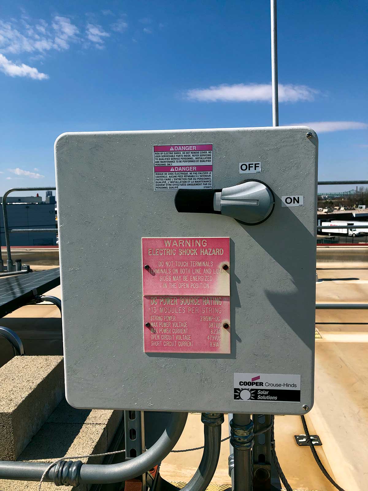
Another increasingly common element to an outdoor installation are the field-applied markings. PV system labeling in the NEC is often a hot topic with its ever-evolving content changes each Code cycle. However, it wasn’t until the 2014 NEC where section 110.21(B) was expanded to help enforce and clarify that labels “shall be of sufficient durability to withstand the environment involved.” After carefully analyzing this section along with the several labeling requirements in Articles 690 and 705, we can see that the type or material of the label is not specified. This is consistent with the purpose of the NEC according to Section 90.1(A) because the Code “is not intended as a design specification ….”
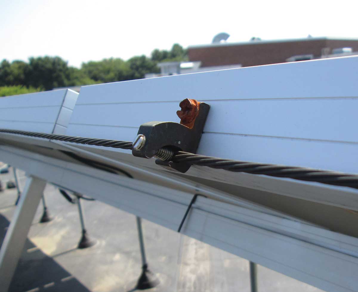
Many of us have the false impression that an engraved placard is always superior to a vinyl label, but once again, the test of time may prove otherwise as we observe in Photo 4. Like the cable tie example, it is nearly impossible to determine if a good-looking, field-applied label is suitable for the environment without further evidence. For an AHJ, the evidence may be from packaging, specification documentation, or sometimes identification right on the label. For the installer, the peace of mind can be established when that installation from several years ago is revisited and the labels are surviving the effects of Mother Nature.
As the solar industry continues to evolve and perhaps mature, we are beginning to learn from our past mistakes, and they are helping us ensure better quality today and in the future. We see this through the substantiation for various public inputs toward the next edition of the NEC, and also by observing existing installations — whether they are our own or constructed by others.
Many electricians who perform preventative maintenance or respond to PV service calls can share their first-hand experience with the premature points of failure. It is critical that this information be circled back to those who design or install systems.
As an AHJ, our continuing education and focus should not be limited to the latest products and codes, but also incorporate environmental effects based on the first-hand experience through observations of existing aged outdoor PV or other installations.
We should take a step back and consider how other parties such as firefighters or maintenance personnel will interact with or stand clear of the installation. Do the maintenance personnel have the appropriate access when servicing nearby equipment? Will firefighters understand the labeling in the event of an emergency? Learning from these experiences will make us all better at what we do and may even make the next installation a bit safer than the last one.