
Our energy-intensive society has developed over the last 150 years using readily available fossil fuels that came from decayed plant matter produced through the process of photosynthesis many thousands of years ago. Those fossil fuels are being depleted and are becoming increasingly more expensive to extract, process, and use. Our society of the future will, in large part, be based on abundant renewable energy in the form of sunlight. Photovoltaic (PV) systems will allow us to effectively and efficiently use the abundant sunlight that we receive each day, and new and exciting improvements in the PV modules and PV systems are occurring each day.
Recent interest has revolved around utility interconnection, including supply-side connections, due to increasingly larger PV systems, energy storage systems and the newest utility interface requirements of ride through, voltage support, frequency support, and power factor control. However, we should not ignore the fact that the electrical energy from the sun originates at the PV module. Installing PV modules in a safe and Code-compliant manner will ensure the longevity and reliability of the system and provide safe, clean, low-cost energy for the foreseeable future.
Let’s look at some of the National Electrical Code (NEC) requirements associated with getting the PV modules properly installed and connected. Mounting and grounding requirements will be addressed, as well as the basic requirements associated with the safety of the PV array and its associated wiring.
Mounting
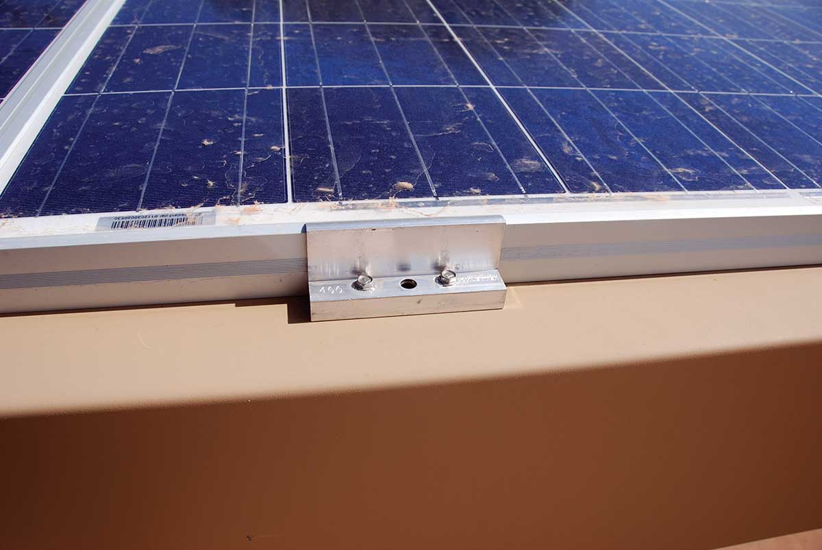
The NEC does not specifically require any particular PV array or module mounting method. Section 110.12 requires good workmanship (undefined), and Section 110.3(B) requires that any listed product be installed in accordance with instructions provided with the product. The module instruction manual will indicate the general requirements for mounting the module. These will include the use of four or more predrilled holes in the back of the module frame. The manual may also indicate that the module may be attached in specified locations with some sort of a clamping device that will attach the module to a racking system (see photo 1.)
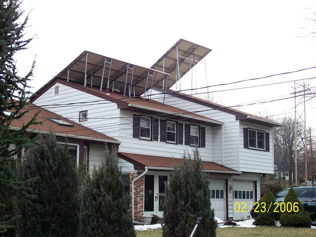
Article 690 does not require the use of listed racking systems although there are numerous racking systems now available that are listed to Underwriters Laboratories (UL) Standard 2703. This standard may be used to list a racking system for module mounting and/or module grounding. Most racking systems are listed for both module mounting and module grounding. However, to use a rack with a particular PV module, the module instructions and/or the rack instructions must indicate compatibility between the module and the rack. This is required because module frame construction varies considerably and not all module frames are suitable for use with the clamping devices available with various racking systems. Listing of the racking system does not cover the connection to the underlying mounting surface or the roofing structure, nor does it make any assessment of the structural integrity of the mounting surface or internal building structure. PV arrays mounted on racking systems attached to roofs exert various concentrated forces on the underlying roofing structure, and those forces may be derived from wind loading, both positive and negative, and downward snow loading. Applicable building codes should be followed (see photo 2).
Where the modules are mounted to another type of structure, or directly to the roof, an assessment must be made to ensure that the instructions provided with the module for mounting to such surfaces are followed and that the structure is rigid enough to meet the module mounting requirements.
Grounding
Most PV modules are constructed with aluminum frames which must be grounded. The module instruction manuals will show the locations where grounding connections may be made where separate equipment grounding conductors are used for grounding. Where individual equipment grounding conductors are attached to each module, they must be attached at one or more of the marked grounding locations on the module frame using either hardware supplied by the module manufacturer (rarely) or with a listed electrical grounding device that is compatible with the conductor being used and the aluminum module frame (see photo 3). In some cases, grounding clamps may be specified in the manual as a method to ground the module to a listed racking assembly which then serves as the equipment grounding conductor for the modules. More commonly, the mounting clamps may serve the dual purpose of mounting and bonding/grounding the PV module to the racking system.
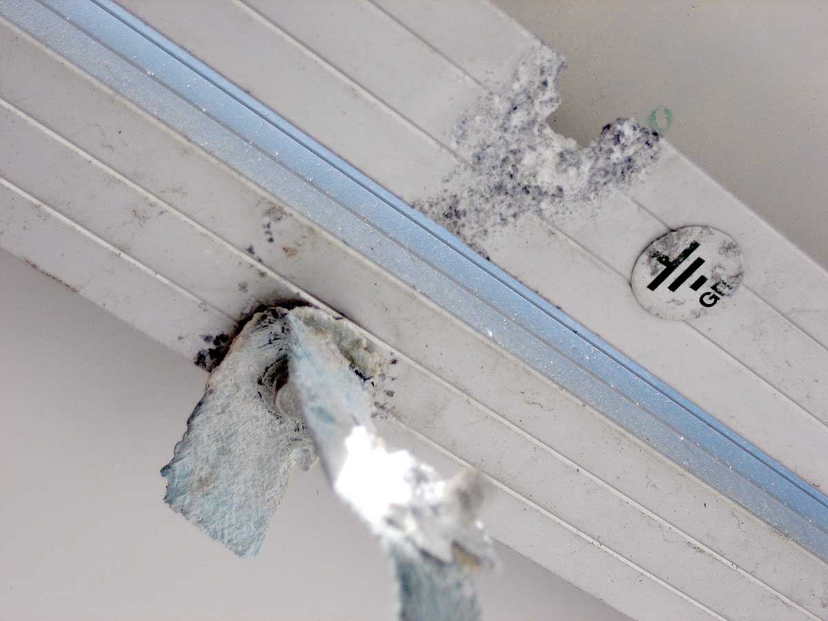
Photo 3. Incompatible materials and methods result in a failed equipment grounding conductor connection. Photo by John Wiles.
In general, the Code requirement to run equipment grounding conductors with circuit conductors also applies to PV module circuits to ensure proper operation of overcurrent devices in the DC circuits. For this reason, as soon as the PV DC or AC PV module output circuits leave the PV array, the equipment grounding conductors should be routed in the same raceway as the circuit conductors. Equipment grounding conductor size is based on the overcurrent device protecting the module circuit or the output of the DC combiner (no smaller than 14 AWG) except where the equipment grounding conductors are exposed to physical damage, and then they should be no smaller than 6 AWG (690.45).
PV rapid shutdown system
The evolving PV rapid shutdown system (PVRSS) requirements found in Section 690.12 address first responder safety with respect to DC and AC PV circuits on or in a building that may remain energized when the main AC power to the building is disconnected during an emergency. In the 2017 NEC, an array boundary for PV arrays mounted on buildings is defined as a distance of 305 mm (1 foot) from the outside edge of the array. Conductors on or in the building outside of this boundary must be controlled to no more than 30 V (conductor to conductor and conductor to ground) within 30 seconds of PVRSS initiation. Effective January 1, 2019, conductors within the array boundary must be controlled within 30 seconds of PVRSS initiation to no more than 80 volts.
On DC string inverter systems, both the array output voltages, and any residual DC voltages on the PV DC output conductors that may originate from the inverter input filter capacitors must be controlled. These requirements will usually dictate that the inverter be listed as PVRS equipment (PVRSE) or that a device be mounted at the inverter to deal with the inverter DC voltages. Another device (or devices) will be mounted at the PV array boundary. In some cases, DC-to-DC converters located at the modules work in conjunction with a compatible string inverter that is listed as PVRSE and the combination, when initiated, shuts down the required controlled conductors.
A new UL Standard 3741 is being developed that will address the certification and listing for an entire PV array that is inherently safe and will provide hazard control for first responders.
AC PV modules—and modules with microinverters attached to each module—provide a PVRSS that controls conductors both inside and outside the array boundary (these are all AC conductors) when the PVRSS is initiated.
Section 690.12(C) lists several possible initiation devices. For one- and two-family dwellings, that device must be located in a readily accessible location on the outside of the dwelling. Proposed changes for the 2020 NEC will require an AC utility power outdoor emergency disconnect in a readily accessible location. This will integrate nicely with the PVRSS initiator location requirement.
Section 690.56(C) identifies the extensive labeling required for a building with a PVRSS. In all PVRSS installations, the authority having jurisdiction (AHJ) should have the PV system installer demonstrate the proper operation of the PVRSS and show that all controlled conductors are indeed controlled upon initiation of the system.
Arc-fault detection
PV systems installed on or in buildings that have a voltage of 80 V DC or greater between conductors (or conductors to ground) are required to have an arc-fault detection and interruption system (690.11). Ground mounted arrays and PV DC circuits in metal raceways are excluded. This system will usually be included in the Certified (Listed) and Marked inverters. However, on larger systems they may also be located in the combiner boxes near the PV array. Manufacturers’ product literature and markings on the products should indicate the presence of these Listed devices or the internal capability of various pieces of equipment. There should be a method by which the operation of them can be verified. The AHJ should have the installer verify the operation of these arc-fault detection systems according to the manual instructions.
Voltage ratings
The number of modules in series, the lowest expected ambient temperature, and the open-circuit voltage-temperature characteristics of the module should be used to determine the maximum system voltage as required by Section 690.7. This maximum system DC voltage should not be greater than the maximum rated voltage of the conductors, the inverter input, any DC disconnects, DC combiners, and any DC overcurrent devices. Where DC-to-DC converters are used, their rated output voltage is used to determine the maximum system voltage. Where DC-to-DC converters are connected in series, the string inverter may affect or control the string voltage [Section 690.7(B)]. The PV installer and the AHJ should have an agreement on the lowest expected temperature at the installation location, and the installer should include all voltage calculations in the permit application.
Conductor size/type
The conductor size in the PV source and PV output circuits is generally determined by the maximum current, which is defined as 125 percent of the module short-circuit current and the number of modules or strings of modules in parallel (Section 690.8). Where DC-to-DC converters are involved, the rated continuous output current of the DC-to-DC converter shall be used as the maximum current [Section 690.8(A)(6)].
After determining the maximum current, the conductor ampacity is determined by either 125 percent of the maximum current before the application of any adjustment factors or by using the adjustment or correction factors on the maximum current without any additional 125 percent factor [Section 690.8(B)].
Both USE-2 and PV Wire/Cable may be used for exposed DC PV circuit conductors on both grounded and ungrounded PV arrays (the definition of which will be covered in a subsequent article).
Overcurrent protection
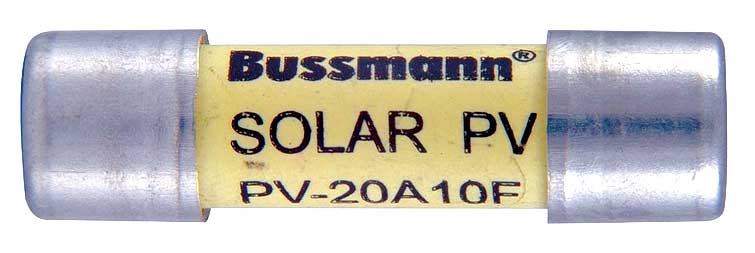
In general, overcurrent devices protecting DC source circuits and DC output circuits shall be sized at 125 percent of the rated short-circuit currents in those circuits. See Section 690.9 for variations and exceptions to this basic requirement. The voltage rating of any overcurrent device shall be greater than the maximum system voltage in that circuit. All DC overcurrent devices in the DC PV circuit shall be Certified and Listed for the PV application (see photo 4.)
Disconnects
Sections 690.13 and 690.15 establish the requirements for disconnects in the DC circuits of a PV system. In the 2017 NEC, there is no specific disconnect requirement for the DC conductors at the point they enter a building or structure. This previous requirement has been superseded by the PVRSS requirements that establish the safety of these conductors on or in a building.
However, there is a requirement for a DC disconnect/isolating device at the array location to provide equipment isolation for the PV modules (Section 690.15), but it has been proposed that this requirement be eliminated in the 2020 NEC. See Section 690.13 for requirements for the PV system disconnect, which may be in the DC circuits or the AC circuits depending on system configuration.
Isolating devices must be provided for PV modules, AC PV modules, fuses, DC combiners, DC-to-DC converters, inverters, and charge controllers. A connector may be used in some cases as an isolating device, but at the higher currents a disconnect (switch or circuit breaker) must be used (Section 690.15).
This brief outline of Code requirements for the PV module and the PV array indicate that focused, detailed compliance with these requirements will help to ensure a safe, durable, and reliable PV system that will continue to produce electricity from sunlight for decades—probably far longer than the 25-year warranty on the PV modules.