For the time being, the transmission of electrical energy in a photovoltaic (PV) electrical power system requires that the various components be hardwired. Followers of Nikolai Tesla may, at some point in the not-too-distant future, develop means of transmitting energy at high levels wirelessly. I, for one, would not want to be in the space through which wireless power at significant levels is being transmitted. I am surrounded enough by large amounts of “electro smog” from cell phones, cordless phones, and Wi-Fi. I do not wish to live in a microwave oven.
This article will discuss the conductors that are used to carry PV energy, the PV currents that those conductors will be carrying, and protection of those circuits and conductors from excessive currents.
Conductors. A conductor is a material, usually (but not always) metallic, that can carry electrical current.
While the National Electrical Code does not define “conductor” per se, it does have definitions for a “bare conductor” (a conductor with no covering or insulation); for a “covered conductor” (a conductor with a covering that is not recognized as insulation); and for an “insulated conductor” (a conductor encased in a material that is recognized by the NEC as electrical insulation.
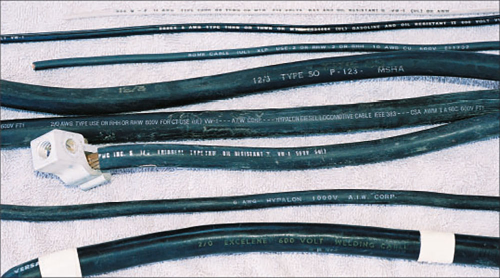
Conductors come in many different shapes and configurations. They may be a solid circular shape; they may be rectangular like busbars; or they may be stranded with multiple solid circular or noncircular individual conductors. In this article, when the term “conductor” is used, it will be referring to an insulated conductor unless otherwise specified. In order to qualify as an insulated conductor in the NEC, the conductor must pass the rigorous requirements of UL standards. Some of the acceptable cable types are shown in NEC Chapter 3 and others are described in Table 400.4. (See Photo 1.)
The word “cable” is sometimes used interchangeably with the word “conductor.” Throughout the Code, the word “cable” is used but is not explicitly defined as a distinct device. The Code has definitions for coaxial cable, fiber-optic cable (nonmetallic), communication cables, data cables, and many more. Cables usually are composed of more than one conductor, although there is some trend towards specifying larger size conductors as cables, such as a 4/0 AWG battery cable (706.32) or a 2/0 AWG welding cable (630.41). And, of course, the PV industry has to be different in that they have PV circuits connected with single-conductor cables [200.6(6); 690.31(C)]. For the most part, these single-conductor cables are just like insulated conductors.
An example of a cable is a Type SE cable, which has an outer covering that is not considered to be an insulator, but provides some mechanical protection for the internal insulated phase or “hot” conductors and the bare conductor serving as the equipment grounding conductor or neutral.
Conductors come in various sizes and are specified as AWG (American Wire Gauge) or in thousands of circular mills (kcmil) for the larger sizes. The cable size determines the ability of the cable to carry currents. Cables come with various voltage ratings, such as 600 V, 1000 V, 2000 V, and higher, and these voltage ratings are dependent on the thickness and type of insulation that the conductor has.
The metallic element of the power conductors used in typical residential, commercial, and industrial power systems is typically made of copper, aluminum, or copper-clad aluminum. The electrical resistance of each of these materials varies and will affect the current-carrying capacity (ampacity) of the conductor. In other industries, metals such as silver and gold have been used to carry electrical energy, but their cost precludes their use in residential or commercial electrical power systems. New materials are being developed that have far lower resistances and lower losses than the materials used today. These superconductors will allow very large amounts of energy to be transmitted over large distances with very low losses.
Currents. The output of a PV module is direct current (DC). This current flows in one direction only when the module is producing power. Other DC circuits in a PV system may involve energy storage systems such as batteries. DC currents may range from a few amps at the individual module output to hundreds of amps at the output of DC PV combiners and up to thousands of amps at the input of large utility scale central inverters.
The output of PV inverters is alternating current (AC). This applies to both utility-interactive inverters and standalone inverters. The AC is typically 60 Hz in North America and goes through sixty full positive and negative cycles per second as the current reverses each half cycle. The current waveform is usually a smooth sinusoidal wave. However, early standalone inverters had a modified sine wave or modified square wave output, which (while providing some utility for powering AC loads) had problems with numerous types of utilization equipment having solid state circuits. The inverter AC output may have nominal voltages of 120 V, 208 V, 480 V, and higher for larger, utility-scale systems.
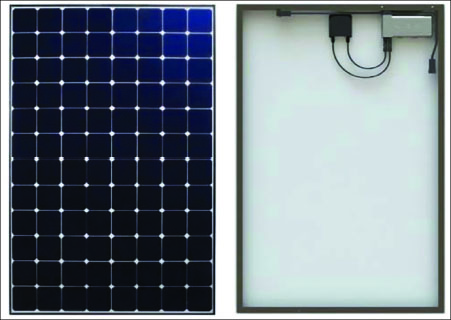
Alternating current PV modules are a combination of a DC PV module and a microinverter integrated with the module that are listed as a single device with an AC output (690.2; 690.6). (See photo 2.) Power levels of these devices range from about 100 watts to more than 300 watts. The DC requirements in the Code do not apply to the DC circuits in an AC module because they are part of a listed device. Microinverters as standalone devices, on the other hand, must meet both AC and DC Code requirements where the listing of the device does not cover those requirements.
The vast majority of PV systems being installed today are utility-interactive, which means they are connected to the utility power system. They may or may not have energy storage systems associated with the on-site PV system.
These systems require the utility connection, and they also require that the utility be present and operational within tight limits of voltage and frequency. However, when energy storage is involved, the system may provide energy to local AC loads when the utility grid is not present. A few systems can provide limited amounts of energy from the PV system to supply local AC loads during the daytime when the utility is not present, even though they do not have an energy storage system.
There have been, and will continue to be, off-grid PV systems that are not connected to the utility grid that may have AC outputs or may be designed to provide only DC outputs (or some combination of both). An off-grid PV system is not exempt from the requirements of the NEC where that Code has been enacted by the local jurisdiction.
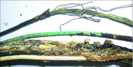
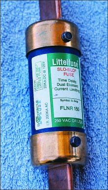
Overcurrent protection. Conductor size is selected for a particular circuit based on the current the conductor must handle, the conductor ampacity rating, and the tradeoff between costs of the larger conductor and the lower losses in the larger conductor. Under normal operating conditions, the conductor is sized to operate within its design parameters as established by various Code tables for specific conductors. However, faults in electric circuits do occur, and in numerous circuit configurations the conductors may be subjected to currents far in excess of their design parameters. This necessitates the installation of overcurrent protection for many conductors in the electrical power system, particularly those that may be subjected to overcurrents under fault conditions. (See photo 3.)
Unrestrained overload currents or fault currents in a conductor will cause heating of the conductor, insulation failure due to the heating, and possibly fires.
The resistance of a conductor and the current through a conductor determine the heating in the conductor. That heating, expressed as watts, is shown by the equation:
W = I x I x R
(Where W is watts, I is current, and R is the resistance of the conductor.)
Fortunately, we do not have to deal with this equation because the Code gives us various tables showing the maximum current that each conductor can carry, and various deratings of that current based on environmental conditions (such as the number of conductors bundled together or in conduit and the ambient temperature that these conduits or conductors are exposed to). When there is a potential for a source of currents that exceeds the ampacity rating of the conductor, that conductor must be protected by an overcurrent device in most cases.
AC is easy, DC is harder. Consider the sinusoidal waveform on an AC current. That current goes through zero 120 times per second on a 60-Hz current, and when the current waveform goes through zero, the current is essentially zero. Now, when a switch, circuit breaker, or fuse on an AC circuit must open due to a manual operation or an overload condition, there is a tiny arc formed between the switch/breaker/fuse contacts as the device goes from a closed position to a fully open position. Of course, the fuse has elements that melt, but the arc in the fuse is somewhat similar to the arc when the switch contacts open in a switch or a circuit breaker. The higher the current, the larger the arc. The energy in the arc is proportional to the current and the time the arc exists and can be expressed by the equation:
E = I x I x t
(Where E is the energy, I is the current, and t represents the time that the arc exists.)
The energy released tends to degrade and sometimes destroy the contacts on switches and circuit breakers and possibly destroy the fuse housing if allowed to exist for very long periods (where “long” means milliseconds). However, AC-rated switches, circuit breakers, and fuses have a relatively easy job of interrupting the current and extinguishing the arc. Note that the AC current goes to zero 120 times per second. When the current goes to zero, the arc starts to extinguish itself or be extinguished. The arc, during the period of time it takes the switch to open or the fuse to melt, may be extinguished several times and, as a result, the energy released is substantially reduced. This makes the design and construction of AC-rated devices fairly straight forward.
Consider, on the other hand, the DC arc, which is continuous and does not extinguish itself 120 times a second. The arc is continuous and generates considerably more heat than a similar AC arc, which can be detrimental to switch contacts, breaker contacts, and the durability of the fuse body. For this reason, the design of DC-rated circuit breakers, switches, and fuses is considerably more difficult than the design of their AC counterparts. They must be designed mechanically and thermally so that the period of time between a closed contact and a fully open contact is much shorter than the equivalent time on an AC switch, breaker, or fuse. Some may recall the older AC “snap” switches which may have also had a DC rating.
Although some devices (disconnects and overcurrent devices) have dual AC and DC ratings (see photo 4), an AC-only rated device should never be used in a DC circuit because it may fail the first time it is used, or it may fail at some later date. The use of an AC-only rated device in a DC circuit violates Article 110.3(B) of the Code and is a significant safety hazard. Additionally, overcurrent devices listed for marine or automotive applications should not be used in electrical power installations falling under the NEC.
Overcurrent Protection in DC PV Circuits. The 2017 NEC requires that overcurrent devices used in DC PV circuits be listed for the PV application. This is primarily due to the environmental conditions to which these devices may be subjected in PV DC combiner boxes and other PV circuits [690.9(B)]. The Standard (UL 248-19) requires that these devices are listed to address these environmental conditions and ensure that, when properly installed according to the manufacturer’s instructions, the overcurrent device will work as designed. One area that needs continuing attention is the internal temperature of PV DC combiners when they are exposed to sunlight on rooftops.
Where there are no external sources of overcurrents that can damage a conductor, and where all sources of short-circuit currents do not exceed the ampacity of the conductor, then no overcurrent protection is required [690.9(A) EX].
Another change in the 2017 Code involves functional grounded systems where both circuit conductors will be ungrounded, but only a single overcurrent device is permitted in one of the two ungrounded conductors. However, if this option is selected, then any other overcurrent device in the same DC circuits or downstream in PV DC combiners must also be in conductors of the same polarity [690.9(C)]. This is a significant change from previous NEC requirements, which required overcurrent protection in both of the ungrounded circuit conductors. The change is largely due to the more universal application of ground fault detection and interruption requirements.
Because many of the devices used in PV systems are current sources (the PV module) or are current-limited (inverters, micro inverters, and DC-to-DC converters), care must be exercised when locating the overcurrent device to protect conductors when a source with a higher available current is also connected to the same circuit. The overcurrent device must still be selected based on the desired current and conductor size, and it should be located at the highest source end of the circuit [690.9(A)]. At some point, the Code will say that when a conductor has sources at each end that have appropriately rated overcurrent devices, the conductor shall have an ampacity no less than the rating of the largest source.
Summary. While conductors have remained largely unchanged in recent years, their uses have expanded in NEC requirements. Overcurrent protection is usually required in PV systems and new requirements have been established for the devices and their uses.
John Wiles has retired from the Southwest Technology Development Institute at New Mexico State University but is devoting about 25% of his time to PV activities to stay active in the NEC and UL Standards development process. Seven to eight-hour presentations are still available on PV and the Code and they cover 2011-2017 NEC requirements. He can be reached by e-mail at jwiles@nmsu.edu or by phone at 575-646-6105