Based on the number of queries I get via phone and email, I sometimes think that more than half of the load centers in residences throughout the country consist of center-fed load centers or panelboards. It is not a simple, straightforward procedure to connect PV to these load centers and, as most of you know, the requirements for connecting PV system outputs to center-fed load centers are not covered in editions of the code before the 2014 NEC. Plan reviewers, inspectors, and PV installers should be aware of the various options for dealing with these center-fed load centers today and in the future as the 2014 NEC is adopted in various jurisdictions.
To make it perfectly clear what we are discussing, a center-fed load center or panelboard has a continuous busbar for the load breakers. More precisely, there are two busbars in these load centers, one for Line 1 and one for Line 2 on a 120/240V electrical system. The main breaker from the utility service is connected at the center of this set of busbars. Each busbar is continuous and is not split in any way letting currents flow back and forth depending on the loads and the sources. See photo 1 and photo 2. These center-fed panels may be mounted vertically or in some cases horizontally. In this article, only one busbar will be discussed since each of them in the set of two has its own main breaker pole and is treated individually as far as current calculations are concerned.
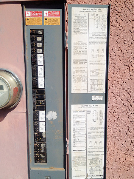
Photo 1. Center-fed Panelboard Courtesy SunSpot Solar
There is also a type of center-fed panel that has double two-pole main breakers at the center and each double-pole main breaker feeds a separate busbar set. This article does not deal with this type of panelboard because it is handled much like an end-fed load center. Another type of center-fed load center also has a double two-pole main breaker, but the breaker poles are connected in parallel and each parallel set feeds a continuous busbar that is not split.
In a normal non-PV installation, the main breaker protects the busbar from overload no matter how high the connected loads are. And, in most load centers the sum of the rating of the installed load breakers (single-pole 120-volt and double-pole 240-volt units) will exceed the rating of the busbar by a significant amount. However, in a normal well-done, code-compliant installation, the main breaker and the branch-circuit breakers should never see more than 80% of their rating in terms of continuous load currents. This is due to the load calculations and the 125% factor required when sizing circuit breakers in Chapter 2 of the Code.
The Potential for Overloading
In a normal, non-PV panelboard or load center installation, as mentioned above, the main breaker will restrict the maximum currents that the busbar can see no matter what loads are imposed through the load breakers for each branch circuit or feeder. However, when an additional source is added to the busbar in the form of a backfed PV breaker there are now two sources of current and the potential exists to overload the busbar. Note in figure 1 that there is a possibility of current from the main breaker and current from the backfed PV breaker to add together and potentially provide high currents above the busbar rating to the upper half of the busbar that is opposite the location of the backfed PV breaker. Of course, this situation can only exist as a function of the load currents and when the PV source is present. If the half of the busbar containing the PV output has loads that will absorb most, if not all, of the PV output current, then it is unlikely that the other half of the busbar will be overloaded. Unfortunately, we cannot directly control how load currents exist in a given building or structure, and at times the load currents on the half of the busbar where the PV backfed breaker is located may be near zero and the full available PV output current can add with the current from the main breaker to overload the busbar on the opposite half away from the PV breaker.
Because of this potential overload, it is not possible to apply the 120% rule in NEC Section 705.12(D) to a center-fed panel. And, in fact, this issue is the primary reason why center-fed panels have not been mentioned in editions of the Code before the 2014 NEC. Here are the two applicable sections in 705.12(D) of the 2011 NEC:
(2) Bus or Conductor Rating. The sum of the ampere ratings of overcurrent devices in circuits supplying power to a busbar or conductor shall not exceed 120 percent of the rating of the busbar or conductor.
(7) Inverter Output Connection. Unless the panelboard is rated not less than the sum of the ampere ratings of all overcurrent devices supplying it, a connection in a panelboard shall be positioned at the opposite (load) end from the input feeder location or main circuit location. ……
The language in (7) is tortuous at best. Briefly, the 120% rule in 705.12(D) can be applied only when the PV backfed breaker is mounted at the opposite end of the busbar or conductor from the main utility breaker. Supply sources located at opposite ends of a busbar prevent any place on the busbar from seeing the sum of the two supply currents. If this PV breaker position is possible, then the sum of the utility breaker rating plus the sum of the backfed PV breaker rating can be as great as 120% of the busbar rating. Unfortunately, with a center-fed panelboard, this location of the backfed PV breaker with respect to the main breaker is not possible. There will always be the potential for overloading the half of the busbar that the PV breaker is not installed in.
When the location of the backfed PV breaker to meet the 120% rule is not possible, the 100% rule must be applied and the sum of the main utility breaker rating plus the sum of the backfed PV breaker rating may not exceed 100% of the busbar rating. See the “Perspectives on PV” article in the January–February 2013 issue of the IAEI News for more details on load-side connections.
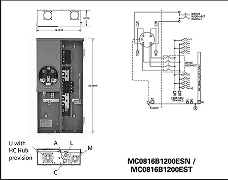
Photo 2. Center-fed Load Center with schematic Courtesy Siemens
Options before the 2014 NEC Has Been Adopted
Oversized Busbar. In many center-fed (and other) load centers, the main breaker has the same rating as the busbar, and it is not possible to add any backfed PV breaker because of the 100% rule. However, there are some load centers where the bus bar is labeled at a higher rating than the main breaker. For example, some load centers have labels showing 225-amp busbars and only 200-amp main breakers. Other load centers may have labels showing 125-amp busbars with 100-amp main breakers. If the accuracy of these ratings can be verified by the manufacturer, applying the 100% rule in both cases would allow 25 amps backfed PV breakers to be added to the busbar without any potential for overloading provided that PV breaker is located at the end of the busbar.
Lightly Loaded Panelboard with Interchangeable Main Breaker. Some manufacturers of load centers have the center-fed panelboards made with replaceable/interchangeable main breakers. If a full NEC Chapter 2 load assessment were made on the building or structure that is fed by a panelboard, it might be determined that the existing load would allow the replacement of the existing main circuit breaker with a main breaker having a lower rating.
Measurement of the currents and loads at any one particular time or over a short period of time with a watt meter may not reveal the loads that could occur at other points in time. Load assessments should only be done after carefully assessing the potential loads on the building according to the NEC Chapter 2 requirements in a code-compliant manner to establish that an oversized service has been installed. And if the main breaker can be and is reduced, the load center should be carefully placarded to indicate that lower rating of the main breaker and to warn against adding any additional loads or load circuits to the panelboard without a reassessment of all loads.
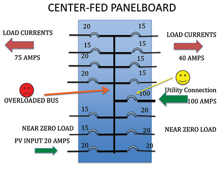
Figure 1. Center-fed busbar showing potential overload
Load Center Replacement. When the two options above are not possible, then it may be necessary to remove the center-fed panelboard and install a new load center with the normal end-fed main breaker. While the latest edition of the NEC does not require updates to existing, installed electrical systems, when an electrical system is modified in any way (e.g., installing a new load center), both the NEC and local codes should be carefully reviewed. Because older panelboard/loadcenter installations may not be safe according to current codes, the national and local codes in all areas relating to the selection, installation, and use of these devices must be reviewed and the installation of the new equpment brought into compliance. Local codes should be reviewed to determine whether or not the breakers in the panelboard would have to be upgraded to GFCI breakers or AFCI breakers.Typically, a simple panelboard change out would not require GFCI or AFCI upgrades without additional modifcation to existing branch circuits, but check with your local authority having jurisdiction just the same. And, with a load center replacement, other portions of the existing electrical system may have to be upgraded to meet current local code requirements such as relocating the existing panelboard or load center location out of the vicinity of easily ignitible materials such as a clothes closet. Yes, load center replacement interrupts the service and adds cost to the PV system, but the requirements for safety should not be compromised by trying to short-cut Code requirements.
Supply-Side Connection. Where the service-entrance conductors and circuits are easily accessed, a supply-side PV connection may be used and NEC Section 705.12(A) allows this type of connection. If the existing center-fed load center is a meter-main breaker combo or a meter-main panel combo, then the mistake should not be made of attempting to do a supply-side connection between the meter socket and the main breaker inside the combo panel. This will generally violate the listing on the center-fed panel and is a violation of NEC Section 110.3(B). See “Perspectives on PV” in the November-December 2013 issue of the IAEI News for more details on supply-side connections.
2014 NEC Requiremnts
The 2014 NEC in Section 705.12(D)(3)(d) specifically addresses the center-fed panel as follows:
(d) Connections shall be permitted on multiple-ampacity busbars or center-fed panelboards where designed under engineering supervision that includes fault studies and busbar load calculations.
The requirement for engineering supervision will generally indicate that a Professional Engineer should accomplish the required studies and calculations. Load calculations will usually involve not only the NEC Chapter 2 load calculations for the building, but how those loads are distributed on each half of the busbar, the potential for adding plug loads on each branch circuit on each half of the busbar up to the breaker limits, and the impact of operating breakers as possibly more than 80% of rating on the thermal stability of the panelboard. The distribution of the loads on the panelboard busbars should lean toward having the heavy loads on the half of the busbar containing the backfed PV breaker, and that PV breaker must be located as far from the main breaker as possible. In most cases, the total ratings of the breakers on the opposite half of the busbar from the PV breaker should total less than the busbar rating.
Fault studieswould look at the available fault current from the service and ensure that the panelboard is rated to handle those fault currents. In some locations, the utility distribution system may have been been upgraded and can deliver greater fault current than the original panelboard was designed for. This would necessitate upgrading the panel and, at this point, an end-fed panel should be considered. Fault studies may also include looking at the impact of fault currents under arcing fault conditions generated by the PV inverter and how these can add to the currents from the utility main breaker and the impact of this condition on the busbar and the load breakers. Although many people think that the inverter will shut down under fault conditions, however if the fault is an arcing fault, the inverter may deliver current up to its rated output current into that fault, particularly when the voltage from the service is not significantly reduced to below the inverter turnoff voltage (88% of nominal) during the arcing fault.
In all cases where an existing center-fed panelboard is being used, any assumptions in existing conditions should be carefully noted. The panelboard should be placarded to indicate that breaker positions should not be changed, additional breakers should not be added, and the addition of plug loads should be minimized. Where possible, it might be good to place blocking devices over vacant breaker locations.
And there will be installations where the required studies and calculations indicate that it is not possible to use the existing center-fed panelboard, and either an end-fed panel board should replace it or a supply-side connection should be used.
Alternate Methods and Materials
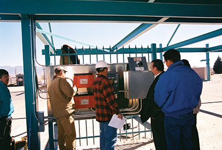
Some jurisdictions have a formal or informal process of modifying NEC requirements to allow electrical installations in a safe manner using alternate methods and materials. See photo 3. Where those alternate methods and materials processes exist on codes prior to the 2014 NEC, the 2014 NEC requirements for studies and calculations under engineering supervision might be applied to center-fed panelboards.

Photo 3. PV Installers and AHJ discussing an Alternate Methods and Materials procedure to meet NEC requirements.
Summary
Center-fed panelboards or load centers are found throughout the country in existing and new electrical installations. There are several ways that PV systems may be connected to the center-fed panelboards and in all cases they can be replaced with an end-fed panelboard for complete compliance with existing codes. The 2014 NEC will allow center-fed panelboards to be used under engineering supervision and these requirements may be applied to earlier codes using the alternate methods and materials
For More Information
The author has retired from the Southwest Technology Development Institute at New Mexico State University, but is devoting about 25% of his time to PV activities in order to keep involved in writing these “Perspectives on PV’ articles in the IAEI News and to stay active in the NEC and UL Standards development. Seven- to eight-hour presentations are still available on PV and the Code and they cover 2008–2014 NEC requirements. He can be reached at: e-mail: jwiles@nmsu.edu, Phone: 575-646-6105
The Southwest Technology Development Institute web site maintains a PV Systems Inspector/Installer Checklist and all copies of the previous “Perspectives on PV” articles for easy downloading. A color copy of the latest version (1.93) of the 150-page, Photovoltaic Power Systems and the 2005 National Electrical Code: Suggested Practices, written by the author, may be downloaded from this web site: http://www.nmsu.edu/~tdi/Photovoltaics/Codes-Stds/Codes-Stds.html