
‘TWAS A BRIGHT AND SUNNY MORNING. Kate was up at her usual time of 0600 to feed the cat and dog and get ready for a week’s worth of work inspecting PV systems. She had cleared most items on her desk last week and looked forward to tackling new projects.
After her morning exercise and a light breakfast, she gathered together her tools of business. Her jurisdiction, which included her supervisor Paul, the building official, emphasized safety with all of the inspectors.
Her daily work shoes were a lightweight pair of ankle height walking shoes which had ANSI rated plastic safety toes and electrical dielectric strength soles. Her hat had a long, wide bill on it and a sun-shield cloth on the back to protect her neck and ears from the intense solar radiation she was exposed to while inspecting PV systems for hours each day. When she was at an active construction site, she wore the hardhat that she kept in her truck, which also had a sun shield cloth on the back. As she left the house, she made a mental note to schedule her annual CPR refresher training and to check on any new training packages on construction industry safety that might be available from OSHA. Training in both of these areas was required by her jurisdiction.
The Process. When she got to work, she met with Ron, the plan reviewer, and discussed some particulars on the systems that she was going to be inspecting that he had already OK’d during the plan reviews.
In her jurisdiction, PV systems usually involved multiple stages of plan review and inspection. After the PV system has been permitted and passed plan review, a two-stage inspection was involved. Prior to connection to the utility, and before the system was turned on, the PV system was subjected to a “rough-in” inspection, where all the mechanical and nonfunctioning electrical systems were inspected for code compliance. The local utility required this inspection prior to making the interconnection. Before making that interconnection, the utility also inspected the interconnection equipment and circuits from the inverter ac output to the utility point of connection.
Ground Fault, Arc Fault, and Rapid Shutdown Equipment Inspections. After the PV system was connected to the utility, the local jurisdiction performed an operational inspection to ensure that the active PV system equipment including ground fault detection/interruption devices (690.41), PV DC arc-fault circuit interrupters (690.11) and any PV rapid shut down equipment (690.12) was working as required.
Although Kate had no specialized equipment to test the ground fault and arc-fault detectors, she did make an effort to ensure that neither of these devices was indicating a problem on the operating PV system. In a few cases, exciting, unanticipated events occurred with these systems when the PV installer had not done their due diligence.
She required that the newly-required PV rapid shutdown system be initiated at each of the multiple initiators (where installed), and the installer would have to show that the Code requirements for control conductors be met with the voltages reduced to 30 V within 30 seconds. In some instances, this meant going on the roof to the dc PV combiner boxes and monitoring the output voltage(s) of those combiners to ensure that they met Code requirements when the rapid shutdown system was activated.
Normally the dc input to each of the string inverters was also monitored unless those inverters were inside the ten-foot array boundary [2014 NEC 690.12(B)]. Kate knew that conductors inside the array boundary were not required to be controlled until January 1, 2019, when 690.12(B)(2) in the 2017 NEC became effective. Moreover, she also knew that Underwriters Laboratories was working on a new standard to address systems that might meet those requirements and that module-level power electronics including some microinverters and dc to dc converters already met those requirements.
Anti-Islanding and Ride Through. She also required the installer to demonstrate that the anti-islanding circuits in the inverter(s) were working properly when the main ac PV system disconnect was opened. Although she was in California, the local utility had not yet adopted any requirements related to the newer utility “ride-through” PV system interconnections. She had been pondering how the new inverters could be tested to ensure they met those ride-through and anti-islanding requirements when they were adopted by the utility and the jurisdiction.
In all cases, Kate required that the installer activate the various disconnects or switches involved with a particular test and provide the metering and operate the test equipment to show that Code compliance had been achieved.
The local utility was pro-PV and worked with the installers to make the electrical interconnection in a timely manner. In fact, with prior arrangements, and assuming that the rough-in PV inspection would be passed, utility personnel could respond to a telephone call within an hour to arrive at the site with the proper equipment to make their inspection and complete the electrical interconnection to the utility. The final PV inspection of the operational system could be conducted on the same visit as the rough-in inspection. The utility personnel usually stayed on site and observed the final inspection of the operational PV system. This practice is not common throughout other parts of the country where the utility interconnection application process may take days or weeks after the PV system has been initially inspected.
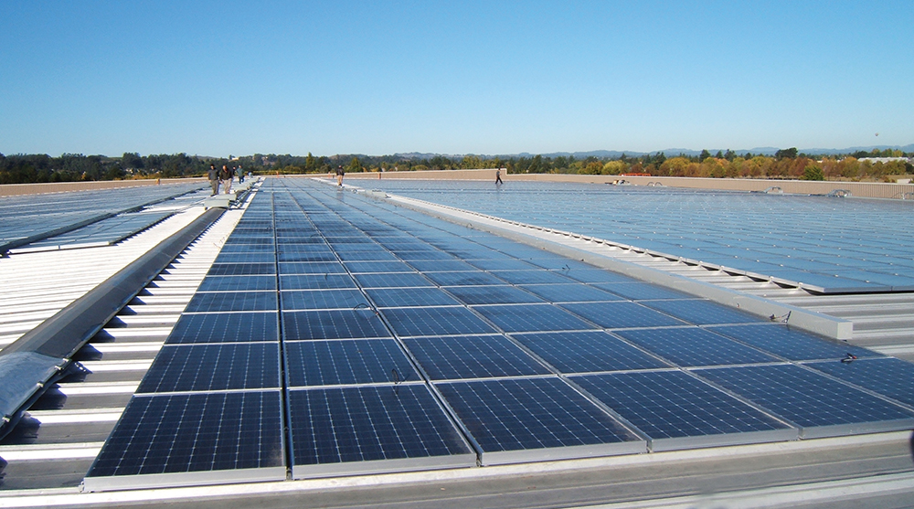
The First Inspection. The first system on Kate’s schedule for the week was a 1 MW system on the roof of a large commercial/industrial building (photo 1). The building was being converted from a manufacturing facility to a “green” multiunit apartment/condo building, but there was no construction ongoing at the time that the PV system was being installed and inspected. There was no internal access to the roof, and the building was 40 feet high. The installer had rented a scissor-jack man lift/equipment lift to get equipment and personnel to the roof for the installation, and this was used during the inspection process. The roof was flat, had a two-foot parapet, and the PV arrays were located some ten feet from the parapet, so safety harnesses were not required. The inverters for the system were located at ground level as was the main service panel where the utility interconnection was made.
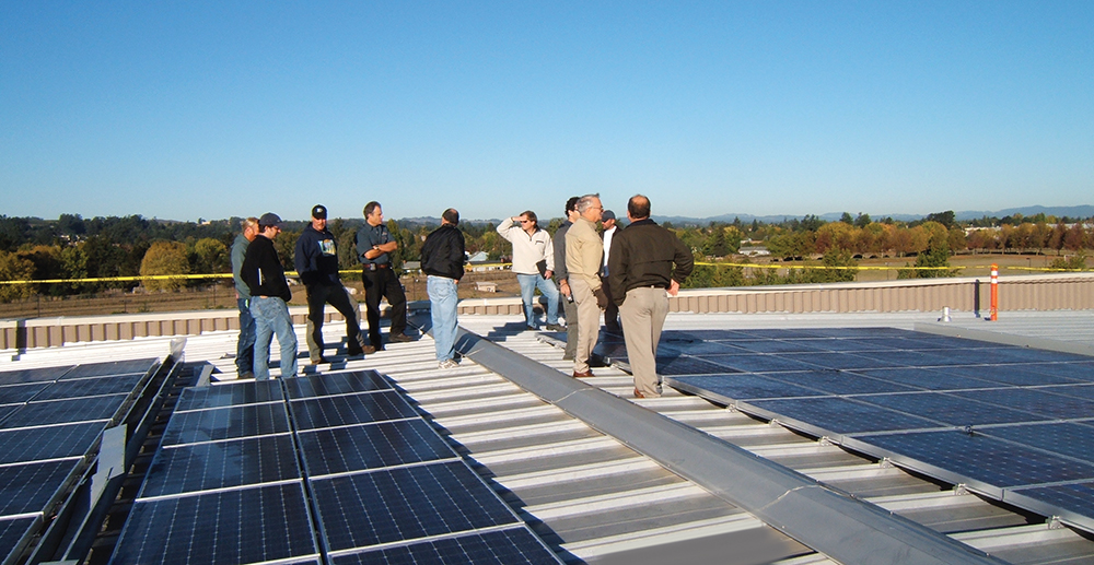
A system of this size was relatively new to the jurisdiction, and it was decided that on-the-job training was going to be conducted for all the electrical inspectors in the jurisdiction. A few inspectors were invited from a neighboring jurisdiction to be involved in the inspection process, which Kate would lead (photo 2). The utility had been notified and would have personnel and equipment on-site at the appropriate time to make the final interconnection.
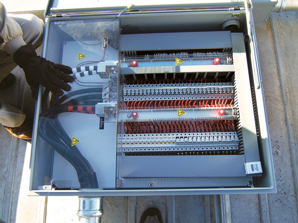
The system had numerous multiple strings of modules connected to combiners. The combiners were on the roof and had numerous fuses in finger-safe fuse holders (photo 3). At the time this system was permitted the jurisdiction had just adopted the 2014 NEC and had not yet implemented rapid shutdown requirements in 690.12, so the combiner boxes did not have any type of internal contactors that could be used to implement the rapid shutdown requirements.
Since the plan review had been very detailed and Ron the plan reviewer had okayed the basic design and list of materials, Kate was primarily interested in looking at the quality of the installation and whether or not the materials on the plan agreed with the materials that were installed and were properly installed. Based on the quality of the workmanship, she could see that this was a thoroughly professional installation. She knew this contractor from previous installations, and they always did an excellent job, but she still conducted her usual thorough inspection.
She looked closely at how the various racks of PV modules were connected to the building structure or roof and discussed this with the PV system installer who was accompanied by the system designer. She found that they had had a roofing company and structural engineering firm analyze the roofing membrane and roofing structure and that both organizations had approved (in writing) of the method used to attach the PV racking system to the roof.
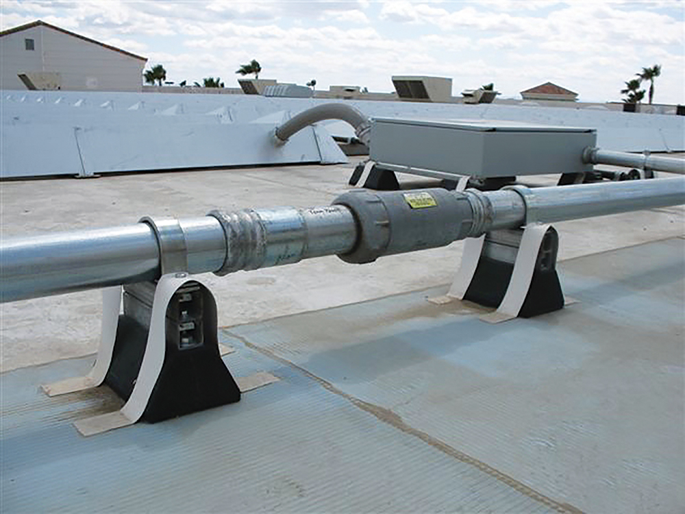
Kate also looked at the runs of EMT conduit on the roof and checked that the proper number and locations of expansion joints were used (photo 4). She also checked that the long runs of conduit had support structures which allowed the metal conduit to expand and contract as necessary as the temperatures varied. Her jurisdiction had come to an agreement with the various PV installers in the area that the expected low temperature used for voltage calculations would be -20° C (-4°F) and a high operational temperature on a parapet surrounded flat roof for conduits in the sun would be 70 to 80° C (158-176° F) depending on height of the conduit above the roof. Her jurisdiction was using the temperature adders in the 2014 NEC as were most of the PV installers in the surrounding jurisdictions and they were considering using these temperature adders, even after the 2017 NEC was adopted. The installers and the designers knew how hot sunlight exposed conduits could get. These temperatures were also used to determine the expansion of the steel conduits.
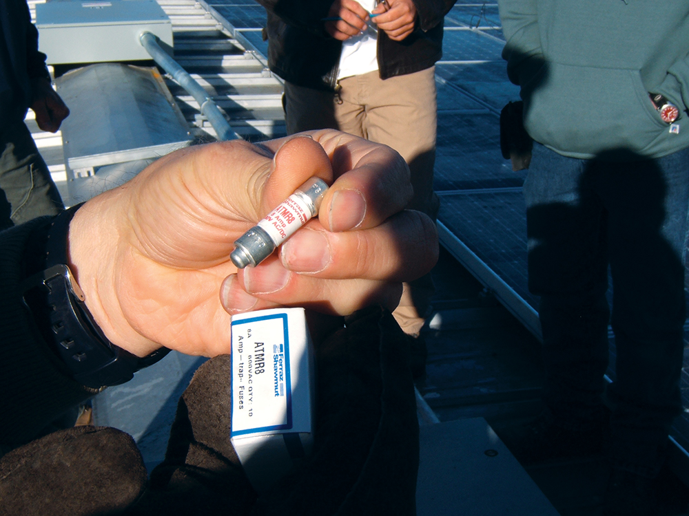
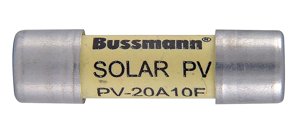
PV Fuses and Combiner Heating. When examining the dc string combiners on the roof, she found two of the numerous combiners had standard ATM-R8 dc rated Class R fuses installed and not the required fuses listed for PV [690.9(D)] (see photo 5). The installer made a quick trip the PV installation truck and had the correct PV fuses installed within an hour (photo 6).
Although ambient temperatures were moderate at this installation near the coast, Kate questioned the internal temperatures of the dc PV combiners which were in gray enclosures mounted in direct sun on the roof. The systems designer had internal temperature data that showed under the local conditions that the enclosures stayed below their listed temperature of 50°C. Kate noticed that the test data assumed a low-speed wind across the enclosures which helped to keep the temperatures within limits. When she pointed this out, the PV systems designer agreed that under no-wind conditions, the internal temperatures might be excessive causing nuisance operation of the fuses or premature failures. The PV systems designer suggested that the PV dc combiners be painted white; if that proved insufficient, sun shades would be installed over each combiner. Kate agreed and said that she wanted to see new test data with the white-painted combiners when it became available.
On the Ground. Back at ground level, inspecting the five inverters associated with this system went smoothly. Although listed equipment is normally not inspected internally by the AHJ, Kate made it a habit of at least checking the input and output connections and the observable wiring in the inverter to make sure that it complied with minimum requirements in the Code and any UL standard that she was familiar with. Kate noticed that her earlier observation that these inverters, although listed by Underwriters Laboratories (UL) as complying with UL Standard 1741, had been manufactured with flexible, fine-stranded cables between the ac output terminal block and the internal power electronics. She had also noted that those ac output terminal blocks were not listed for use with fine stranded conductors (110.14). Her earlier observations had resulted in a quick visit from the manufacturer of the inverter and the installers to the site to put proper terminations for the fine stranded conductors in the inverter so that they could be used with the existing power distribution blocks. In addition to electronic copies of the manuals for the equipment for this system that she carried in her notebook computer, she also had an electronic copy of the National Electrical Code (NEC), the National Electrical Code Handbook (NECH), and the UL White Book. The latter provides information on how specific categories of listed equipment should be utilized to comply with the safety standards.
The Interconnection Equipment. This megawatt PV system required a supply-side connection. The PV installation company had worked with the local UL 508 shop who had manufactured and installed the original 4000-amp premises switchgear to make the correct connections to the busbars between the meter section and the main distribution circuits (photo 7). On electrical systems of this size, the utility frequently installs potential transformers (PT) and current transformers (CT) that connect to the metering section.
These transducers were originally installed on the load side of the main disconnect for the facility. A connection in this location allows these transformers to be serviced safely in an unenergized state when the main disconnect is open.

Voltage and current measurement transformers connected in this location would have prevented the measurement of the net output power of the PV system since it was connected ahead of the main disconnect and its output would not be sensed. The utility, the UL 508 shop, and the PV installer worked together to move the CTs and PTs into the metering section ahead of the main disconnect and ahead of the PV supply-side interconnection point. The CTs and PTs were given their own set of metering disconnect switches so that they could be serviced safely.
The System Becomes Operational. After the interconnection to the utility was made, the PV installer closed the main ac PV system disconnect, and the system operation was observed and tested. The anti-islanding tests were conducted as described above. One inverter came back into service almost immediately when the main disconnect was closed instead of remaining idle (no power production) for the required five-minute delay. This was a software adjustment that had been improperly set at the factory, probably during the end of production testing, and was easily rectified using the factory provided password.
None of the arc-fault or ground-fault detectors indicated any problems. The PV system designer and installer verified that the ac power output was consistent with the sunlight intensity and module temperatures as measured by the data acquisition system.
The utility was satisfied that the system was safe from their point of view. Kate had skillfully conducted successful on-the-job training for not only the inspectors from her jurisdiction, but also for a few inspectors from nearby jurisdictions. This inspection and training with many questions and answers took all day. As the sun set, everyone went home informed and satisfied that a very good inspection had been conducted.
Summary
The events and people depicted above are fictionalized. However, PV systems, small and large, residential, commercial, and utility-scale are becoming more complex every year and with every Code cycle. Not only is the Fire Service pushing for enhanced safety through the PV rapid shut down system requirements, the utilities are imposing additional requirements on the inverter operation and interconnection systems. On-the-job training and continuing education of plan reviewers and inspectors are absolutely essential to having qualified, competent, professional people that are fully capable of discharging the responsibilities of ensuring the safety of the public.
The Southwest Technology Development Institute web site maintains a PV Systems Inspector/Installer Checklist and all copies of the previous “Perspectives on PV” articles for easy downloading. A color copy of the latest version (1.93) of the 150-page, Photovoltaic Power Systems, and the 2005 National Electrical Code: Suggested Practices, written by the author, may be downloaded from this web site: https://swtdi.nmsu.edu/codes-standards/