Numerous Code requirements apply to the PV array and other equipment located in the vicinity of the array. These include conductors, DC combiners, arc-fault protection equipment, and rapid shut down equipment. This article addresses some of these requirements as they are found in the 2020 National Electrical Code (NEC).
The Basics
Cable types. The conductors permanently attached to the PV module will typically be marked “PV Cable” or “PV Wire.” This is a special cable unique to the PV industry, which is mentioned only in Article 690 and nowhere else in the Code. This conductor is typically a 90°C, wet-rated conductor that is used in exposed locations. It has black insulation, is UV resistant and has a specified degree of mechanical strength.
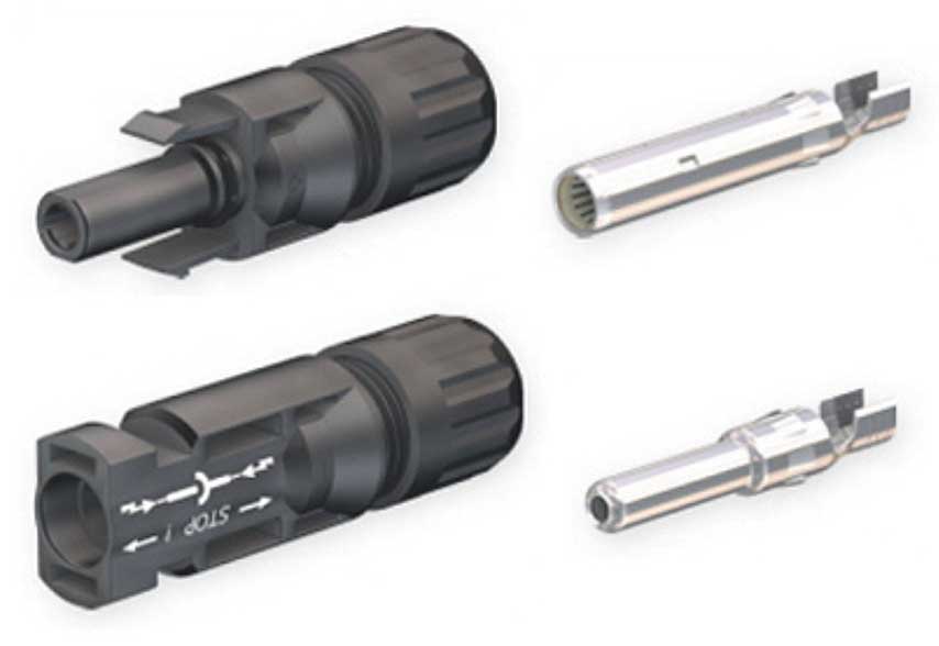
At the end of a series-connected string of modules or a series-connected string of dc-to-dc converters, the module wiring will generally have to be extended to reach a transition point to enter the building or to a dc combiner. The easiest way to extend these cables is to purchase extension cables with connectors attached from the distributor who is supplying the modules. However, care must be taken in matching the connectors attached to the module cables to the connectors attached to the extension cables [690.33(C)]. See the “Connector Conundrum” in the “Perspectives on PV” article in the March/April 2020 issue of the IAEI Magazine for the details.
This extension cable, when used in outdoor locations, may be either single conductor PV Cable/PV Wire or a single conductor type USE-2. If the extension cable is routed inside a raceway, then it should have the RHW-2 or XHHW-2 markings to indicate that it is a 90°C, wet-rated conductor that has been evaluated for use in raceways.
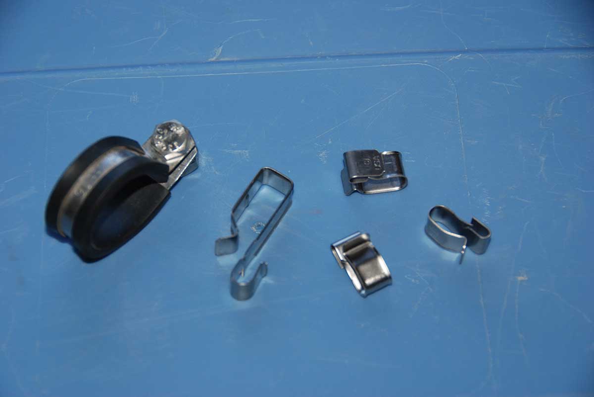
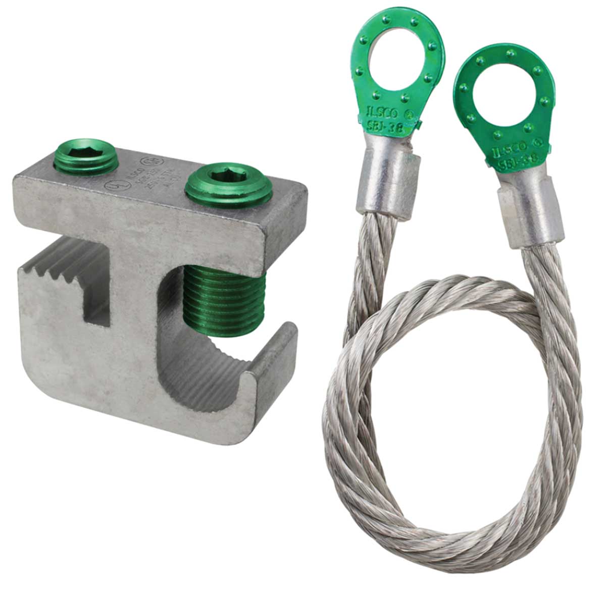
Exposed, single-conductor cables in a PV array are subject to quite severe mechanical stresses including high winds, snow, and ice, and birds and animals These single-conductor cables must be supported at intervals not to exceed 600 mm (24 in.) by an appropriate method [690.31(C)(1)]. Although black plastic cable ties (zip ties) are readily available and frequently used, many of these plastic cable ties have not withstood the test of time even when marked Sunlight Resistant. While some plastic cable ties may be durable in the PV environment, it is recommended that metallic cable attachment devices (clips) be used, which are readily available from the PV distributors (see photo 1).
When there are more than three single-conductor cables bundled together in close proximity (acts like a cable), additional mutual heating may be involved. In this case, NEC Table 310.16 (ah ha-back to the old numbering system for the 2020 NEC edition) and Table 310.15(C)(1) instead of Table 310.17 should be used for ampacity determinations [310.15(C)(1)].
AC PV modules and dc modules coupled to microinverters will have a multiconductor “trunk” cable attached to the ac output of each of the microinverters. Typically, this cable is daisy-chained from microinverter to microinverter and will eventually transition to a cable that can be run to an ac combiner box that is used where there are multiple “strings” of microinverters involved. Generally, the trunk cable is a type TC-ER cable, and it must be secured according to the instructions provided with the listed cable or at a minimum of every 1.8 m (6 ft) and within 600 mm (24 in.) of each connector or termination [690.31(C)(3)].
Combiners When there are more than two strings of modules to be connected in parallel, overcurrent protection devices (OCPD) are normally required for each string. This protects the string when faults occur in the string from currents, either originating in two or more other strings or in back feed from the interactive utility inverter. These overcurrent devices are typically located in a dc combiner which has the fuses installed in finger-safe fuse holders in a weatherproof enclosure (photo 2). The combiner may also have internal relays or contactors that are part of the rapid shut down system.

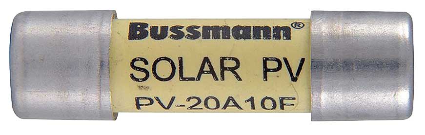
The dc combiner should be mounted in a location not in direct sunlight because internal heating due to solar radiation may cause the internal temperature of the combiner to exceed the listed operating temperature range of the fuses (normally 50°C), which could result in premature fuse opening or failure. Fuses in these combiners must be listed and identified as PV fuses since they have slightly different characteristics than the normal electronic fuses of the same size and rating (see photo 3).
Arc-Fault Circuit Protection (690.11). This section requires an arc-fault detector and circuit interrupter in the dc system where any circuit operates at 80 V dc or greater between two circuit conductors. This listed device(s) is required to detect and interrupt a series circuit in which an arc has formed, which could include arcs within the PV module, connectors, and other components in the dc circuits including conductors.
On smaller PV systems, the arc-fault detector/interrupter may be included in the inverter. With larger systems, the devices may be located both in the inverter and in combiner boxes within the array. PV arrays using AC PV modules or microinverters generally are not required to have arc-fault circuit protection, since the dc voltages in these systems are less than 80 V.
Rapid Shutdown of PV Systems on Buildings (690.12). To provide shock protection for firefighters and other first responders on buildings where PV systems are installed, a rapid shut down system is required. This rapid shut down system (RSS), when initiated, will reduce voltages within the PV array to no greater than 80 V within 30 seconds and DC conductors outside the array boundary to no more than 30 V within 30 seconds.
The RSS may include components at or in the utility-interactive inverter, at each module, and at or in any DC combiner. The simplest, most easily understood systems are where the PV system uses AC PV modules or PV modules with microinverters. The marked RSS initiation device is usually an ac PV disconnect or the main service disconnect. When ac power is removed from these PV array components, the requirements for rapid shut down have been met. However, as a minimum, the various microinverters associated with these systems must be listed and marked as rapid shut down equipment (RSE).
A more complex system has dc-to-dc converters attached to each module that communicate with a string inverter which controls the individual dc-to-dc converters with an initiation device in the inverter or nearby. In many cases removing ac power from the inverter will initiate the rapid shut down system. Both the inverter and the dc-to-dc converters must be listed and marked as rapid shut down equipment.
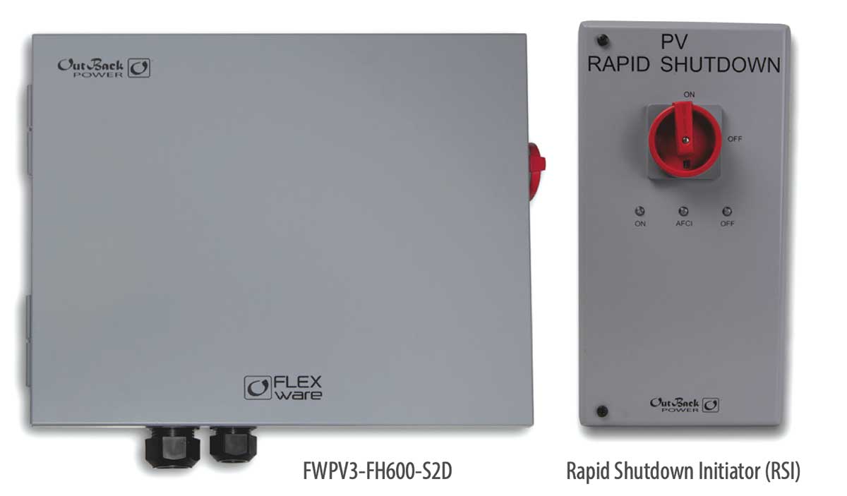
And on string inverter systems, there are several products that have devices that are installed at each PV module and these RSS devices are controlled by an initiator near the inverter or in a location required by the Code (photo 4).
Grounding and Bonding. PV modules with metallic frames (usually aluminum) shall be connected to an equipment grounding system sized in accordance with 690.43 and 690.45. That equipment grounding system may be an individual equipment grounding conductor connected to each module and daisy-chained between modules. Or, the modules may be bonded electrically with a listed bonding device to an Underwriter’s Laboratory listed UL 2703 racking system. Any connection between an aluminum surface such as a module frame or an aluminum rack and a copper conductor must address the dissimilar metals issue by using an approved device suitable for both metals. This is similar to the requirements for splicing a copper conductor to an aluminum conductor. The PV industry has developed a number of stainless-steel devices for this task (see photo 5). The module mounting/grounding “top clips” shown in photo 2 of the “Perspectives on PV” article in the March/April 2020 IAEI Magazine are being used more frequently with listed rack assemblies.
PV system grounding for utility-interactive PV systems being installed under the 2020 NEC will generally have the system grounding addressed by circuits in the inverter. These circuits, in many cases, are part of the dc ground-fault circuit interrupter system. And these PV systems are known as functionally grounded systems where the term “functionally” refers to at least one conductor of the system being connected or referenced to ground through the ground fault circuit interrupter. This conductor is not solidly grounded, and any ground-fault circuit interruption activity may completely remove any reference to ground of the circuit conductors.
Looking Deeper
Cables. If the outdoor-rated USE-2 or PV Wire/PV Cable extension cable conductors are to be routed through conduit or another raceway, they should also be marked RHW-2 or XHHW-2 to indicate that they have been evaluated for this use. However, the 2020 NEC says that PV Wire/PV Cable may be used in any location allowed for RHW-2 [690.32(C)(1)(2)]. This section is not clearly written since it appears to require that USE-2 and RHW-2 be marked Sunlight Resistant to be used in the exposed outdoor PV wiring. USE-2 is typically not marked Sunlight Resistant because it has only a 350-hour accelerated UV exposure test rather than the 720-hour test required to allow the Sunlight Resistant marking. That being said, USE-2 in PV applications has withstood the test of time, and installations more than 40 years old using USE-2 exposed conductors have shown no signs of cable deterioration.
PV Wire/PV Cable has several differing, nonstandard outer diameters and is not listed in the conductor properties or conduit fill tables in the Code, so the diameter must be measured or taken from the manufacturer’s data sheet and used with the restrictions shown in Table 1, Chapter 9.
Although the Code and UL Standard 4703 allow the use of PVC insulation on PV Wire/PV Cable, caution should be exercised when selecting cables with this insulation. I have not seen any PVC-insulated cables in actual PV installations, but UL Standard 4703 allows this construction. PVC-insulated cables and electrical raceways made of PVC and marked Sunlight Resistant have shown signs of severe deterioration after only 10-11 years in the sun-drenched, very hot PV outdoor environment. This may be due to the fact that the 720-hour accelerated UV test required to achieve the Sunlight Resistant marking represents only about two and a half years of outdoor, rooftop exposure in the sunny Southwest. In a similar manner, insulation colors other than black may not withstand the test of time because they lack the carbon black that gives black insulation its superior UV resistance.
Although not commonly done, splicing module cables to extension cables by soldering is still permitted by the NEC [110.14(B)] and could serve to meet these requirements where matching/mating connectors are not available [690.33(C)]. The electrical conductive properties and insulation properties of the spliced cable must be equal to or greater than those properties of the unspliced cable [110.14(B)]. That generally means mechanically strong splices, electrical grade solder, and heavy-duty heat shrink insulation. Of course, the labor time and convenience generally prohibit the use of this splicing technique.
Some connector manufacturers make connector kits that can be attached to bulk lengths of PV Wire/PV Cable in the field using the manufacturer’s specified assembly tools (photo 6). Unfortunately, many connectors are being installed on modules at the factory that have no corresponding field-installable connector kit.
Section 690.31 requires that all PV source and output circuits operating at voltages greater than 30 V and that are installed in readily accessible locations shall be guarded, of Type MC cable, or in a raceway. This would certainly apply to a ground-mounted PV array, and in many cases, a fence is installed around those arrays. Another option is to install a guard or barrier behind the modules such that the exposed conductors cannot be touched. This section also requires that dc PV circuits inside a building be enclosed in a metallic raceway or utilize Type MC cable from the point of first penetration of the building to the dc utilization equipment which is usually the utility-interactive inverter.
It has been noted that some trunk cables associated with ac PV modules or microinverters have had fine stranded conductors. These conductors have more strands than Class B or Class C stranding (Chapter 9, Table 10) and must be properly terminated with or in a device listed for use with such cables (110.14).
Combiners. Section 690.9(C) allows the use of a single overcurrent protective device to protect the ungrounded circuits In PV source and PV output circuits. Where a single overcurrent protective device is used in a PV source circuit, the PV output circuit and other source circuits must be protected by an overcurrent device in the conductor of the same polarity. This is now allowed due to enhanced ground fault detection methods. This is in opposition to previous code additions, which required an overcurrent protective device in both of these ungrounded circuit conductors.
Looking to the future, changes proposed for UL Standard 1741 for inverters may indicate that inverters are a source of backfeed currents under ground-fault conditions, which may necessitate overcurrent devices in both polarity conductors.
DC combiners mounted in direct sunlight, particularly if colored gray, may be subject to overheating from solar radiation and could cause unwanted overcurrent device activation. These combiners should be mounted in shaded areas, have a sunshade installed, or possibly be white in color. In some cases, fuse manufacturer’s data is available to allow the rating of the fuses to be corrected for high temperatures, but these data should be used with caution, since the fuse at normal temperatures may have a rating too high to protect the conductor. When the internal combiner temperatures exceed 50°C, the fuses are operating out of their listing range [110.3(B)].
Arc-fault Circuit Protection. PV systems that are not installed on or in buildings and that have conductors installed in metal raceways or underground are not required to have arc-fault circuit protection. These arc-fault detection/interruption devices, whether inside the inverter, inside the combiner box, or as separate units, should be listed and the presence of the device marked on the equipment. This NEC requirement has existed since the 2014 NEC and the UL Standard UL 1699B has been available since August 2018. There will be either a self-test or a manual test function associated with this device
Rapid Shutdown of PV Systems on Buildings. An initiation device will be used to control the rapid shutdown function of the PV system [690.12(C)]. That initiation device may be the service disconnecting means, the PV system disconnecting means, or a readily accessible switch that plainly indicates whether it is in the “off” or “on” position where “off” indicates that the PV system conductors have reduced voltages. For one- and two-family dwellings, the initiation device must be located in a readily accessible location outside the building. For new construction, the 2020 NEC in Section 230.85 requires that for one- and two-family dwellings, an emergency AC disconnect on the service conductors be located on the outside of the building. Three options are listed to meet this requirement. If this emergency disconnect is also used for the RSS initiator, then two requirements have been met simultaneously. Any and all equipment used for the rapid shut down system with the exception of the initiating device must be listed for use in the rapid shut down systems.
Section 690.56(C) establishes the requirements for the marking and labeling on the building that has a rapid shut down system. This includes warning labels and diagrams showing the location of the array and the initiation switch. There may be cases where parts of the PV array are from an earlier installation with different rapid shut down requirements or no rapid shut down requirements at all. The diagrams must indicate these differing rapid shut down requirements on the different sections of the PV array.
Grounding and bonding. Section 690.47(B) allows the metallic array mounting structure to be used as a grounding electrode where it meets the requirements of 250.52. This section also allows additional grounding electrode conductors to be connected to the PV module frames or the array racking structure. These additional grounding electrode conductors are permitted to be connected directly to additional grounding electrodes in accordance with 250.52 and 250.54. This additional array grounding is recommended in high lightning areas.
Section 690.41(B) requires that PV system dc circuits that exceed 30 V or 8 A shall be provided with dc ground-fault protection to reduce fire hazards. This is not an anti-shock GFCI requirement. This ground-fault protection equipment is built into most utility interactive inverters, but if it is not included, a warning label will be provided, and since it is a Code requirement, a separate device must be installed.
Summary
As I write this article, and as I hope you read it, the following ages-old thought comes to mind: “The devil is in the details.” This certainly applies to the requirements for installing the modules and other components at the “front end” of the PV system. It is the attention to the installation and the inspection of all of these details that will help to ensure the safety and reliability of the PV system for many decades. And yes, those PV modules, whether they are correctly installed or not, will be producing electrical energy for many decades. The safety of the public is our responsibility.