Article 230 is in some ways the genesis of the electrical system, meaning that it is very often the starting point of the electrical installation for a facility. Therefore, this is where I would usually commence my inspection process. As a rule of thumb, if the service is installed in a good workmanlike manner, the rest of the installation would also look good. However, if the service is a mess, you can generally assume that you are in for a long inspection and several items to note on your inspection record. The service is the location where we have some very specific things that have to happen to insure a good reliable system for the rest of the installation. The scope of this article covers the service conductors and equipment for control and protection of services and their installation requirements.
If we do a little review, the first item to remember is the term service point. Generally, it will be very close to the location of the service; and for most residential installations which are fed underground, the service point is at the meter base (see photo 1). From the service point, we start what we call the “service” which may consist of underground or overheard conductors, and then we will actually reach what most refer to as the service, or the main disconnect. If you will look at the first page of Article 230, you will find one of those handy road maps for the NEC. This diagram is a quick reference as to where you will find the requirements for a service installation.
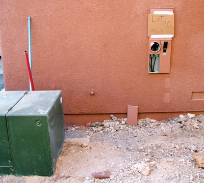
In 230.2 we find the limitation on the number of services for a building or structure; one service is usually all that is required. However, we may have special conditions which would qualify for an additional service. These are commonly at larger locations which will have fire pumps, emergency systems fed from generators, and now with the sudden rise in alternative energy, we may find other types of services (see photo 3). In 230.2(B), Special Occupancies, we have language which allows multiple services for larger facilities. Often on larger apartment complexes, you may find more than one service. This is commonly true if the serving utility supplies a single-phase service which can be limited in capacity. For example, we are limited to only 600 amps for this type of service by the utility in my area. We’ve even had large custom homes which had more than one service due to this limitation. This condition is covered in (C), and again you should be getting used to the fact that one set of rules doesn’t fit every condition, so we add the last sentence to (C) which is “by special permission.” This means that the AHJ can grant permission depending on justification which he sees fit to accept. An example of this would be some of the newer data centers being constructed where reliability is of the upmost importance, requiring redundancy within the system.
Continuing with 230.2 in (D), Different Characteristics, you will find that if you have the need for different voltages you may be allowed to have an additional service. This is common in a manufacturing facility where the office may be supplied for a 120/208-volt, 3-phase service; however, the plant has larger equipment which is more efficiently run on a 277/480-volt, 3-phase system. The last part of 230.2 is the Identification requirement, which states that if a location has more than one service or a combination of sources, then we will have to properly inform people of the other locations of power feeding that location. This is accomplished by the use of a permanent plaque or directory installed at each service notifying one of all the other service, feeders and branch circuits supplying the building or structure. As I mentioned in the last article, this is the same requirement as found in 225.37. This is more than just a convenience for the electrician, it is also for our first responders who in the event of an emergency need to disconnect all power sources to a facility and to do so in a fast, orderly fashion.
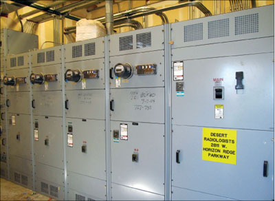
Photo 2. Here is an example of a large service with signage to identify the main. As a local amendment, Las Vegas codes require the main to have a yellow sign, which helps the first responders identify the mains service disconnects.
Briefly I will mention 230.3, which states that service conductors may not pass through the interior of another building. This leads us right into 230.6 which outlines what is considered to be outside of a building. Here you will find that if conductors are beneath a building under 2″ of concrete or buried 18″ down, or if you have a raceway totally encased in 2″ of concrete within a building, these conditions would be considered outside. In the 2011 edition of the NEC, we now have a new addition to this section, which is that a service riser conduit may pass through an eave when installed on the outside of a building. This is one of those areas I had never considered as inside a building for the short distance that the riser may pass through an eave; however, I guess technically it was.
The next two sections mention that no other conductors shall be contained within a raceway or cable with service conductors, with only two exceptions (which I will trust you to review, as these conditions don’t happen often). However, the requirement for raceway seals in 230.8 is one of the most overlooked and missed inspection items I’ve seen, even though it can have catastrophic results if not followed. Simply put, if you have raceways entering from underground you are to seal them, even spare empty conduits. There are several products on the market which are great for this, even duct seal putty or clay will do the job just fine. One of the reasons for this requirement is that if you have some condition which will cause overheating of the underground conductors and they are installed in PVC conduit, the conduit might exceed its allowable temperature and start to degrade and even off-gas. These gases could be and often are very flammable; so if there is any type of an ignition source, like a loose connection or an arc from a breaker actuation, it may cause these gasses to explode. This makes for great photos, however, it is very expensive to repair and the lost time for this type of failure is huge. The simple task of sealing these with an approved method limits this type of condition and could save thousands of dollars.
We will now cover several items which were mentioned briefly in my previous article. I stated in the last edition that there is a huge overlap between Articles 225 and 230 when it comes to clearances, so this will be a bit of review. However, don’t discount the importance of these requirements, as they are all related to safe installations. So open the code book and please review the actual language as I summarize these again. First in 230.9 and 230.10, we find that we need to keep conductors 3 ft. from any openings, which will include windows, doors, porches, balconies, ladders, stairs, fire escapes or similar locations.
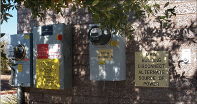
Photo 3. Here is an example of multiple services to one building, the normal power on the right and the alternate energy service on the left.
Overhead service conductors shall not be installed beneath any openings through which materials may be moved — which would include farm or other locations which may load and unload at an elevated portal — nor shall they block any building openings. And again vegetation shall not be used as a supporting means. Which brings to mind a situation, if you have a lodge pole pine tree that has died, is this still considered vegetation or is it now considered a utility pole? Where is the AHJ when you need him?
In Part II of 230 we get into specifics for overhead service conductors. First, these conductors are to be insulated, with one exception: the grounded conductor may not need to be insulated if it is part of a cable assembly. Next, we find the size and rating requirements. Generally, the conductors are to be sized to carry the calculated load as covered in Article 220; however, we do have a minimum size requirement in 230.23(B) which is 8 AWG copper or 6 AWG aluminum conductors. In 230.24 (A) and (B), we get into the specific clearances for overhead conductors which state they shall not be readily accessible, and it then expands further to explain what makes them meet this requirement. First, they shall have an 8-ft clearance over roofs, with five exceptions. Please read and review these on your own.
Next, we get the clearances from final grade. If the service voltage doesn’t exceed 150 volts to ground and the area is only accessible to pedestrians, then we only need a 10-ft clearance. This would commonly be a backyard. Next we cover residential property and driveways, and those commercial areas not subject to truck traffic, where the voltage doesn’t exceed 300 volts to ground. Here we need 12 feet of clearance, unless the voltage exceeds the 300-volt threshold, then the distance moves up to 15 feet.
Now for the last clearance: public streets, roads, and parking areas. Here we must have an 18-ft clearance. This is very important, as I’ve seen services pulled off walls by tall vehicles as a result of overhead conductors not meeting this requirement. This can obviously be a very dangerous condition. Also, please keep in mind that at certain times of the year we may have additional cable sag, which isn’t covered in the code specifically, but should be a design consideration.
One of the most important items to remember when in this area for those doing residential inspections is the additional clearance needed when dealing with swimming pools. This has to be mentioned here and you should take a moment to go to Article 680.8 and make sure you are aware of these distances, so that if you see a pool the little bell goes off in your head that you should double check all those clearance requirements specifically related to pools. Also note that in the 2011 NEC, we have new language to consider in 230.24(E) which mentions the clearance requirements from communication wires and cables.
Articles 230.26 through 230.28 deal with the attachment and support of overhead service conductors. The point of attachment shall never be lower than 10 feet, they shall be attached using fittings identified for the use with service conductors, and if the service mast is used as the support of the final span of the service conductors, it shall be of adequate strength. I mentioned in the last issue what I considered adequate. All this language boils down to this type of an installation, where the conductors are secured by a wedge clamp device that grips the bare grounded conductor which also has the steel core strand for strength, and then the conductors enter the raceway system through a weatherhead fitting.
Next we need to jump briefly to underground service conductors. These are generally utility-owned up to the meter, but you may have different local conditions. Underground service conductors are required to be insulated for the applied voltage, again with a few exceptions, which I will leave for you to review. The size and rating of these conductors don’t vary much from the overhead conditions. Where we have a different situation, in 230.32, Protection Against Damage, please note that the main reference here is to 300.5, where you will find a fair amount of installation requirements, do and don’ts, which we will cover when we reach that portion of the code. And the last item for underground service conductors is 230.33, which deals with splices. In rare cases, we may have to do splices, and this will refer you to the proper code requirements which may fit your application.
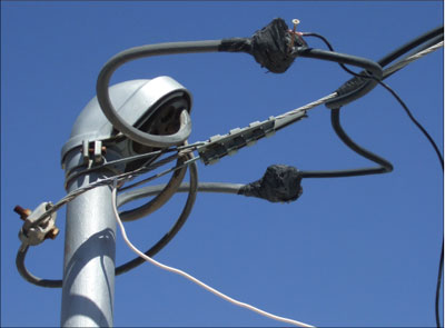
Photo 4. As an AHJ we are called out for all kinds of things. Here we had to investigate why a customer still had power even though he had no meter. However, getting past that issue, this photo is a good example of a weatherhead fitting for the proper conductor entrance to the raceway system, including a wedge clamp device which secures the conductors to the riser conduit.
We now move on to Section IV of Article 230, which is titled Service-Entrance Conductors, so this would appear to cover both the underground and the overhead applications. Section 230.40 states that each service drop, overhead service conductors, underground service conductors or service lateral shall only serve one set of service-entrance conductors. A little review here: remember the difference between overhead and underground service conductors and the overhead drop and the service lateral is dependent on who owns that portion of the system. The ironic part of 230.40 is that we follow it up with nearly half a page of exceptions to this simple one sentence requirement. One of these exceptions will allow multiple service-entrance conductors if we have multiple occupancies. From my experience, when you have a condition which isn’t simply a one-on-one situation, I would recommend reviewing this section of the code carefully to see which condition best matches what you are seeing in the field and work from there.
Moving on, I want to jump up to 230.44. I mention this only to introduce you to the fact that a cable tray installation is permitted for service-entrance conductors.
Let’s move on to more of the mechanics of service installations. In 230.54, we actually begin with the requirements for service heads where the conductors enter a raceway system. Here we cover some simple but very essential items related to how to make sure we have a good weatherproof installation and points of attachment, so we do everything possible to prevent moisture infiltration into our equipment (see photo 4). This would include a drip loop, which is one of the most basic items which I see being done poorly. The intent of a drip loop is to provide a path for water that comes in contact with the wire to drip off of a low point without directing the water into the raceway or into the connections.
So we have danced all around services, but the most basic item in a service we haven’t touched yet, and we finally get to it in Section V, Service Equipment – Disconnecting Means. Now comes the basic items that we typically train combination inspectors to concentrate on when doing service inspections, many of which are service change-outs or upgrades (see photos 5 and 6). The first item is that a means shall be provided to disconnect all conductors in a building or structure from the service-entrance conductors. In 230.70(A) we explore locations for these disconnects. The main rule is that they shall be in a readily accessible location, followed by an item stating that they shall not be in a bathroom. This leads to a little humor as bathrooms are a location I would not consider to be always readily accessible anyway. However, as we’ve said before, much of the code is written due to various interpretations which have caused the need for clarification. The next obvious but frequently missed item is that all service disconnecting means must be suitable for the prevailing conditions; this may require a certain rating of the equipment, or protection.
We continue into 230.71, where we are given the maximum number of disconnects for each set of service-entrance conductors. You will notice that I stated this in a particular way, as I’ve had enforcement issues before where we have tried to state that you are only allowed a maximum of six switches per building for disconnecting means; however, the code doesn’t exactly state that. If you have multiple sets of service-entrance conductors, you can have up to six for each set. Also we have a list of additional items which may be in your service equipment but are not included in this requirement, such as power monitoring equipment, surge-protective devices and a couple of other items.
Grouping of the Disconnects, 230.72, covers the requirement to have disconnects grouped. One of the most important items is that each disconnect shall be marked to indicate the load served: this is a must (see photo 2). The allowance for additional disconnects for such things as fire pumps, emergency systems and such are allowed above the six disconnect rule, but the code wants these separated from the others. The exact words are that these shall be “remote” from the others, so this is an AHJ call as to what is “remote.” One of the other issues that I’ve seen in multi-occupancy businesses is the fact that each occupant shall have access to the service disconnection means. This can be a real issue when the electrical rooms are often locked and the owners don’t like to give every tenant keys to the room. One reason for restricted access is to prevent tenants from storing stuff in the electrical room. Remember, we must maintain proper working clearances, and storage and electrical rooms don’t go together. One of the worst I discovered was a shopping center that decided they needed a security staff. Of course, they had to have an office to work out of, so they made the electrical room into a security office, complete with desks, chairs, microwave, lockers and more.
Electrical rooms that have service disconnects in them have to be maintained and have to allow easy access so that in the event of something getting out of hand, or the need arises to shut down a unit, it can be done without delay or creating a hazardous condition.

Photo 5 and 6. These photos show why we are writing these articles, because as combination inspectors we are running onto these types of code violation installations daily.
This leads to another issue we need to mention here; often these electrical rooms may be very large and the location of the multiple main disconnects may not always be obvious. It could even be on the backside of the equipment you see when you first enter the room. In these cases, we need to provide some form of information as to where each disconnect is. Remember, we could be dealing with first responders who are not familiar with all forms of electrical equipment, so proper signage and whatever else can be done to direct them to each main disconnect will be helpful.
Locally, one option was to paint yellow lines on the floor to guide firefighters to each switch location. We have to keep in mind that personnel may face conditions that are not optimal, such as impaired visibility due to smoke, so the markings on the floor may give us the most advantageous condition. Along with this thought, 230.77 states that it shall be plainly indicated if the switch is in the open (off) or closed (on) position.
Moving along, we have to review the rating of disconnects. Here we find some minimum sizes for certain types of services. First, it must be sized according to the load calculated back in Article 220. Now for some special conditions, if you have a one-circuit installation, then the minimum service shall not be smaller than 15 amps, as detailed in 230.79(A). In (B), a two-circuit service is limited to 30 amps. Moving up to a one-family dwelling in (C), the minimum is 100 amps, 3-wire. And then for the all others, there is a catchall in (D) where the smallest service shall be 60 amps.
Section VII, Service Equipment – Overcurrent Protection, starts with a very basic requirement: each ungrounded conductor shall have overcurrent protection. Further, the rating of this overcurrent device shall not exceed the rating of the conductor ampacity. However, no overcurrent device shall be installed in the grounded conductor, unless the breaker is one that simultaneously disconnects the grounded and the ungrounded conductors. The service overcurrent device shall be an integral part of the service disconnecting means or shall be located immediately adjacent thereto.
The last thing we need to review in this article is 230.95, Ground-Fault Protection of Equipment. There are a few conditions that have to be met to kick in this requirement. First, the service has to be rated 1000 amps or more, and be a solidly grounded wye service of more than 150 volts to ground but not exceeding 600 volts phase-to-phase. So what fits this? It would commonly be our 277/480 wye services. The grounded conductor shall be solidly connected to ground through a grounding electrode conductor. The other information related to this requirement covers the settings, fuses, and the performance testing requirement. Generally speaking, on the ground fault protected systems we had in our area, we required third party testing. This would insure that the devices were set at the proper settings according the installation and the design professional’s requirements. From the factory, the settings are generally set to minimums which will cause nuisance tripping if not adjusted properly. We would then get a copy of this report and submit it as part of the record for the job. This was the best way, due to the time and equipment required, for this type of testing to be conducted. One extra note here, as simple as this may sound it is always a good idea to have this done and the report in hand before you authorize it to be energized.
This concludes Article 230; once again we have only hit the high spots and provided information which is common in the field and for testing purposes. Please take the time to thoroughly review the article in detail for those areas not specifically covered here. In the next issue, we will cover Article 240, Overcurrent Protection.



Find Us on Socials